Network Monitoring Using
Cisco Service Assurance Agent
This chapter describes how to configure the Cisco Service Assurance Agent (SAA) to provide advanced network service monitoring information using Cisco IOS Software Release 12.2. This chapter contains the following sections:
• Understanding the Cisco SAA
• Cisco SAA Configuration Task List
• SAA Configuration Using the CLI Examples
• SAA Configuration Using SNMP Examples
For a complete description of the Cisco SAA configuration commands mentioned in this chapter, see the “Cisco Service Assurance Agent Commands” chapter of the Release 12.2 Cisco IOS Configuration Fundamentals Command Reference. To locate documentation of other commands that appear in this chapter, use the Cisco IOS Command Reference Master Index or search online.
To identify hardware or software image support for a specific feature, use Feature Navigator on Cisco.com to search for information about the feature or refer to the software release notes for a specific release. For more information, see the “Identifying Platform Support for Cisco IOS Software Features”
section in the “About Cisco IOS Software Documentation” chapter.
Understanding the Cisco SAA
The Cisco SAA is an application-aware synthetic operation agent that monitors network performance by measuring response time, network resource availability, application performance, jitter (interpacket delay variance), connect time, throughput, and packet loss. Performance can be measured between any Cisco device that supports this feature and any remote IP host (server), Cisco routing device, or mainframe host. Performance measurement statistics provided by this feature can be used for troubleshooting, for problem analysis, and for designing network topologies.
The Cisco SAA can be especially useful for enterprise and service provider networks, because it provides expanded measurement and management capabilities. In particular, the SAA is a reliable mechanism for accurately monitoring the metrics in service level agreements (SLAs).
Because SAA is accessible using Simple Network Management Protocol (SNMP), it also can be used in performance monitoring applications for Network Management Systems (NMSs) such as
CiscoWorks2000 (CiscoWorks Blue) and the Internetwork Performance Monitor (IPM). SAA
notifications also can be enabled via Systems Network Architecture (SNA) network management vector transport (NMVT) for applications such as NetView.
SNMP notifications based on the data gathered by the SAA allow the router to receive alerts when performance drops below a specified level and when problems are corrected. The SAA utilizes the Cisco Round Trip Time Monitor (RTTMON) MIB for interaction between external NMS applications and the SAA running on the Cisco devices. For a complete description of the object variables referenced by the SAA feature, refer to the text of the CISCO-RTTMON-MIB.my file, available from the Cisco MIB website.
New Features in Cisco IOS Release 12.2
Cisco IOS Release 12.2 includes new SAA capabilities that allow you to perform the following tasks: • Measure file transfer protocol (FTP) file download time using the FTP operation
• Monitor one-way latency reporting through enhancements to the Jitter operation
• Configure a new option for the Dynamic Host Configuration Protocol (DHCP) operation • Manually enable a responder port (using the rtr responder global configuration command) • Verify data for the udpEcho operation (using the verify-data RTR configuration command) • Configure new options for the rtr schedule global configuration ommand
• Restart an operation
Cisco IOS Release 12.2 adds the following enhancements to the RTTMON MIB: • Addition of rttMonAuthTable (allows the user to configure authentication strings) • Extensions of the rttMonJitterStatsTable and the rttMonLatestJitterOperTable • Addition of rttMonEchoAdminMode for FTP operation
• Extension of the rttMonAppl table (allows the user to enable the SAA responder using the MIB)
Cisco SAA Configuration Task List
To configure Cisco SAA, perform the tasks described in the following sections:. • Configuring SAA Operations (Required)
• Configuring the Operation Type (Required)
• Configuring SAA Operation Characteristics (Optional) • Scheduling the Operation (Required)
• Enabling the SAA Responder on Operational Targets (Required for certain operations) • Configuring SAA Control Message Authentication (Optional)
• Resetting the SAA (Optional)
• Restarting a Stopped Operation (Optional)
• Displaying SAA Status and SAA Operational Results (Required) • Changing the Memory Threshold for the SAA (Optional) • Configuring Specific Operations (Optional)
• Configuring SAA Operations Using SNMP (Optional) • Accessing SAA Data Using SNMP (Optional)
• Enabling SAA SNMP Notifications (Optional)
Examples of the Cisco IOS CLI configuration tasks are provided in the “SAA Configuration Using the CLI Examples” section. Examples of SNMP configuration tasks are provided in the “SAA Configuration Using SNMP Examples” section.
Note SAA is an expansion of the Response Time Reporter (RTR) feature introduced in Cisco IOS Release 11.2. SAA retains the use of the RTR acronym in many of the configuration commands, and for the configuration mode used to configure SAA operations. RTR is also used throughout the command line interface (CLI) in the output of help and show commands.
Configuring SAA Operations
Response time and availability information is collected by operations that you configure on the router. Operations use synthetic packets specifically placed in a network to collect data about the network. These packets simulate other forms of network traffic, as determined by the type of operation you configure. Operations usually consist of multiple probe packets sent into the network; operations in general can be thought of as collections of probes.
SAA operations are given specific identification numbers so you can track the various operations you configure and execute. SAA operations are configured in RTR configuration mode. To configure an SAA operation, use the rtr global configuration command. When using this command, you specify the identification number for the operation you are about to configure. The router prompt will change to
(config-rtr) to indicate that you are in RTR configuration mode.
To configure a new SAA operation, perform the following steps beginning in global configuration mode: Step 1 Enter RTR configuration mode using the rtr operation-number global configuration command. The
operation-number argument specifies an identification number for the operation you will be configuring. Step 2 Use one of the type commands listed in the “Configuring the Operation Type” section to specify which
type of operation you are configuring.
Step 3 (Optional) Configure characteristics for the operation, one characteristic per line, using the commands found in “Configuring SAA Operation Characteristics” section.
Step 4 Type exit to return to global configuration mode.
Step 5 (Optional) Set reaction conditions for the operation, as described in the “Setting Reaction Thresholds.” Step 6 Schedule the operation start time, as described in the “Scheduling the Operation” section.
For an example of this process, see the “IP/ICMP Path Echo Example” found in the “SAA Configuration Using the CLI Examples” section.
Configuring the Operation Type
You must configure the operation type before you can configure any of the other characteristics. Cisco SAA provides the types of operations:
Operation Type Function RTR Configuration Command1
IP/ICMP Echo The IP/Internet Control Message Protocol (ICMP) Echo operation measures end-to-end response time between a Cisco router and devices using IP. ICMP is a network-layer Internet protocol that reports errors and provides other information relevant to IP packet processing. Response time is computed by measuring the time taken between sending an ICMP echo request message to the destination and receiving an ICMP echo reply. Cisco SAA provides an option to compute response time on a specific path by using the Loose Source Routing option in IP packets. SAA also allows a user to measure quality of service (QoS) between endpoints by setting type of service (ToS) bits on an IP packet. The Loose Source Routing path that an IP/ICMP Echo operation should take can be set using the lsr-path RTR configuration command.
type echo protocol ipIcmpEcho
SNA Echo The Systems Network Architecture (SNA) Echo operation measures end-to-end response time between a Cisco router and devices using SNA. You can use the SNA system services control points Native Echo (SSCP-RU), or you can target SNA LU type 0 connections or SNA logical unit (LU) type 2 connections that use the Cisco NSPECHO host application.
type echo protocol snaRUEcho or
type echo protocol snaLU0EchoAppl or
type echo protocol snaLU2EchoAppl IP / ICMP
Path Echo
The Path Echo operations record statistics for each hop along the path that the operation takes to reach it destination. The IP/ICMP Path Echo probe computes this hop-by-hop response time between a Cisco router and any IP device on the network by discovering the path using traceroute. Typical usage of this type of operation is to isolate bottlenecks in a path.
Note Loose Source Routing (lsr) option is not available for this operation.
type pathEcho protocol IpIcmpEcho
TCP Connection The Transmission Control Protocol (TCP) Connection operation is used to discover the time taken to connect to the target device. This operation can be used to test virtual circuit availability or
application availability. If the target is a Cisco router, then SAA makes a TCP connection to any port number specified by the user. If the destination is a non-Cisco IP host, then the user must specify a known target port number (for example, 21 for FTP, 23 for Telnet, or 80 for HTTP server). This operation is useful in testing Telnet or HTTP connection times.
UDP Echo The User Datagram Protocol (UDP) Echo operation calculates UDP response times between a Cisco router and any IP-enabled device. Response time is computed by measuring the time taken to send a datagram and receive a response from the destination device (round-trip time). If the target is a Cisco router, then SAA sends a UDP datagram to any port number specified by the user. If the destination is a non-Cisco IP host, then the user must specify a known target port number.
type udpEcho
Jitter/UDP Plus The UDP Plus operation is a superset of the UDP Echo operation. In addition to measuring UDP round-trip time, the UDP Plus operation measures per-direction packet-loss, one-way delay time, and jitter. Jitter is the delay variance between received packets. Packet loss is a critical element in SLAs, and jitter statistics are useful for analyzing traffic in a voice over IP (VoIP) network. Packet loss is reported for how many packets are lost, and in which direction (source to destination or destination to source). Delay is also reported for each direction.
type jitter
HTTP The HTTP operation measures the Round Trip Time (RTT) taken to connect and access data from an HTTP server. The HTTP server response time measurements consist of three types:
• DNS lookup—RTT taken to perform domain name lookup. • TCP connect—RTT taken to perform a TCP connection to the
HTTP server.
• HTTP transaction time—RTT taken to send a request and get a response from the HTTP server (the probe retrieves the base HTML page only).
For a GET request, the SAA will format the request based on the URL specified. In application self-service mode, the application controlling this probe is responsible for specifying the content of the HTTP request. SAA HTTP RAW operations allow the use of the http-raw-request Cisco IOS configuration submode. The SAA will send the HTTP request, receive the reply, and report RTT statistics (including the size of the page returned).
type http operation get or
type http operation raw
FTP The FTP operation throughput probe measures the time taken to transfer (download) a file from a remote host to the Cisco router using FTP (over TCP). (To test only how long taken to connect to a FTP port (port 21), use the TCP Connection operation.)
type ftp
DHCP The SAA DHCP operation measures the round-trip time taken to discover a DHCP server and obtain an IP address lease from it. After obtaining an IP address, the SAA releases the IP address that was leased by the server.
The default DHCP operation sends discovery packets from every available IP interface. However, if a specific DHCP server address is configured for use on the system using the ip dhcp-serveripaddress global configuration command, then discovery packets will be sent only to that DHCP server.
type dhcp
Configuring SAA Operation Characteristics
To configure characteristics for SAA operations, perform the tasks described in the following sections: • Setting General Operational Characteristics
• Enabling Data Verification for Operations
• Setting Statistics Gathering Characteristics
• Setting History Characteristics
• Setting Reaction Thresholds
Setting General Operational Characteristics
To configure optional characteristics for Cisco SAA operations, use the following commands in RTR configuration mode:
DLSw+ Data-link switching plus (DLSw+) is the enhanced Cisco version of RFC 1795. The DLSw+ operation tunnels LAN traffic over IP backbones via TCP. Many enterprise customers use the DLSw+ technology to seamlessly connect LAN media over geographically disperse locations. The routers performing the tunneling of LAN traffic into TCP/IP are referred to as DLSw peers.
The SAA DLSw+ probe measures the DLSw+ protocol stack and network response time between DLSw peers. Normally DLSw peers communicate through TCP port 2065. A prerequisite to successfully running the SAA DLSw+ probe is to have a connected DLSw+ peer between the source and destination Cisco devices. On the source DLSw+ device, a probe can be defined for a DLSw+ partner peer that need not be running a Cisco image that contains SAA functionality.
type dlsw
DNS The Domain Name System (DNS) operation response time is computed by measuring the difference between the time taken to send DNS request and receive a reply. The operation queries for an IP address if the user specifies a host name or queries for a host name if the user specifies an IP address.
type dns
1. For complete command syntax, use the ? (help) feature of the CLI, or refer to the Cisco IOS Configuration Fundamentals Command Reference.
Operation Type Function RTR Configuration Command1
Command Purpose
Router(config-rtr)# frequency seconds Sets how often the operation should send a probe out to gather statistics. This command applies to all operation types.
Router(config-rtr)# lsr-path {name | ipaddr} [name | ipaddr]...
Defines a LSR path for an IP/ICMP echo probe. This command applies only to IP/ICMP Echo operations. Note LSR paths can be specified for IP/ICMP Echo
operations, but not for IP/ICMP PathEcho operations.
Enabling Data Verification for Operations
If you suspect that data corruption is occurring for operations, you can enable data verification. To verify data for a previously configured operation, use the following commands, starting in global configuration mode:
Router(config-rtr)# owner text Configures the SNMP owner of the operation. This command applies to all operation types.
Router(config-rtr)# request-data-size bytes Sets the protocol data size in the payload of the probe request packet of the probe. This command applies to the following operation types: IP/ICMP Echo, UDP Echo, Jitter, DLSW, and SNA Echo
Router(config-rtr)# response-data-size bytes Sets the protocol data size in the payload of the response packet of the operation. This command applies only to SNA Echo operations.
Router(config-rtr)# tag text Logically links operations in a group. This command applies to all operations.
Router(config-rtr)# timeout milliseconds Sets the amount of time the probe waits for a response from its request packet. This command applies to all operations.
Router(config-rtr)# tos number Defines the IP ToS byte for request packets.
This command applies to the following operation types: IP/ICMP Echo, UDP Echo, and Jitter.
Command Purpose
Command Purpose
Router(config)# rtr operation_id Specifies the operation number of the SAA operation you want to configure.
Router(config-rtr)# verify-data Enables data verification for IP/ICMP Echo, SNA Echo, UDP Echo, and Jitter operations. Checks each operation response for corruption. Use the verify-data command only when corruption may be an issue. Do not enable this feature during normal operation because it causes unnecessary overhead.
Router(config-rtr)# data-pattern hex-pattern Allows you to specify an alphanumeric character string to verify that a udpEcho operation payload is not getting corrupted. The default data pattern used by the SAA is ABCD. This command allows you to specify your own hexadecimal patterns to more precisely monitor different source-to-destination and destination-to-source packets. This command works only for UDP Echo operations in this release.
Setting Statistics Gathering Characteristics
SAA operations capture statistics and collect error information. By default, the following information is captured and collected:
• Minimum and maximum response times • Number of completions
• Sum of completion times
• Sum of the squares of completion times • Accumulation of errors for noncompletions • Total attempts (errors plus number of completions) • Statistical distributions of response times
A statistical distribution of response times can be thought of as a set of buckets that holds the results of a probe. Each bucket holds the completion count that falls into that specific time interval. To modify the time intervals use the statistics-distribution-interval RTR configuration command. To modify the number of buckets, use the distributions-of-statistics-kept command. For example, if the
statistics-distribution-interval command is set to 20 ms and the distributions-of-statistics-kept command is set to 3 (buckets a, b and c), and three RTT operations are performed with response times of 10 ms, 15 ms, and 30 ms, then the completion count for the buckets is 2 for a, 1 for b, and 0 for c. In most situations, you need not change the statistical distribution interval or size. Only change the size when distributions are needed (for example, when performing statistical modeling of your network). To control how much and which type of statistics are stored on the router, use the following commands in RTR configuration mode, as needed:
Command Purpose
Router(config-rtr)# distributions-of-statistics-kept size Sets the number of buckets or statistical distributions kept during the lifetime of the probe. Size is the number of buckets that contain data counts for their intervals. Applies to the following operations: IP/ICMP Echo, IP/ICMP Path Echo, UDP Echo, TcpConnect, DNS, DLSw, and SNA Echo.
Router(config-rtr)# hops-of-statistics-kept size Collects pathEcho statistical distributions per hop per path. Size specifies the number of hops for which statistics are collected per path for each probe Applies to IP/ICMP Path Echo operations only.
Router(config-rtr)# hours-of-statistics-kept hours Sets the number of hours for which statistics are maintained for the probe. Applies to the following operations: IP/ICMP Echo, IP/ICMP Path Echo, UDP Echo, TcpConnect, DNS, DLSw, and SNA Echo. For HTTP and Jitter operations, statistics are kept for the last 2 hours. This parameter cannot currently be reconfigured by a user.
Note When the distribution-of-statistics-kept command is set to the default (1), you need not set the statistics-distribution-interval command because it has no effect on the statistics kept. For more information, refer to the command documentation in the “Cisco Service Assurance Agent
Commands” chapter of the Cisco IOS Configuration Fundamentals Command Reference.
Setting History Characteristics
The SAA can collect data samples for a given operation; these samples are called history data. By default, history data is not collected. When history collection is enabled, SAA collects the last n data points. The number of data points are configured using the buckets-of-history-kept RTR configuration command.
When collecting history, SAA also introduces the concept of lives. A life is defined as the operational lifetime of a probe. When a probe is stopped and restarted, data is kept in new life entries (if the number of entries is two or fewer). If the number of entries is more than two, the oldest entry is overwritten by the new entry.
History is not supported for HTTP and Jitter operations.
Note Collecting history increases the RAM usage. Collect history only when you believe there is a problem in the network. For general network response time information, use the statistics collected by the SAA. See the “Setting Statistics Gathering Characteristics” section for more information on statistics collection.
Router(config-rtr)# paths-of-statistics-kept size Collects statistical distributions for multiple paths. Size specifies the number of paths for which statistical distribution buckets are maintained per hour for each probe. Applies to IP/ICMP Path Echo operations only.
Router(config-rtr)# statistics-distribution-interval milliseconds
Sets the time interval for each statistical distribution. Applies to the following operations: IP/ICMP Echo, IP/ICMP Path Echo, UDP Echo, TcpConnect, DNS, DLSw, and SNA Echo.
To control how much and which type of history is collected on the router, use the following commands in RTR configuration mode, as required:
To disable history collection, use the default value (0) for the lives-of-history-kept command rather than the filter-for-history none command. The lives-of-history-kept command disables history collection before the operation of the probe is attempted, and the filter-for-history command with the none keyword checks for history inclusion after the operation of the probe attempt is made.
Setting Reaction Thresholds
You can configure the operation to send threshold notifications and use those notifications to trigger additional collection of time delay statistics. You can also configure the operation to send notifications when the probe loses connection, reestablishes connections, times out, and first succeeds after a timeout. Thresholds can be a useful way to limit the amount of network notifications. For example, you could limit the sending of trap notifications to when a defined problem event occurs by setting a trap to be sent when a rising threshold is exceeded and another to be sent when the monitored connection recovers using the falling threshold specification.
Command Purpose
Router(config-rtr)# buckets-of-history-kept size For a pathEcho probe, sets the number of paths to store. For all other probes, sets the number (size) of data points to be kept. Applies to the following operations: IP/ICMP Echo, IP/ICMP Path Echo, UDP Echo, TcpConnect, DNS, DLSw, and SNA Echo.
Router(config-rtr)# filter-for-history {none | all |
overthreshold | failures}
Defines the type of information kept in the history table for the probe. This is a required command to enable history. The all, overthreshold, or failures keywords must be specified for history to work. Applies to the following operations: IP/ICMP Echo, IP/ICMP Path Echo, UDP Echo, TcpConnect, DNS, DLSw, and SNA Echo.
Router(config-rtr)# lives-of-history-kept lives Enables history collection and sets the number of lives maintained in the history table for the probe. Applies to the following operations: IP/ICMP Echo, IP/ICMP Path Echo, UDP Echo, TcpConnect, DNS, DLSw, and SNA Echo.
Router(config-rtr)# samples-of-history-kept samples For a pathEcho probe, sets the number of hops in a path. For all other probes, RTR sets the number of samples to 1. Applies to the following operations: IP/ICMP Echo, IP/ICMP Path Echo, UDP Echo, TcpConnect, DNS, DLSw, and SNA Echo.
To configure the rising threshold for an event, use the following command in RTR configuration mode when configuring the operation:
To configure the reaction conditions for an operation (including the falling threshold), use the following commands in global configuration mode:
Scheduling the Operation
After you have configured the operation, you must schedule the operation to begin capturing statistics and collecting error information. When scheduling an operation, it can start immediately or start at a certain month, day, and hour. Use the pending keyword when setting the operation to start at a later time. The pending keyword is also an internal state of the operation visible through SNMP. The pending state is also used when an operation is a reaction operation waiting to be triggered.
To schedule an SAA operation, use the following command in global configuration mode:
Note After you schedule the operation with the rtr schedule command, you cannot change the configuration of the operation with the rtr global configuration command. To change the configuration of a scheduled operation, use the no form of the rtr command. The no form of the command removes all the configuration information of the operation, including the schedule, reaction configuration, and reaction triggers. You can now create a new configuration for the operation.
If the operation is in a pending state (the default), you can define the conditions under which the operation makes the transition from pending to active with the rtr reaction-trigger global configuration command. When the operation is in an active state it immediately begins collecting information.
Command Purpose
Router(config-rtr)# threshold milliseconds Configures the rising threshold (hysteresis) that generates a reaction event and stores history
information for the operation. This command applies to all operation types.
Command Purpose
Step 1 Router(config)# rtr reaction-configuration operation-number [connection-loss-enable]
[timeout-enable] [threshold-falling milliseconds] [threshold-type option] [action-type option]
Configures certain actions (for example, checking for connection losses or timeouts) to occur based on events controlled by the SAA.
Step 2 Router(config)# rtr reaction-trigger operation-number target-number
Defines an action type that will activate the operation.
Command Purpose
Router(config)# rtr schedule operation-number
[life {forever | seconds}] [start-time
{hh:mm[:ss] [month day | day month] | pending | now |
after hh:mm:ss}] [ageoutseconds]
Schedules the operation by configuring the time parameters.
Enabling the SAA Responder on Operational Targets
The SAA Responder is a component embedded in the target Cisco routing device that allows the system to anticipate and respond to SAA request packets. The responder can listen on any user-defined port for UDP and TCP protocol messages. In a client/server terminology, the SAA Responder is a Concurrent
Multiservice Server.
A server listening on a user-specified port all the time on a router is prone to denial-of-service attacks. Therefore, the server should stop listening on that port after it services the request of the client. Because the ports on which to listen are unknown beforehand, there is a need for a mechanism through which the Responder can be notified on which port it should listen and respond. To meet this need, the SAA uses a Control Protocol to notify the Responder to listen on a particular port and protocol.
The Responder listens on a specific port for Control Protocol messages sent by an SAA. The control message carries information like the protocol, port number, duration, and so on. Upon receipt of the control message, the responder will enable the specified UDP or TCP port for the specified duration. During this time, the Responder accepts the requests and responds to them. The Responder disables the port once it responds to the SAA packet, or when the specified time expires. To further prevent security compromises, you can apply MD5 authentication for control messages.
The SAA Responder is needed only for the following nonnative services: TCP, UDP Echo, and Jitter (UDP +) operations. If services that are already provided by the target router (such as Telnet or HTTP) are chosen, the SAA Responder need not be enabled. For non-Cisco devices, the SA Responder cannot be configured and the SAA can send operational packets only to services native to those devices. To enable SAA Responder functionality on a router, use the following command in global configuration mode:
Configuring SAA Control Message Authentication
The SAA uses a control message protocol to communicate with the Cisco routers that are the target of SAA operations. For security reasons, users can enable authentication for the SAA Control Protocol. The authentication is provided using Message Digest 5 (MD5) authentication. This authentication requires key definition on the source and target SAA routers. Configure the key using the keychain global configuration command to enter key-chain configuration mode.
For details on how to configure key chains, refer to the “Managing Authentication Keys” section in the “Configuring IP Routing Protocol-Independent Features” chapter of the Cisco IOS IP Configuration Guide. See also the “SAA Control Protocol Authentication Example” section.
The rtr key-chain command notifies the SAA that it should use the previously configured key for authentication.
Command Purpose
Router(config)# rtr responder [type {udpEcho | tcpConnect} [ipaddr ipaddr] {port port}]
Enables SAA Responder functionality on a Cisco device. The optional type, ipaddr, and port keywords enable the SAA Responder to respond to probe packets without receiving control protocol packets. Note that if you use these keywords, however, generation of packet loss statistics will not be possible for the operation.
To configure the SAA RTR authentication, use the following command in global configuration mode:
Resetting the SAA
To perform an emergency reset of the SAA (including clearing all RTR configuration information), use the following command in global configuration mode:
Caution Use the rtr reset command only in extreme situations such as the incorrect configuration of a number of operations. The rtr reset command removes all SAA RTR configuration from the running configuration file.
In addition to stopping all operations and clearing the RTR configuration information, the rtr reset command returns the running configuration information to the startup condition. This command does not reread the configuration stored in NVRAM (the startup configuration file). To reconfigure the SAA, you must reenter the appropriate SAA configuration commands, or copy an existing configuration file containing your desired SAA configuration to the running configuration.
Restarting a Stopped Operation
To restart an operation, use the following command in RTR configuration mode:
Note that you can only restart operations in the active state; operations in the pending state cannot be restarted.
Displaying SAA Status and SAA Operational Results
To display information about the status and configuration of the SAA, use the following commands in EXEC mode, as needed. You can display information in a tabular or full format. Tabular format displays information in a column format that reduces the number of screens required to display the information. Full format displays all information using identifiers next to each displayed value.
Command Purpose
Router(config)# rtr key-chain name Specifies the key chain to be used for authentication of SAA operations.
Command Purpose
Router(config)# rtr reset Stops all operations and clears all SAA RTR configuration information.
Command Purpose
For examples of the information displayed by these commands, and explanations of the output fields, see the “Cisco Service Assurance Agent Commands” chapter of the Release 12.2 Cisco IOS Configuration Fundamentals Command Reference.
Changing the Memory Threshold for the SAA
To specify how much memory must be available on the router to allow SAA configuration, use the following command in global configuration mode:
The rtr low-memory RTR configuration command allows you to specify the amount of memory that must be available to allow SAA configuration. The default value is 25 percent of the memory available on the system at startup. If the amount of available free memory falls below the value specified in the rtr low-memory command, then the SAA will not allow new operations to be configured. (The low-memory value is also referred to as the lowWaterMark.) If the value is set to 0, then SAA operations can be created until the system runs out of memory.
The value of the rtr low-memory command should not exceed the amount of free memory available on the system. To determine the amount of free memory available on the system, use the show memory EXEC command.
Command Purpose
Router> show rtr application[tabular | full] Displays global information about the SAA feature. Router> show rtr authentication Displays authentication information.
Router> show rtr collection-statistics [number] [tabular | full]
Displays error totals collected for all operations or a specified operation.
Router> show rtr configuration [number] [tabular | full] Displays configuration values including all defaults for
all operations or a specified operation.
Router> show rtr distributions-statistics [number] [tabular | full]
Displays statistical distribution information (captured response times) for all operations or a specified operation.
Router> show rtr history [number] [tabular | full] Displays history collected for all operations or a
specified operation.
Router> show rtr operational-state [number] [tabular | full]
Displays the operational state of all operations or a specified operation.
Router> show rtr reaction-trigger [number] [tabular | full]
Displays the reaction trigger information for all operations or a specified operation.
Router> show rtr responder Displays SAA Responder information.
Router> show rtr totals-statistics [number] [tabular | full]
Displays the total statistic values (accumulation of error counts and completions) for all operations or a specified operation.
Command Purpose
Router(config)# rtr low-memory value Specifies the amount of memory (in bytes) that must be available to allow SAA configuration.
For example, if there is 6 MB of free memory when system starts up, and the default lowWaterMark is used, then SAA can use up to 4.5 MB memory for creating operations. If the free memory drops below 1.5 MB, then SAA cannot create any more operations.
Before every new operation is created, the SAA checks the lowWaterMark to ensure that it does not consume more memory than it is configured for.
The SAA also provides a MIB variable (rttMonApplProbeCapacity) to track how many operations (probes) can be created with the available memory. Each operation takes about 14 KB of memory (when default options are used). The equation to compute rttMonApplProbeCapacity is:
rttMonApplProbeCapacity =
MIN(((Free_Bytes_on_the_Router–rttMonApplFreeMemLowWaterMark) / Memory_required_by_each_probe),
(rttMonApplNumCtrlAdminEntry–Num_of_Probes_already_configured))
For example, when the system boots, the rttMonApplProbeCapacity variable might show that 200 operations can be configured. But if other subsystems in the router start using up more memory when network gets busy, the SAA may only be able to configure 150 probes.
The show rtr application EXEC command will display the number of operations that can be run on the device in the “System Max Number of Entries” field.
Configuring Specific Operations
The following sections provide more information on configuring the operations: • Configuring a Jitter Operation
• Configuring a DHCP Operation
Configuring a Jitter Operation
The primary function of Jitter (UDP+) operations is to measure response times for real-time traffic, such as VoIP.
When multiple packets are sent consecutively from source to destination, for example, 10 ms apart, and if the network is behaving ideally, the destination should be receiving them 10 ms apart. But if there are delays in the network (like queueing, arriving through alternate routes, and so on) the arrival delay between packets might be greater than or less than 10 ms. Using this example, a positive jitter value indicates that the packets arrived greater than 10 ms apart. If the packets arrive 12 ms apart, then positive jitter is 2 ms; if the packets arrive 8 ms apart, then negative jitter is 2 ms. For delay-sensitive networks like VoIP, positive jitter values are undesirable, and a jitter value of 0 is ideal.
In theory the delay incurred by packets traversing a route from host A to host B is equal in each direction. However, the delay in one direction may be much higher. There might also be asymmetric sending and receiving paths between host A and host B. The one-way delay statistics provided by the UDP+ operation addresses this need for per-direction information, and allows you to more readily identify where bottlenecks occur.
The Jitter operation was designed to measure the delay variance and packet loss in IP networks by generating synthetic UDP traffic. The Jitter operation sends n packets, each of size s, from source router to a target router (which should have SAA Responder enabled on it) each t ms apart. Each parameter is user-configurable. By default, ten packet-frames are generated every 10 ms with an RTP payload size of 10 bytes (Cisco gateways combine two such frames and send them every 20 ms) to simulate voice traffic.
The packets SAA sends out to measure Jitter carry packet sending sequence and receiving sequence information, and sending and receiving time stamps from source and responder. Based on these, Jitter operations are capable of measuring the following:
• Per-direction delay variance between packets (jitter) • One-way delay
• Per-direction packet-loss • Average round trip time
Jitter
Based on time stamps from consecutive packets, the sender can calculate the jitter value, which is the difference in the latency (interpacket delay). Note that for the interpacket delay the clocks on the two devices need not be synchronized.
One-Way Delay
The Jitter probe packet contains four time stamps for its journey from host A to host B and back again: time sent from A, time received at B, time sent from B, and time received at A. The one-way delay is computed using the following simple formulae:
one-way delay from A to B = time received at B–time sent from A one-way delay from B to A = time received at A–time sent from B
Therefore, to accurately measure per-direction delay between two devices, you must synchronize the clocks on each device. To synchronize the clocks on each device, you must configure the Cisco IOS Network Time Protocol (NTP) feature on both the source and destination devices.
If the sum of the source to destination (SD) and the destination to source (DS) values is not within 10 percent of the round-trip time, the one-way measurement value is considered faulty and is discarded. This type of inaccuracy usually is found in devices that are not time-synchronized.
To configure a Jitter operation, use the following commands beginning in global configuration mode:
Command Purpose
Step 1 Router(config)# rtr operation-number Specifies an operation and enters RTR configuration mode.
Step 2 Router(config-rtr)# type jitter dest-ipaddr {name |
ipaddr} dest-port port-number [source-ipaddr {name |
ipaddr}] [source-port port-number] [control {enable |
disable}] [num-packets number-packets] [interval inter-packet-interval]
Defines a Jitter operation.
Step 3 Router(config-rtr)# frequency seconds (Optional) Sets how often the operation should send a probe out to gather statistics.
Step 4 Router(config-rtr)# owner text (Optional) Configures the SNMP owner of the operation.
Step 5 Router(config-rtr)# tag text (Optional) Logically links operations in a group. Step 6 Router(config-rtr)# timeout milliseconds (Optional) Sets the amount of time the probe waits
You must also enable the SAA Responder on the destination device. To enable the Responder, configure the following global configuration command on the destination device:
Alternatively, you can enable the SAA Responder using SNMP with the rttMonApplResponder.0 -Integer 1 command from a network management application.
To monitor the operational state of the Jitter operation, use the show rtr operational-state EXEC command. To view the statistics gathered by Jitter operation, use the show rtr collection-statistics EXEC command.
Disabling SAA RTR Control Protocol for Jitter Operations
In some cases, you may wish to disable SAA RTR control protocol traffic while still allowing a Jitter operation. You can avoid control message traffic by configuring a specific port to be permanently open for the Responder.
Note If you disable the SAA RTR Control Procotol, only round-trip-time statistics will be gathered for the Jitter operation.
To disable RTR control protocol traffic, use the control disable option when configuring the Jitter operation on the origin device:
Then enable the SAA Responder on the destination device. With the control protocol disabled, you must specify the operation type, as shown here:
Step 7 Router(config-rtr)# tos number (Optional) Defines the IP ToS byte for request packets. (This command applies to the IP/ICMP Echo, UDP Echo, and Jitter operation types only.) Step 8 Router(config)# rtr schedule operation-number [life
seconds] [start-time {pending | now | hh:mm [monthday
| daymonth]}] [ageoutseconds]
Schedules the operation by configuring the time parameters.
Command Purpose
Command Purpose
Router(config)# rtr responder Enables SAA Responder functionality on a device.
Command Purpose
Router(config-rtr)# type jitter dest-ipaddr ipaddr dest-port port-number control disable
Configures the operation as a Jitter operation. • Use of the control disable keywords disable
RTR control protocol messages.
Command Purpose
Router(config)# rtr responder type udpEcho ipaddr ipaddr port
port-number Enables SAA Responder functionality on a device.
• Note that the udpEcho keyword corresponds to the Jitter operation type.
The following example shows the configuration for the sending device and the target device. The same port number is specified on each.
RouterA (Sending Device) Configuration
RouterA(config)# rtr 10
RouterA(config-rtr)# type jitter dest-ipaddr 172.24.132.100 dest-port 99 control disable
RouterB (Target Device) Configuration
RouterB(config)# rtr responder type udpEcho ipaddr 172.24.132.100 port 99
Note that in this configuration, most of the standard Jitter statistics can not be collected.
Configuring a DHCP Operation
To test how long is taken for the system to obtain an IP address from any DHCP server on the network, use the following commands beginning in global configuration mode:
To test how long is taken for the system to obtain an IP address from a specific DHCP server, use the following global configuration command in addition to the commands above:
Command Purpose
Step 1 Router(config)# rtr operation-number Specifies an operation and enters RTR configuration mode.
Step 2 Router(config-rtr)# type dhcp [source-ipaddr source-ipaddr] [dest-ipaddr dest-ipaddr] [option 82
[circuit-id circuit-id] [remote-id remote-id] [subnet-mask subnet-mask]]
Defines a DHCP operation. DHCP option 82 allows you to specify the circuit ID, remote ID, or the subnet mask for the destination DHCP server. Step 3 Router(config-rtr)# frequency seconds (Optional) Sets how often the operation should be
performed (for example, frequency 60 indicates once every 60 seconds).
Step 4 Router(config-rtr)# owner text (Optional) Configures the SNMP owner of the operation.
Step 5 Router(config-rtr)# tag text (Optional) Logically links operations in a group. Step 6 Router(config-rtr)# timeout milliseconds (Optional) Sets the amount of time the probe waits
for a response from its request packet. Step 7 Router(config)# rtr schedule operation-number [life
seconds] start-time {pending | now | hh:mm [monthday
| daymonth]} [ageoutseconds]
Schedules the operation by configuring the time parameters.
Command Purpose
Router(config)# ip dhcp-server ipaddress Specifies a single DHCP server to be used for DHCP requests from the system.
Configuring SAA Operations Using SNMP
SAA operations using SNMP can be created in two ways: through a createAndGo operation and through a createAndWait operation. Each operation has a specific set of variables that need to be defined before it can be operational. The following variables should be specified in the order shown:
• Set rttMonCtrlAdminStatus • Set rttMonCtrlAdminRttType • Set rttMonEchoAdminProtocol
• Set the rest of the configuration variables
Additionally, each operation requires specific variables to be set before it can be activated. The following is a comprehensive list of variables based on operation type:
• For Echo, pathEcho and DLSW operations:
– rttMonEchoAdminTargetAddress
• For udpEcho, tcpConnect and Jitter operations:
– rttMonEchoAdminTargetAddress – rttMonEchoAdminTargetPort • For HTTP operations: – rttMonEchoAdminURL • For DNS operations: – rttMonEchoAdminTargetAddressString – rttMonEchoAdminNameServer
Note DHCP operations do not require any additional variables.
For examples of configuring the SAA using SNMP, see the“SAA Configuration Using SNMP Examples”
section.
Modifying Configuration Parameters While an Operation Is Active
Operation configuration parameters (except for trigger admin variables) cannot be changed while the probe is running because the data storage gets affected by configuration changes. For example, if an operation is configured to poll every 60 seconds, then a statsCapture table will store 60 samples in an hour. But if the polling interval is changed while the operation is still running, the statsCapture data aggregation will become corrupted.
To change the configuration of an active operation using SNMP, perform the following steps: Step 1 Set rttMonCtrlOperState to immediateStop (3).
Step 2 Set rttMonCtrlAdminStatus to notInService (2). Step 3 Set required variables.
Accessing SAA Data Using SNMP
The results of SAA operations are stored in different tables of the CISCO-RTTMON-MIB.
Historical information is saved in the rttMonHistoryCollectionTable. Currently HTTP and Jitter operations do not support the rttMonHistoryCollectionTable.
The rttMonAppl table contains the general SAA information, such as number of operations supported on the device and the maximum capacity of the device.
For Echo, PathEcho, UDP Echo, TCP Connect, DLSw, DNS, FTP and DHCP operations: • Latest sample (updated after each frequency cycle) is stored in the rttMonCtrlOperTable.
• Statistical distribution information (aggregate of each sample, updated after each frequency cycle) is stored in the rttMonStatsCaptureTable and rttMonStatsTotalsTable.
• Error information (aggregate of each sample, updated after each frequency cycle) is stored in the rttMonStatsCollectTable.
For HTTP operations:
• Latest sample is stored in the rttMonLatestHTTPOperTable and the rttMonCtrlOperTable (only the rttMonLatestRttOperCompletionTime variable is updated).
• Statistical information is stored in the rttMonHTTPStatsTable and the rttMonStatsTotalsTable. For Jitter operations:
• Latest sample is stored in the rttMonLatestJitterOperTable and in the rttMonCtrlOperTable (only the rttMonLatestRttOperCompletionTime variable is updated).
• Statistical information is stored in the rttMonJitterStatsTable and the rttMonStatsTotalsTable. The following operations are not supported in the CISCO-RTTMON-MIB:
• HTTP first byte operations • Frame Relay operations • Path Jitter operations
• ATM interface service level monitoringoperations • Frame Relay service level monitoring operations
• Interface service level monitoring operations (Serial/hssi/dds/imaE1/imaT1) • Controller service level monitoring operations (Ds3/E3/T1/E1/ft1)
Enabling SAA SNMP Notifications
To enable SNMP notifications (traps or informs) to be sent from your system, use the following commands in global configuration mode:
The RTR notifications are defined in the CISCO-RTTMON-MIB (enterprise 1.3.6.1.4.1.9.9.42.2) and are as follows: • 1 rttMonConnectionChangeNotification • 2 rttMonTimeoutNotification • 3 rttMonThresholdNotification • 4 rttMonVerifyErrorNotification
For further SNMP configuration steps, see the “Configuring SNMP Support” chapter in this document.
SAA Configuration Using the CLI Examples
This section provides the following configuration examples for creating operations on a Cisco device using the Cisco IOS CLI:
• SNA Echo Example
• IP/ICMP Path Echo Example
• TcpConnect Example
• SAA Control Protocol Authentication Example
• Jitter Operation Example
• HTTP GET Operation Example
• HTTP RAW Operation Using RAW Submode Example
• HTTP RAW Operation Through a Proxy Server Example
• FTP Operation Example • DNS Operation Example
• DLSw Operation Example
• DHCP Operation Example
• Connection Loss Trigger Example
SNA Echo Example
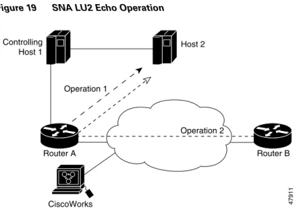
The example in Figure 19 shows probe 1 configured from Router A to Host 2, and probe 2 configured from Router B to Host 2. This configuration allows normative analysis of the network to determine a baseline from which triggers (and general reactions) are configured. Also, two SNA physical units (PUs)
Command Purpose
Step 1 Router(config)# snmp-server enable traps rtr Enables the sending of SAA RTR notifications. Step 2 Router(config)# snmp-server host host [traps | informs]
[version {1 | 2c | 3 [auth | noauth | priv]}]
community-string [rtr]
Specifies whether you want the SNMP
notifications sent as traps or informs, the version of SNMP to use, the security level of the notifications (for SNMPv3), and the recipient (host) of the notifications.
must be configured: CWBC0A and CWBC0B. For information on configuring SNA PUs, see the dspu host or the sna host command in the Cisco IOS Bridging and IBM Networking Command Reference, Volume 2.
Figure 19 SNA LU2 Echo Operation
Router A Configuration
RouterA(config)# rtr 1
RouterA(config-rtr)# type echo protocol snaLU2EchoAppl CWBC0A
RouterA(config-rtr)# exit
RouterA(config)# rtr schedule 1 start-time now
RouterA(config)#
Router B Configuration
RouterB(config)# rtr 2
RouterB(config-rtr)# type echo protocol snaLU2EchoAppl CWBC0B
RouterB(config-rtr)# exit
RouterB(config)# rtr schedule 1 start-time now
RouterB(config)#
Configuration Files for Router A and Router B
After you save the configurations for Router A and Router B (using the copy running-config startup-config EXECcommand), the following information is stored in the configuration files:
!Router A Configuration File ! Router A’s PU Configuration
sna host CWBC0A xid-snd 05dcc00a rmac 4001.3745.1088 rsap 4 lsap 12 focalpoint rtr 1
type echo protocol snaLU2EchoAppl CWBC0A paths-of-statistics-kept 1
hops-of-statistics-kept 1 samples-of-history-kept 1 rtr schedule 1 start-time now
!Router B Configuration File
!Router B’s PU Configuration from the Configuration File:
sna host CWBC0B xid-snd 05dcc00b rmac 4001.3745.1088 rsap 4 lsap 12 focalpoint rtr 2
type echo protocol snaLU2EchoAppl CWBC0B
47911 Router A Router B CiscoWorks Operation 1 Controlling Host 1 Host 2 Operation 2
paths-of-statistics-kept 1 hops-of-statistics-kept 1 samples-of-history-kept 1 rtr schedule 2 start-time now
IP/ICMP Path Echo Example
The example in Figure 20 shows that Operation 3 is configured on Router B to record statistics for each hop along the path that the operation takes to reach it destination (Router A).
Figure 20 IP/ICMP Path Echo Operation
This example sets up a pathEcho (with history) pending entry from Router B to Router A via IP/ICMP. It attempts to execute three times in 25 seconds (first attempt starts at 0 seconds) and keeps statistics for those three attempts in three history buckets. The entry can be started five times before wrapping over stored history (lives-of-history-kept = 5).
Router B Configuration
RouterB(config)# rtr 3
RouterB(config-rtr)# type pathEcho protocol ipIcmpEcho RouterA
RouterB(config-rtr)# frequency 10
RouterB(config-rtr)# lives-of-history-kept 5
RouterB(config-rtr)# buckets-of-history-kept 3
RouterB(config-rtr)# filter-for-history all
RouterB(config-rtr)# exit
RouterB(config)# rtr schedule 3 life 25
RouterB(config)# exit
Router B Configuration
After you save the configuration (using the copy running-config startup-config EXECcommand), the information is stored in the configuration file. Some necessary default forms of commands are
automatically included if they are not specified in the configuration setting, based on their necessity for operation execution. In this example, the default response-data-size command is added to the
configuration file automatically.
RouterB# show startup-config
47912 Router A Router B Controlling Host 1 Host 2 Operation 3 Performance management application
. . . ! rtr 3
type pathEcho protocol ipIcmpEcho 172.28.161.21 frequency 10
response-data-size 1 lives-of-history-kept 5 buckets-of-history-kept 3 filter-for-history all
rtr schedule 3 life 25 start-time pending !
. . .
Note that the SAA Responder need not be enabled on Router A for this operation.
TcpConnect Example
The example in Figure 21 shows a tcpConnect operation configured from Router B to the Telnet port (TCP port 23) of IP Host 1 (IP address 10.0.0.1).
Figure 21 TcpConnect Operation
Router B Configuration
RouterB(config)# rtr 5
RouterB(config-rtr)# type tcpConn dest-ipaddr 10.0.0.1 dest-port 23 control disable
RouterB(config-rtr)# exit
RouterB(config)# rtr schedule 5 start now
In the example, the Control Protocol for the probe is disabled. RTR Collector uses the RTR control protocol to notify the RTR Responder on the responder router to enable the target port temporarily. This action allows the Responder to respond to the probe packet. In this case, because the target is not a router and a well-known TCP port is used, there is no need to send the control message.
IP Host 1 Router A Router B 47913 TCP Connect operation Performance management
SAA Control Protocol Authentication Example
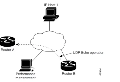
The example in Figure 22 shows a udpEcho probe configured from Router B to UDP port 888 on Router A (IP address 20.0.0.1).
Figure 22 udpEcho Operation
Note Configuring the SAA Control Protocol authentication is optional. However, if you configure authentication for Router B, you must configure the same authentication for Router A.
In the following configuration example, a key chain named csaa-key is configured on both routers. The rtr key-chain global configuration command enables RTR MD5 authentication on the control messages. Router A Configuration
RouterA(config)# key chain csaa-key
RouterA(config-keychain)# key 1
RouterA(config-keychain-key)# key-string secret
RouterA(config-keychain-key)# exit
RouterA(config-keychain)# exit
RouterA(config)# rtr key-chain csaa-key
RouterA(config)# rtr responder
Router B Configuration
RouterB(config)# key chain csaa-key
RouterB(config-keychain)# key 1
RouterB(config-keychain-key)# key-string secret
RouterB(config-keychain-key)# exit
RouterB(config-keychain)# exit
RouterB(config)# rtr key-chain csaa-key
RouterB(config)# rtr 6
RouterB(config-rtr)# type udpEcho dest-ipaddr 20.0.0.1 dest-port 888 control enable
RouterB(config-rtr)# exit
RouterB(config)# rtr schedule 6 start now IP Host 1
Router A
Router B 47914 UDP Echo operation
Performance management
Jitter Operation Example
In order to perform a Jitter operation (also known as a UDP+ operation), the SAA Responder must be enabled on the target router using the rtr responder global configuration command.
A Jitter operation consists of a train of packets sent at a constant interval. The numbers of packets sent and the interval are user-configurable. When the SAA Responder receives the packets, it time-stamps the reception time and then sends the packet back.
In the example shown in Figure 23, SAA operation number 200 is created and configured as a Jitter (UDP+) operation using the destination IP address 172.24.132.100, destination UDP port number 99. The operation will send 20 packets at 20-ms intervals.
Figure 23 Jitter Operation
Router A Configuration
RouterA(config)# rtr responder
Router B Configuration
RouterB(config)#rtr 200
RouterB(config-rtr)#type jitter dest-ip 172.24.132.100 dest-port 99 num-packets 20 interval 20
After the Jitter operation has run, you can display the results with the show rtr collection-statistics EXEC command. The following example shows sample output:
Entry Number: 200
Target Address: 172.24.132.100, Port Number: 31337 Start Time: *14:14:14.000 EST Thu Apr 6 2000 RTT Values:
NumOfRTT: 2800 RTTSum: 4792 RTTSum2: 8830 Packet Loss Values:
PacketLossSD: 0 PacketLossDS: 0
PacketOutOfSequence: 0 PacketMIA: 0 PacketLateArrival: 0 InternalError: 0 Busies: 0
Jitter Values:
MinOfPositivesSD: 1 MaxOfPositivesSD: 1
NumOfPositivesSD: 249 SumOfPositivesSD: 249 Sum2PositivesSD: 249 MinOfNegativesSD: 1 MaxOfNegativesSD: 2
NumOfNegativesSD: 238 SumOfNegativesSD: 239 Sum2NegativesSD: 241 MinOfPositivesDS: 1 MaxOfPositivesDS: 1 IP Host 1 Router A Router B 18172 Jitter operation CiscoWorks
NumOfPositivesDS: 97 SumOfPositivesDS: 97 Sum2PositivesDS: 97 MinOfNegativesDS: 1 MaxOfNegativesDS: 1
NumOfNegativesDS: 92 SumOfNegativesDS: 92 Sum2NegativesDS: 92
The values shown indicate the aggregated values for the current hour. RTT stands for Round-Trip-Time.
Table 25 describes the significant fields shown in the display.
The DS values show the same information as above for DS Jitter values.
HTTP GET Operation Example
In the example shown in Figure 24, operation 5 is created and configured as an HTTP GET operation. The destination URL is http://www.cisco.com:
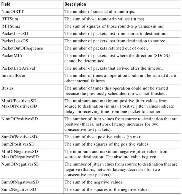
Table 25 show rtr collection-statistics Field Descriptions
Field Description
NumOfRTT The number of successful round trips. RTTSum The sum of those round-trip values (in ms).
RTTSum2 The sum of squares of those round-trip values (in ms). PacketLossSD The number of packets lost from source to destination. PacketLossDS The number of packets lost from destination to source. PacketOutOfSequence The number of packets returned out of order.
PacketMIA The number of packets lost where the direction (SD/DS) cannot be determined.
PacketLateArrival The number of packets that arrived after the timeout.
InternalError The number of times an operation could not be started due to other internal failures.
Busies The number of times this operation could not be started because the previously scheduled run was not finished. MinOfPositivesSD
MaxOfPositivesSD
The minimum and maximum positive jitter values from source to destination (in ms). Positive jitter values indicate delays in receiving time from one packet to another.
NumOfPositivesSD The number of jitter values from source to destination that are positive (that is, network latency increases for two
consecutive test packets).
SumOfPositivesSD The sum of those positive values (in ms). Sum2PositivesSD The sum of the squares of the positive values. MinOfNegativesSD
MaxOfNegativesSD
The minimum and maximum negative jitter values from source to destination. The absolute value is given.
NumOfNegativesSD The number of jitter values from source to destination that are negative (that is, network latency decreases for two
consecutive test packets). SumOfNegativesSD The sum of the negative values.
Figure 24 HTTP Operation
Router B Configuration
RouterB(config)#rtr 5
RouterB(config-rtr)#type http operation get url http://www.cisco.com
RouterB(config-rtr)# exit
RouterB(config)# rtr schedule 5 start-time now
HTTP RAW Operation Using RAW Submode Example
In the following example, SAA operation 6 is created and configured as an HTTP RAW operation. To use the raw commands, enter HTTP-RAW submode through use of the http-raw-request RTR configuration command. The RTR HTTP-RAW configuration submode is indicated by the
(config-rtr-http) router prompt. (config)# rtr 6
(config-rtr)# type http operation raw url http://www.cisco.com
(config-rtr)# http-raw-request
(config-rtr-http)# GET /index.html HTTP/1.0\r\n
(config-rtr-http)# \r\n
(config-rtr-http)# exit
(config)# rtr schedule 6 start-time now
HTTP RAW Operation Through a Proxy Server Example
In this example, http://www.proxy.cisco.com is the proxy server and http://www.yahoo.com is the HTTP server:
(config)# rtr 6
(config-rtr)# type http operation raw url http://www.proxy.cisco.com
(config-rtr)# http-raw-request
(config-rtr-http)# GET http://www.yahoo.com HTTP/1.0\r\n
(config-rtr-http)# \r\n
(config-rtr-http)# exit
(config)# rtr schedule 6 start-time now
HTTP server Router A Router B 18170 HTTP operation Performance management li ti
FTP Operation Example
An FTP operation is configured as shown in Figure 25.
Figure 25 FTP Operation
In this example, SAA operation 20 is configured as an FTP operation; ira is the user, smith is the password, zxq is the host name or address, and test is the file name.
RouterB(config)# rtr 20
RouterB(config-rtr)# type ftp operation get url ftp://ira:smith@zxq/test
RouterB(config-rtr)# exit
RouterB(config)# rtr schedule 20 start-time now
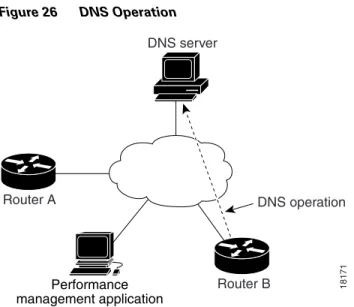
DNS Operation Example
In the example following Figure 26, SAA operation 7 is created and configured as a DNS operation using the name server IP address 172.20.2.132:
FTP server Router A Router B 38175 FTP operation Performance management
Figure 26 DNS Operation
RouterB(config)#rtr 7
RouterB(config-rtr)#type dns target-addr lethe name-server 172.20.2.132
RouterB(config-rtr)# exit
RouterB(config)# rtr schedule 7 start-time now
DLSw Operation Example
In the example following Figure 27, DLSw peers 172.20.26.10 and 172.21.27.11 are configured:
Figure 27 DLSw Operation
Router A Configuration File
RouterA# show running-config
. . . dlsw local-peer peer-id 172.20.26.10 dlsw remote-peer 0 tcp 172.21.27.11 . . . rtr 1 type dlsw peer-ipaddr 172.21.27.11 rtr schedule 1 start-time now . . . DNS server Router A Router B 18171 DNS operation Performance management application Router A 172.20.26.10 Router B 172.21.27.11 18173 DLSw operation
Router B Configuration File
RouterB# show running-config
. . . dlsw local-peer peer-ip 172.21.27.11 dlsw remote-peer 0 tcp 172.20.26.10 . . .
DHCP Operation Example
In the following example, SAA operation number 4 is configured as a DHCP operation enabled for DHCP server 172.16.20.3. Note that DHCP option 82 is used to specify the circuit ID.
Router(config)# rtr 4
Router(config-rtr)# type dhcp option 82 circuit-id 10005A6F1234
Router(config-rtr)# exit
Router(config)# ip dhcp-server 172.16.20.3
Option 82 is is called the Relay Agent Information option and is inserted by the DHCP relay agent when forwarding client-originated DHCP packets to a DHCP server. Servers recognizing the Relay Agent Information option may use the information to implement IP address or other parameter assignment policies. The DHCP server echoes the option back verbatim to the relay agent in server-to-client replies, and the relay agent strips the option before forwarding the reply to the client.
The Relay Agent Information option is organized as a single DHCP option that contains one or more suboptions that convey information known by the relay agent. The initial suboptions are defined for a relay agent that is co-located in a public circuit access unit. These include a circuit-id for the incoming circuit, a remote-id that provides a trusted identifier for the remote high-speed modem, and the subnet-mask of the logical IP subnet from which the relay agent received the client DHCP packet.
Connection Loss Trigger Example
Figure 28 shows SAA operations 1, 2, and 3 in the network. This example shows how to configure a trigger if operation 2 encounters a connection loss from Router B to Host 2. If a connection loss occurs between Router B and Host 2, a trap is issued, an SNA network management vector transport (NMVT) alert is issued, and the operation 3 state is changed to active.