Disclosure to Promote the Right To Information
Whereas the Parliament of India has set out to provide a practical regime of right to
information for citizens to secure access to information under the control of public authorities,
in order to promote transparency and accountability in the working of every public authority,
and whereas the attached publication of the Bureau of Indian Standards is of particular interest
to the public, particularly disadvantaged communities and those engaged in the pursuit of
education and knowledge, the attached public safety standard is made available to promote the
timely dissemination of this information in an accurate manner to the public.
इंटरनेट
मानक
“
!ान $ एक न' भारत का +नम-ण
”
Satyanarayan Gangaram Pitroda“Invent a New India Using Knowledge”
“
प0रा1 को छोड न' 5 तरफ
”
Jawaharlal Nehru“Step Out From the Old to the New”
“
जान1
का
अ+धकार
,
जी1
का
अ+धकार
”
Mazdoor Kisan Shakti Sangathan
“The Right to Information, The Right to Live”
“
!ान एक ऐसा खजाना > जो कभी च0राया नहB जा सकता ह
ै”
Bhartṛhari—Nītiśatakam“Knowledge is such a treasure which cannot be stolen”
“Invent a New India Using Knowledge”
ह
ै”
ह
”
ह
IS 2131 (1981): Method for standard penetration test for
soils [CED 43: Soil and Foundation Engineering]
Indian Standard
IS :2131 - 1981
(
R4fiied 1997 )METHOD FOR STANDARD
PENETRATION TEST FOR SOILS
( First Revision )
Third Reprint MARCH 1997
UDC
624.131.381
@ Copurigh’
1982
BUREAU
OF INDIAN
STANDARDS
MANAK BHAVAN. 9 BAHADUR SHAH ZAFAB MARG NBWDELHI 1lOOLZ
Gr
3
February1982
IS : 2131- 1981 ( Reaffmed 1997 )
Indian Standard
METHO~D FOR STANDARD
PENETRATION TEST FOR SOILS
( First Revision )
- Soil Engineering and Rock Mechanics Sectional Committee, BDC 23
Chairman Representing
DR JAODISH NARAIN University of Roorkee, Roorkee
ADDITIONAL DIRECTOR RESEARCH Ministry of Railways ( P. E. ) RDSO
DEP&Y DIRECTOR RESEARCH ( SOIL-MEOE ) RDSO ( Alternate )
SHRI P. D. AQARWAL Public Works Department, Government of Uttar
Pradesh, Lucknow
DR B. L. DHAWAN ( AItcrnatc )
DR ALAX SINQE University of Jodhpur, Jodhpur
COL AVTAR SIN~H Engine&-in-Chief’s Branch, Army Headquarters
LT-COL V. K. KANITXAR ( Abrnatc )
CHIEF ENQINEER ( D&R ) Irrigation Department, Government of Punjab, _ Chandigarh
DR G. S. DEILLON ( Alfern& ) SHRI M. C. DANDAVATE
SHRI N. %. DUQ~AL ( Alternate ) SERI A. G. DASTIDAR
DB G. S. DEILLON DIRECTOR, IRI SHRI A. H. DIVANJI
SHRI A. N. JANOLE (~Altcmztc)
DR GOPAL RAJAN DR GOPAL RANJAN
The Concrete Association of India, Bombay In personal capacity (5 Hungerford Street, 12/I,
Hungerford Court, Calcutta 700017 ) Indian Geotechnical Society, New Delhi
Irrigation Department, Government of Uttar Pradesh, Roorkee
AsiaB~~b~ations and Construction (P) Ltd,
SERI S. G~~PTA
Institution of Engineers ( India ), Calcutta University of Roorkee, Roorkee
Cemindia Co Ltd, Bombay
. \
SHRI N. V. DE SOUSA ( Alternate ]
SHRI G. S. JAIN
SHRI VIJAY K. JAIIU ( Alternate)
G. S. Jain & Associates, Roorkee
( Continued m gage 2 )
I
Q Copvright 1982
BUREAU OF INDIAN STANDARDS I
I
This publication is protected under the Indian Cojyrighr Ad (XXV of 1957 ) and reproduction in whole or in part by any means except with written permission of the publisher shall be deemed to be an infringement of copyright under the said Act. IIS : zl31- 1981
( Continued from page 1 )
Members Representing
SHRI A. B. JOSHI Central Water Commission, New Delhi DEPUTY I;IRECTOR ( CSMRS ) ( Alternate )
COL M. V. KsYERKAR Ministry of Defence ( R&D ) SHRI V. B. GRORPADE ( Altcraate )
SHRI 0. P. MALHOTRA Public Works Department, Chandigarh Adminis- SHRI D. R. NARAHARI
tration, Chandigarh
Central Building Reztearch Institute ( CSIR ), SHRI B. G. RAO ( Alternate )
SHRI T. K. NATRAJAN Da G. V. RAO
DR K. K. GUPTA ( Alternate ) RESEAROH OFFICER ( B&RRL ) SH~I K. R. SA~ENA
SECRETARY
Roorkee -
Central Road Research Institute, New Delhi Indian Institute of Technology, New Delhi
Public Works Department, Government of Punjab, Chandigarh
Engineering Research Laboratories, Government of Andhra Pradesh, Hyderabad
Central Board of Irritation & Power, New Delhi DEPUTY SECBETARY ( Alternate )
SEW N. SIVAQURU Roads Wing (Mmiatry of Shipping and Transport )
SHRI D. V. SIKKA ( Alternate)
SHBI K. S. SRINIVASAN National Buildings Organization, New Delhi Snnr SUNIL BERRY ( Altrrnats )
SEXIN. SUBRAMANYAM Karnataka Engineering Research Station, SWPER~NTENDINQ E N Q I N E E a ~riahnarajaiagar -
( P&D% ) Publ;Jorhz;rtment, Government of Tamil
EXECUTIVE ENGINEER ( SMRD ) ( Alter;: )
SHRIG. RAMAN, Director General, IS1 ( Ex-OS& Mmber ) Director ( Civ Engg )
secretary S-1 K. M. MATHUR Deputy Director ( Civ Engg ), BlS
The Site Exploration and Investigation for Foundation Subcommittee, BDC 23 : 2
Members
!3xn1V.S. AWARWAL Centr$or~elding Research Institute ( CSIR ), SHRI M. P. JA~N ( Altematr )
DR ALAM SINQH University of Jodhpur, Jodhpur
DEPUTY DIREOTO~ RES~A~OR Minirtry of Railways (PE), RDSO
ASEXSTANT DIRECTOR RESEAXOH ( SOIL MEOH ) RDSO ( Alternate )
DIBEOTOR ( CSMRS ) Central Water Commission, New Delhi DEPUTY DI~EOT~~ ( CSMRS ) ( Alternatr )
2
( Continusd on pa16 10 b
IS1 2131- 1981
Indian Standard
METHOD FOR STANDARD
PENETRATION TEST FOR SOlLS
( First Revision
)0. FOREWORD
0.1 This Indian Standard ( First Revision ) was adopted by the Indian Standards Institution on 24 December 1981, after the draft finalized by the Soil Engineering and Rock Mechanics Sectional Committee had been approved by the Building Division Council.
0.2 Standard penetration test conducted by means of the split spoon, specified in this standard, furnishes data about resistance of the soils to penetration which can be used to evaluate standard strength data, such as .N values (number of blows per 30 cm of penetration using standard split spoon) of the soil. Methods of calculation of bearing capacity of soils based on N values are covered in IS : 6403-1981*. For obtaining dependable and reproducable samples, a standard procedure is necessary and this code is intended to furnish necessary guidance to the soil explorer in this regard.
0.3 This standard was first published in year 1963 and this revision has been done so as to include a standardized split spoon sampler for which a detailed specification has been formulated separately, besides including the details of the correction factors which are necessary in calculation of bearing capacity.
0.4 For the purpose of deciding whether a particular requirement of this standard is complied with, the final value, observed or calculated, expressing the result of a test or analysis, shall be rounded off in accordance with IS : 2-1960t. The number of significant places retained
in the rounded off value should be the same as that of the specified value in this standard.
1. SCOPE
1.1 This standard specifies a standard procedure for conducting the standard penetration test for soils.
‘Code of practice for determination of bearing capacity of soils (first rmision ). tRules for rounding off numerical values ( raised ).
3
IS : 2131 - 1981 2. EQUIPMENT
2.1 Drilling Equipment
2.1.1 The equipment used shall provide a clean borehole, 100 to 150 mm in diameter, for insertion of the sampler to ensure that the penetration test is performed on undisturbed soil and shall permit driving of the split spoon sampler to obtain penetration record and the sample in accordance with the procedure specified in 3.
NOTE -The stiffness of the drill rod used for testing influences the N value obtained by means of the test. A light rod ‘whips’ under the blows of the hammer. The drill rod shall preferably have a stiffness equal to A-rod (41.3 mm outer diameter). For depths of exploration more than 10 m, special precautions shall be taken to keep the rod vertical by using centering spacers and/or by using stiffer rods to minimize the whipping effect. Spacers may be provided at every 10 m, or more frequently~, if necessary.
2.1.2 Casing or Drilling Mud - It shall be used when drilling in sand, soft clay or other soils in which the sides of borehole are likely to cave in. In sandy and other non-cohesive soils, below water table it is often preferable to use drilling mud rather than a casing. If drilling mud alone is not successful, casing may be used along with the drilling mud. 2.2 Split-Spoon Sampler - The split spoon sampler shall conform to IS : 9640-1980*.
2.3 Drive Weight Assembly
2.3.1 The drive weight assembly shall consist of a driving head and a 63-5 kg weight with 75 cm free fall. It shall be ensured that the energy of the falling weight is not reduced by friction between the drive weight and the guides or between rope and winch drum.
2.3.2 The rods to which the sampler is attached for driving should be straight, tightly coupled and straight in alignment. For driving the casing, a hammer heavier than 63.5 kg may be used.
2.4 Lifting Rail, Tongs, Rope, Screw jack etc ~3. PROCEDURE
3.1 Driving the Casing - Where casing is used, it shall not be driven below the level at which the test is made or soil sample is taken. In the case of cohesionless soils which cannot stand without casing, the advancement of the casing pipe should be such that it does not disturb the soil to be tested or sampled; the casing shall preferably be advanced by
*Specification for split spoon sampler. 4
IS :2131- 1981
slowly turning the casing rather than by driving, as the vibration caused by driving may alter the density of such deposits immediately below the bottom of the borehole.
3.2 Cleaning the Borehole
3.2.1 In case wash boring is adopted for cleaning the borehole, side-discharge bits are permissible, but in no case shall a bottom-discharge bit be permitted. The process of jotting through an open tube sampler, and then testing and sampling when the desired depth is reached shall not be permitted.
3.2.2 While boring through soils, such as sands that may be disturbed by the flow of water into the drill hole, no water shall be added to the borehole while boring above the water table. While boring below water table, the water in the borehole shall be maintained at least I.5 m above the level of the water table. Bentonite slurry of appropriate consistency -may be required to help the water level to be maintained above the
water table. The raised level of the water in the borehole should be maintained even if casing is used to stabilize the borehole.
3.2.2.1 While boring through sand using casing to stabilize the sides of the borehole, the outer diameter of the shell shall be at least 25 mm smaller than the inner diameter of the casing. The distance between the end of the casing and the bottom of the borehole should be as close as possible and in any case not exceed 150 mm, if only water is used to stabilize the borehole; in case bentonite is used, this distance may be up to 300 mm.
3.2.3 The borehole shall be cleaned up to testing or,sampling elevation, using suitable tools, such as augers, that will ensure that there is minimum mixing up of the soil from the bottom of the borehole. In cohesive soils, the borehole may be cleaned with bailer with a f-lap valve. This should not be used in sands.
3.3 Obtaining the Samples
3.3.1 Tests shall be made at every change in stratum or at intervals of not more than l-5 m whichever is less. Tests may be made at lesser intervals if specified or considered necessary. The intervals be increased to 3 m if in between vane shear test is performed.
3.3.2 The sampler shall be lowered to the bottomof the borehole. The following information shall be noted and recorded:
a) Depth of bottom of borehole below ground level,
b) Penetration of the sampler into the soil under the combined weight of sampler and rods (to be noted from readings of the scale over the drill rod at the top),
5
IS : 2131 - 1981
c) Water level in the borehole or casing, and d) Depth of bottom of casing below ground level.
3.3.3 The split spoon sampler resting on the bottom of borehole should be allowed to sink under its own weight; then the split spoon sampler shall be seated 15 cm with the blows of the hammer falling through 75 cm. Thereafter, the split spoon sampler shall be further driven by 30 cm or 50 blows (except that driving shall cease before the split spoon sampler is full). The number of blows required to effect each 15 cm of penetration shall be recorded. The first 15 cm of drive may be considered to be seating drive. The total blows required for the second and third 15 cm of penetration shall be termed the penetration-resistance Jv; if the split spoon sampler is driven less than 45 cm (total), then the penetration resistance shall be for the last 30 cm of penetration (if less
than 30 cm is penetrated, the logs should state the number of blows and the depth penetrated).
3.3.3.1 The entire sampler may sometimes sink under its own weight when very soft sub-soil stratum is encountered. Under such conditions, it may not be necessary to give any blow to the split spoon sampler and
SPT value should be indicated as zero.
3.3.4 If on lowering the sampler by means of a string of rods it is found to rest at a level above the bottom of the casing, the penetration test and sampling should not be carried out at that stratum.
3.4 Removal of Sampler and Labelling
3.4.1 The sampler shall be raised to the surface and opened. A typical sample or samples of soil from the opened split spoon shall be put into jars without ramming. The jars shall have a self-sealing top, or shall be sealed with wax to prevent evaporation of the soil moisture. Jars shall be of such a size that they can be filled without deforming the sample. Typical samples shall be cut to such a size as to fill the jars and thereby reduce the water loss to the air in the jars. If packing as specified is not available, liner may be used in the sampling spoon. In such a case, the internal diameter of the sampling spoon should be SO adjusted that the
total internal diameter after incorporating the liner is 35 mm. The sample in the liner shall be waxed properly at both the ends to keep up the natural moisture content during transit.
3.4.2 Labels shall be fixed to the jar or notations shall be written on the covers ( or .both ) with the following information:
a) Origin of sample, b) Job designation,
6
c) Boring number, d) Sample number,
e) Depth of sampling, f
)
Penetration record, g) Length of recovery, and h) Date of sampling.3.4.3 The jars containing samples shall be stored in suitable containers for shipment. Samples shall not be placed in the sun.
3.5 Field Observations
3.5.1 Information with regard to water table, elevations at which the drilling water was lost or elevations at which water under excess pressure was encountered shall be recorded.on the field logs. Water levels before and after putting the casing, where used, shall be measured. In sands, the level shall be determined as the casing is pulled and then measured at least 30 min after the casing is pulled; in silts, at least 24 h after the casing is pulled; in clays, no accurate water level determination is possible unless pervious seams are present. ‘However, the 24 h level shall be recorded for clays. When drilling x&d is used and the water level is desired, casing perforated at the lower end shall be lowered into the borehole and the borehole bailed down. Ground water levels shall be determined after bailing at time intervals of 30 min and 24 h until all traces of drilling mud are removed from inside the casing.
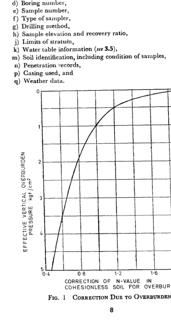
3.6 Corrections
3.6.1 Due to Overburden-The N value ior cohesionless soil shall be corrected for overburden as per Fig. 1 (Jv’ ).
3.6.2 Due to Dilatancy - The value obtained in 3.6.1 shall be corrected for dilatancy if the stratum consists of fine sand and silt below water table for values of N’ greater than 15, as under ( x” ):
N =15f$(JV’-l5)
4. REPORT
4.1 Data obtained in borings shall be recorded in the field and shall include the following:
a) Date of boring, b) Reference datum, c) Job identification, 7
X5:2131-1981
d) Boring number,e) Sample number, f) Type ofsampler, g) Drilling method,
h) Sample elevation and recovery ratio, j) Limits of stratuin,
k) Water table information (see 3.5),
m) Soil identification, including condition of samples, n) Penetration records,
p) Casing used, and q) Weather data.
CORRECTION OF N-VALUE IN
COHESlONLESS SOIL FOR OVERBURDEN
FIG. 1 CORRECTION DUE TO OVERBURDEN
8
IS : 2131- 1981 4.2 The data obtairlecl shall be prepared in a final form as a soil profile to show the nature and extent of the soil strata over the area under consideration.
9
IS :2131 - 1981
I
( Continuedfrom page 2 )
Members Representing
DIRECTOR, PWDRI Public Works Department, Govr rnmrnt of Uttar
EXECUTIVE ENGINEER ( DESIGN )V
Pradesh,. Lucknow
Central Public Works Department, New Dt,lhi EXECUTIVE ENGINEER ( SMRD ) Public Works Department, Government of Tamil
Nadu, Madras EXECUTIVE ENQINEER (CD) ( Alternate )
SRRI M. D. NAIR Associated Instruments Manufacturers ( India 1
PROF T. S. NA~ARAJ ( Alternafe )
Private Ltd, New Delhi SHRI T. K. NATRAJAN
LT-COL K. M. S. SAHASI
Central Road Research Institute, New Delhi Engineer-in-Chief’s Branch, New Delhi SRLEI A. K. CHATURVEDI ( Altetnate )
SERr S. K. SHOD
SHRI P. N. MEHTA ( Alternnte )
Geological Survey of India, Calcutta SHRI N. SIVA’XJnU
SHRI P. K. THOMAS ( Alternate )
Roads Wing, Ministry of Transport
SU;~~;~~DINO ENGINEER (IP), Irrigation Department, Government of
Maharashtra, Bombay
10
BUREAU OF INDIAN STANDARDS
Headquarters
Manak Bhavan, 9 Bahadur Shah Zafar Marg, NEW DELHI 110002
Telephones: 323 0131 I 323 3375,323 9402
Fax : 91 11 3234062, 91 11 3239399, 91 11 3239382
Central Laboratory :
Plot No. 20/9, Site IV, Sahibabad Industrial Area, Sahibabad 201010
Regional Offices:
Telegrams : Manaksanstha
(Common to all Offices) Telephone 6-77 00 32
Central : Manak Bhavan, 9 Bahadur Shah Zafar Marg, NEW DELHI 110002 32376 17
*Eastern : l/l 4 CIT Scheme VII M, V.I.P. Road, Maniktola, CALCUTTA 700054 337 86 62
Northern : SC0 335-336, Sector 34-A, CHANDIGARH 160022 60 38 43
Southern : C.I.T. Campus, IV Cross Road, CHENNAI 600113 23523 15
tWestern : Manakalaya, E9, Behind Marol Telephone Exchange, Andheri (East), 832 92 95
MUMBAI 400093
Branch Offices::
‘Pushpak’, Nurmohamed Shaikh Marg, Khanpur, AHMEDABAD 380001
$Peenya Industrial Area, 1 st Stage, Bangalore-Tumkur Road, BANGALORE 560058
550 13 48 839 49 55
Gangotri Complex, 5th Floor, Bhadbhada Road, T.T. Nagar, BHOPAL 462003 55 40 21
Plot No. 62-63, Unit VI, Ganga Nagar, BHUBANESHWAR 751001 40 36 27
Kalaikathir Buildings, 670 Avinashi Road, COIMBATORE 641037 21 01 41
Plot No. 43, Sector 16 A, Mathura Road, FARIDABAD 121001 8-28 88 01
Savitri Complex, 116 G.T. Road, GHAZIABAD 201001 8-71 19 96
53/5 Ward No.29, R.G. Barua Road, 5th By-lane, GUWAHATI 781003 54 11 37
5-8-56C, L.N. Gupta Marg, Nampally Station Road, HYDERABAD 500001 201083
E-52’, Chitaranjan Marg, C- Scheme, JAIPUR 302001 37 29 25
117/418 B, Sarvodaya Nagar, KANPUR 208005 21 68 76
Seth Bhawan, 2nd Floor, Behind Leela Cinema, Naval Kishore Road, 23 89 23
LUCKNOW 226001
NIT Building, Second Floor, Gokulpat Market, NAGPUR 440010 52 51 71
~Patliputra Industrial Estate, PATNA 800013 26 23 05
Institution of Engineers (India) Building 1332 Shivaji Nagar, PUNE 411005 32 36 35
T.C. No. 14/l 421, University P. 0. Palayam, THIRUVANANTHAPURAM 695634 621 17
*Sales Office is at 5 Chowringhee Approach, P.O. Princep Street, CALCUTTA 700072
tSales Cffice is at Novelty Chambers, Grant Road, MUMBAI 400007 SSales Cffice is at ‘F’ Block, Unity Building, Narashimaraja Square,
BANGALORE 560002
271085
309 65 28 222 39 71
Reprography Unit, BIS, New Delhi, India