Ethernet Service Deployment
A Comprehensive Guide to
© ALBEDO Telecom S.L. 2011 All rights reserved
Issue 1, 10/11
For any query or requirement regarding the AT-2048 E1 / Datacom tester, contact
with ALBEDO Telecom using the following contact details:
ALBEDO Telecom S.L.
C/ Joan d’Àustria 112 08018 Barcelona - Spain
E-mail: [email protected]
iii
10 Gb/s Ethernet ... 9
Optical Transmission ...10
10 Gb/s Ethernet over Copper ...12
Compatibility with SDH/SONET...14
Higher Speed Ethernet ... 16
Multilane Distribution Procedure ...17
Physical Media ...19
40 Gb/s and 100 Gb/s Ethernet over OTN...21
Chapter 2: Switched Ethernet ... 25
From Shared to Dedicated Media... 26
Ethernet Bridging ...27
Full-Duplex Operation ...30
Hands-on: Performance of Ethernet Switches with RFC 2544 ...32
Virtual LANs ... 40
Hands-on: Transparency Tests across VLANs...42
The Spanning Tree Protocol Family ... 47
Redundancy and Bridging...49
The Classic Spanning Tree Protocol ...50
Rapid Spanning Tree Protocol...54
Multiple Spanning Tree Protocol ...54
The Network Layer ... 56
The TCP/IP Reference Model...57
The Internet Protocol ...58
Internet Control Message Protocol ...62
Address Resolution Protocol ...62
Higher Layers of the TCP/IP Protocol Stack... 66
Chapter 3: Carrier Ethernet ... 71
Ethernet as a MAN / WAN Service... 73
Network Architecture...74
Ethernet Virtual Connections ...76
Multiplexing and Bundling ...77
MEF Generic Service Types...78
Connectivity Services ...80
iv Labels... 104 MPLS Forwarding Plane ... 107 Label Distribution ... 109 Martini Encapsulation... 114 Pseudowires ... 116 Ethernet Pseudowires... 122 MPLS Transport Profile ... 131 Quality of Service ... 141
QoS Control Basics ... 141
QoS In Ethernet Networks... 145
QoS in IP Networks ... 157
End-to-End Performance Metrics ... 159
Operation, Administration and Maintenance... 171
Ethernet OAM ... 171
MPLS OAM ... 178
Chapter 4: Ethernet in Access Networks ...197
Fiber to the Neighborhood ... 199
Ethernet over Telephone Copper Pairs ... 202
Ethernet in Optical Access Networks ... 203
The Need of an Optical Access Network... 204
1Gb/s and 10 Gb/s Ethernet PON... 205
PON Concepts and Alternatives... 206
EPON Particularities... 212
Chapter 5: Ethernet Mobile Backhaul Networks...221
Towards the “All-IP” Network... 223
Circuit Emulation Services ... 225
Transmission of Timing Information ... 226
Structure Aware vs. Structure Agnostic CES ... 228
Encapsulations for Structure Agnostic CES... 231
v
Appendix A : The OSI Reference Model ... 249
Seven Layers ... 250
Physical Layer... 251
Datal Link Layer... 252
Network Layer ... 254
Transport Layer ... 254
Session Layer... 254
Presentation Layer ... 255
Application Layer ... 255
Appendix B : Introduction to Ethernet ... 257
A Brief History of Ethernet ... 259
Ethernet and the OSI Reference Model... 260
PHY and MAC Layer Independence... 261
The Ethernet PHY ... 263
Legacy Ethernet Interfaces ... 263
Hands-on: Good Cabling Practices ... 268
Hands-on: Testing Auto-Negotiation... 277
The Ethernet MAC... 284
CSMA/CD... 285
The Ethernet Frames ... 289
Hands-on: Determining Support of Jumbo Frames ... 292
The Ethernet LLC ... 296
Appendix C : Time Division Multilexing ... 299
Deterministic TDM... 300
Pulse Code Modulation... 300
Channel Coding ... 301
Multiplexing and Multiple Access ... 302
Basic Rates: T1 and E1... 304
vi
Hands-on: Performance of TDM networks ... 315
In-Service and Out-of-Service Measurements... 315
Bit Error Rate ... 315
ITU-T Error Performance Recommendations ... 317
Appendix D : Timing Methods... 319
Synchronization Architectures... 320
Synchronization Network Topologies... 322
Interconnection of Nodes ... 324
Synchronization Signals... 324
Global Positioning System ... 326
Disturbances in Synchronization Signals ... 327
Frequency Offset ... 327
Phase Fluctuation... 328
Synchronization Models ... 333
Pointers and Timing Compensation... 335
Gigabit Ethernet (GbE) is known to be a good and cost-effective technology for service providers seeking to roll out Metropolitan and Campus Area Networks (MAN/CAN). 10 Gigabit Ethernet (10GbE), 40 Gigabit Ethernet (40GbE) and 100 Gigabit Ethernet (100GbE) were designed keeping MAN and WAN applications in mind (see Figure 1.1), but it can also be used for some bandwidth-consuming LAN and Storage Area Network (SAN) applications. High speed Ethernet opens up opportunities for new technologiessuch as MPLS-TP, and for applications like triple play.
Name Media Type H/F Coding Line MFS Range
Et hernet IEEE 80 2.3 a -t
10BASE-2 One 50Ω thin coaxial cable H 4B/5B Manch. 64 185 m
10BASE-5 One 50Ω thick coaxial cable H 4B/5B Manch. 64 500 m
10BROAD-36 One 75Ω coaxial (CATV) H 4B/5B Manch. 64 3600 m
10BASE-T Two pairs of UTP 3 H/F 4B/5B Manch. 64 100 m
10BASE-FP Two optical 62.5 µm MMF passive hub H/F 4B/5B Manch. 64 1000 m
10BASE-FL Two optical 62.5 µm MMF asyn hub H/F 4B/5B Manch. 64 2000 m
10BASE-FB Two optical 62.5 µm MMF sync hub H/F 4B/5B Manch. 64 2000 m
Fast E the rnet IEEE 80 2. 3u
100BASE-T4 Four pairs of UTP 3 H/F 8B/6T MLT3 64 100 m
100BASE-T2 Two pairs of UTP 3 H/F PAM5x5 PAM5 64 100 m
100BASE-TX Two pairs of UTP 5 H/F 4B/5B MLT3 64 100 m
100BASE-TX Two pairs of STP cables H/F 4B/5B MLT3 64 200 m
100BASE-FX Two optical 62.5 µm MMF H/F 4B/5B NRZI 64 2 km
100BASE-FX Two optical 50 µm SMF H/F 4B/5B NRZI 64 40 km
Gi ga bi t E the rn et IEE E 80 2. 3z, 8 0 2. 3a b
1000BASE-CX Two twinax cables H/F 8B/10B NRZ 416 25 m
1000BASE-KX PCB traces with two connectors 100 Ω H/F 8B/10B NRZ 416 1 m
1000BASE-T Four pair UTP Cat. 5 H/F 8B1Q4 4D-PAM5 520 100 m
1000BASE-SX Two 50 µm MMF, 850 nm H/F 8B/10B NRZ 416 500/750 m 1000BASE-SX Two 62.5 µm MMF, 850 nm H/F 8B/10B NRZ 416 220/400 m 1000BASE-LX Two 50 µm MMF, 1310 nm H/F 8B/10B NRZ 416 550/2000 m 1000BASE-LX Two 62.5 µm MMF, 1310 nm H/F 8B/10B NRZ 416 550/1000 m 1000BASE-LX Two 8 ~ 10 µm SMF,1310 nm H/F 8B/10B NRZ 416 5 km 1000BASE-ZX Two 8 ~ 10 µm SMF, 1550 nm H/F 8B/10B NRZ 416 80 km Table 1.1
IEEE 802.3 Ethernet versions. List of acronyms: H/F: Half-Duplex and Full-Duplex ability. MFS: Minimum Frame Size in bytes. N/A: Not applicable. MMF: Multimode Fiber. SMF: Single Mode Fiber.
Prominence of Ethernet is today stronger than ever due to some recent important industry decisions:
•
The ITU-T has defined the Optical Transport Unit 4 (OTU4) for the Optical Transport Network (OTN). The OTU4 rate (112 Gb/s) is not a 4x multiplier of the lower speed interface (OTU3, 43 Gb/s). In-stead, the OTU4 is prepared from the beginning for 100 Gb/s Ethernet.•
The transport profile for Multi-Protocol Label Switching (MPLS-TP) is a replacement of traditional Time Division Multiplexing (TDM) transport networks and specifically of the Synchronous Digital Hi-erarchy (SDH) and the Synchronous Optical Network (Sonet). MPLS-TP is not directly Ethernet but can be used to supply or ex-tend Ethernet services like E-line, E-LAN and E-Tree. High speed10G Et herne t IE EE 80 2.3 a e, 80 2.3 a k, 80 2.3 an, 80 2.3 a
p 10GBASE-CX4 Two twinax cables F 8B/10B NRZ N/A 15 m
10GBASE-KX4 PCB traces with two connectors 100 Ω F 8B/10B NRZ N/A 1 m
10GBASE-T Four pair UTP Cat. 6a F 64B/65B DSQ 28 N/A 100 m
10GBASE-SR Two 50 µm MMF, 850 nm F 64B/66B NRZ N/A 2 ~ 300 m
10GBASE-SW Two 62.5 µm MMF, 850 nm F 64B/66B NRZ N/A 2 ~ 33 m
10GBASE-LX4 Two 50 µm MMF, ~1300 nm, 4 x WDM signal F 8B/10B NRZ N/A 300 m
10GBASE-LX4 Two 62.5 µm MMF, ~1300 nm, 4 x WDM signal F 8B/10B NRZ N/A 300 m
10GBASE-LX4 Two 8 ~ 10 µm SMF, ~1300 nm, 4 x WDM F 8B/10B NRZ N/A 10 km
10GBASE-LR Two 8 ~ 10 µm SMF, 1300 nm F 64B/66B NRZ N/A 10 km
10GBASE-LW Two 8 ~ 10 µm SMF, 1310 nm F 64B/66B NRZ N/A 10 km
10GBASE-ER Two 8 ~ 10 µm SMF, 1550 nm F 64B/66B NRZ N/A 2 ~ 40 km
10GBASE-EW Two 8 ~ 10 µm SMF, 1550 nm F 64B/66B NRZ N/A 2 ~ 40 km
40G and 100 GEt h erne t IE EE 80 2. 3 ba
40GBASE-CR4 4 + 4 twinax cables F 64B/66B NRZ N/A 10 m
40GBASE-KR4 PCB traces with two connectors 100 Ω F 64B/66B NRZ N/A 1 m
40GBASE-SR4 4 + 4 OM3 MMF, 850 nm F 64B/66B NRZ N/A 100 m
40GBASE-LR4 Two 8 ~ 10 µm SMF, 1310 nm, 4 x WDM
signal
F 64B/66B NRZ N/A 10 km
100GBASE-CR10 10 + 10 twinax cables F 64B/66B NRZ N/A 10 m
100GBASE-SR10 10 + 10 OM3 MMF, 850 nm F 64B/66B NRZ N/A 100 m
100GBASE-LR4 Two 8 ~ 10 µm SMF, 1310 nm, 10 x WDM F 64B/66B NRZ N/A 10 km
100GBASE-ER4 Two 8 ~ 10 µm SMF, 1310 nm, 10 x WDM F 64B/66B NRZ N/A 40 km
Table 1.1
IEEE 802.3 Ethernet versions. List of acronyms: H/F: Half-Duplex and Full-Duplex ability. MFS: Minimum Frame Size in bytes. N/A: Not applicable. MMF: Multimode Fiber. SMF: Single Mode Fiber.
Ethernet network s are perfectly suitable as the transport infra-structure required by MPLS-TP.
Figure 1.1 Today, Ethernet finds applications in the Access, Metro and Transport networks. It works smoothly with MPLS and IP or it can be used to deliver synchronization.
UE Node-B Node-B Transport Metro Switch CPE CPE CPE CPE Access OTN OTU4 OTN OTU3 SDH / SONET STM64 / OC192 ADM VPLS PE PE PE PE PE PE PE 100GBASE-R 10GBASE-R 40GBASE-R MPLS-TP OLT / DLAM CE CE Satellite CPE CPE Triple Play IPTV IPTV Headend Enterprise VoIP Data Data LTE Sync-E CES QinQ E-Line E-LAN E-Tree EPON EFM
•
The 3GPP Long Term Evolution (LTE) cellular communications stan-dard defines a multiplay service network, the ‘All-IP’ network, suitable both for cellular and fixed services. The ‘All-IP’ network is prepared for delivery of any kind of service. With the LTE and the ‘All-IP’ network it is completed the migration of cellular network technology to packet-switching and Ethernet.•
Synchronous Ethernet is a tremendously important initiative which aims to use the Ethernet physical layer for transmission of accurate synchronization. Good synchronization is a key require-ment of many services and application, particularly for the mo-bile network. For first time, Ethernet offers a synchronization quality which is at least of the same level of TDM networks.1 Gb/s Ethernet
The Gigabit Ethernet standards were first released in 1998. The IEEE 802.3 standardization resulted in two primary specifications:
•
IEEE 802.3z (1000BASE-X) over optical fiber and STP cable.•
IEEE 802.3ab (1000BASE-T) over Category 5 UTP cable or better. 1 Gb/s Ethernet uses the same formats and protocols as its predecessors, which guarantees integration and smooth migration from earlier versions. For Gigabit Ethernet, the PHY and MAC layers were adapted for faster bit rates and new physical media.1000BASE-X Architecture
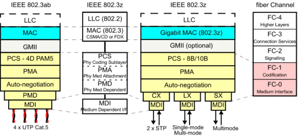
In 1998, the IEEE approved a standard for 1 Gb/s Ethernet over fiber optic cable, IEEE 802.3z. The physical layer used was the ANSI X3.230 Fiber Channel, a technology devoted to high-speed data transfer used by mainframes and servers.
There are three different versions of 1000BASE-X: 1000BASE-CX, 1000BASE-SX and 1000BASE-LX (see Figure 1.2). The first one uses an STP cable, and the second and the third one use optical fiber.
•
1000BASE-CX, designed for short interconnections of network equipment in the wiring closet. This interface is based on copper, easier to handle than fiber. It uses a 150Ω twinax cable similar to the original IBM Token Ring cabling.•
1000BASE-SX, a cost-effective interface for short backbones or horizontal cabling. This PHY is based on inexpensive 850 nm pho-todiodes and MMF. The reach ranges from 220 to 750 m.•
1000BASE-LX, targeted at longer backbones and vertical cabling. This interface is based on 1310 nm lasers, and runs over an SMF or an MMF. The reach of this PHY is 5000 m for SMF, and between 550 and 1000 m for MMF.Some manufacturers include the 1000BASE-ZX interface in their equipment. This is a non-standard interface for Gigabit Ethernet that operates on 1550 nm lasers over SMF. This interface can reach
PCS
Phy Coding Sublayer
PMA
Phy Med Attachment
PMD
Phy Med Dependent
MDI CX MDI LX MDI SX GMII (optional) PCS - 8B/10B PMA Auto-negotiation Gigabit MAC (802.3z) 2 x STP Single-mode Multimode LLC (802.2) MAC (802.3) CSMA/CD or FDX MDI
Medium Dependent I/F
FC-4 Higher Layers FC-3 Connection Services FC-0 Medium Interface FC-2 Signalling FC-1 Codification
IEEE 802.3z IEEE 802.3z fiber Channel
LLC MDI PMD PCS - 4D PAM5 PMA Auto-negotiation 4 x UTP Cat.5 IEEE 802.3ab GMII MAC LLC Multi-mode
Figure 1.2 Gigabit Ethernet defines several transmission media, specified in the IEEE 802.3z (1000BASE-X) and 802.3ab (1000BASE-T). The first one is based on the existing fiber channel technology and covers three different types of media, and the second one uses the popular UTP cable.
up to 80 km without repeaters, and it is well-suited for MAN and WAN applications.
The 1000BASE-X interface uses 8B/10B encoding followed by a simple Non-Return to Zero (NRZ) modulation. When data is ready to be transmitted, each 8-bit data byte is mapped into 10-bit symbols (8B/10B block-coding system) for serial transmission. Additional codes are included for control reasons. The channel rate of 1000BASE-X is 1250 Mb/s, and the data rate is 1000 Mb/s, due to the use of the 8B/10B encoding method.
The 8B/10B encoding method is the basis of the ANSI Fiber Channel standard for high-performance mass-storage devices, and it has properties such as excellent transition density – that is, a high number of transitions from the logic 1 to logic 0 state, which the PLL circuits require to recover the clock. It inherits excellent DC balance – there is no accumulation of DC offset that might cause the DC baseline to wander in the receiver. Furthermore, 8B/10B has
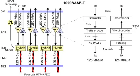
Figure 1.3 1000BASE-T transmits and receives signals simultaneously over the same pairs.
GMII PMA PMD PCS T Tx Hybrid R Rx 125 MBa u d T Hybrid R 125 MBa u d T Hybrid R 125 MBa u d T H R 125 MBa u d T Hybrid Clock Slave
Four pair UTP-5 FDX MDI 1000BASE-T Trellis encoder 9 bits 8 bits 4 symbols 8 bits 4D PAM-5 Scrambler Viterbi decoder Filtering Descrambler Tx Rx Tx Rx 125 Mbaud 125 Mbaud 250 Mb/s 250 Mb/ s 250 Mb/ s 25 0 Mb /s error recovery 250 Mb/ s 250 Mb/s 250 Mb/s 250 Mb/ s
excellent error detection capabilities and provides reliable synchronization and clock recovery.
1000BASE-T Architecture
A twisted-pair version was introduced by the IEEE in 1999 under the name IEEE 802.3ab. The physical layer was specified as UTP Cat. 5 cabling to guarantee easy integration with existing 10BASE-T and 100BASE-T networks. 1000BASE-T over UTP is usually the preferred option for horizontal cabling and desktop connection. This is an alternative to 1000BASE-CX, which is rarely used in practice.
1000BASE-T operates over Cat. 5 (or better) cabling systems by using all four pairs, sending and receiving a 250 Mb/s data stream over each of the four pairs (4 x 250 Mb/s = 1 Gb/s) simultaneously (Figure 1.3). Hybrid circuits are used to enable bidirectional transmission and reception over the same pair. These circuits perform sophisticated Digital Signal Processing (DSP), filtering, and equalization of the received signal. They also perform echo canceling and remove crosstalk, to compensate for distortion from the UTP wiring.
Figure 1.4 Power Spectrum Density (PSD) for 10/100/1000BASE-T electrical technologies.
k 20 1000BASE-T 100BASE-TX 100BASE-T2 10BASE-T 40 60 80 100 120 140 160 180 200 220 240 0 -50 -40 -30 -20 -10 -0 10 20
Cat. 3 limit Cat. 5 limit
Frequency (MHz) PSD (dB)
The 1000BASE-T PHY uses an 8B1Q4 encoding followed by a 4D-PAM5 line modulation to achieve a 250 Mb/s throughput using baseband signaling at 125 MBaud. It achieves a half-duplex data rate of 1 Gb/s at a spectral power density similar to that of 100BASE-TX (Figure 1.4).
10 Gb/s Ethernet
In June 2002 was approved the IEEE 802.3ae standard for transmission of Ethernet at 10 Gb/s. This standard made Ethernet suitable for WAN applications for the first time. In fact, compatibility and convergence with current WAN technologies is one of the most attractive features of 10 GbE. After IEEE 802.3ae was published, other standards completed the original specification: New Ethernet interfaces operating at 10 Gb/s are defined in IEEE 802.3ak, 802.3an and 802.3aq. Some important features of the 10GbE standards are:
•
Half duplex has been abandoned and only full-duplex operationis permitted. This makes CSMA/CD unnecessary.
•
Copper transmission was discarded in IEEE 802.3ae. However, more recent IEEE standards define copper transmission interfaces for twinax cables, twisted pairs and backplanes operating at 10 Gb/s.•
The 64B/66B coding is widely used by the PCS sublayer of 10GbE interfaces. This code has similar functions as the 8B/10B code used in the 1 Gigabit Ethernet. It makes frame delineation, clock recovery and single or multiple error detection possible at the physical layer. The 64B/66B encoding makes the signaling rate slightly higher than 10 GBaud. Specifically, the signaling rate of 64B/66B signals is 10.3125 GBaud.Despite all these new features, 10GbE still is Ethernet. This is why it interfaces so easily with lower rate Ethernet, and the deployment of 10GbE is less costly than that of other WAN technologies.
Optical Transmission
The interfaces defined in IEEE 802.3ae are LX4, 10GBASE-S, 10GBASE-L and 10GBASE-E (see Table 1.2). There are two versions, R and W, of each of the last three. The W version is partially compatible with SDH/SONET interfaces, and thus it is specially suitable for a connection with WAN interfaces (see Figure 1.5).
The 10GbE standard defines short-haul (10GBASE-S), long-haul (10GBASE-L) and very long-haul interfaces (10GBASE-E). The most suitable for WAN applications is the 10GBASE-E. The maximum range of this interface is 40 km, but some manufacturers specify longer distances than the standard.
The 10GBASE-LX4 is another important new interface. It makes use of a low cost version of the Wavelength Division Multiplexing (WDM) technology called Coarse WDM (CWDM). The CWDM of the
10GBASE-R Reconciliation Sublayer (RS) WIS MAC Control IEEE 802.3ae LLC MAC OSI model Application Presentation Session Transport Network Data link Physical 1 2 3 4 5 6 7 PCS 64B/66B PMA MDI PMA PCS 64B/66B PMD MDI PMD 10GBASE-X MDI PMA PCS 8B/10B PMD 10GBASE-W
XGMII XGMII XGMII
10GBASE-LX4 interface is used to multiplex four wavelengths near the second optical transmission window (1310 nm). The 10GBASE-LX4 PMD does not use 64B/66B coding. It instead transports 8B/ 10B, NRZ coded signals operating at 3.125 GBaud in each wavelength.
The maximum range of the 10BASE-LX4 is 300 m over 500 MHz * km, 50μm MMF. This is not enough for MAN or WAN applications, but it can be very useful to upgrade installed MMF to 10 Gb/s.
Interface Fiber Wavelength Modal bandwidth Range 10GBASE-LX4 62.5μm MMF ~ 1300 nm 500 MHz*km 2 ~ 300 m 62.5μm MMF ~ 1300 nm 400 MHz*km 2 ~ 240 m 50μm MMF ~ 1300 nm 500 MHz*km 2 ~ 300 m 10μm SMF ~ 1300 nm - 2 ~ 10 km 10GBASE-S 62.5μm MMF 850 nm 160 MHz*km 2 ~ 26 m 62.5μm MMF 850 nm 200 MHz*km 2 ~ 33 m 50μm MMF 850 nm 400 MHz*km 2 ~ 66 m 50μm MMF 850 nm 500 MHz*km 2 ~ 82 m 50μm MMF 850 nm 2000 MHz*km 2 ~ 300 m 10GBASE-L 8 ~ 10μm SMF 1310 nm - 2 ~10 km 10GBASE-E 8 ~ 10μm SMF 1550 nm - 2 ~40 km
Table 1.2 Range of Optical 10GbE interfaces.
Lane Wavelength margin #1 1269.0 ~ 1282.4 nm #2 1293.0 ~ 1306.9 nm #3 1318.0 ~ 1331.4 nm #4 1342.5 ~ 1355.9 nm
10 Gb/s Ethernet over Copper
Despite the initial lack of support copper transmission media in IEEE 802.3ae, later standards like the IEEE 802.3ak, 802.3an and 802.3ap fixed this situation.
IEEE 802.3ak, released in 2004 defines the 10GBASE-CX4, that constitutes the electrical counterpart of the previous 10GBASE-LX4. Like the 10GBASE-LX4, the 10GBASE-CX4 uses 8B/10B coding and transmits information over four parallel lanes. However, the 10GBASE-CX4 operates on twinax cable assemblies of up to 15 m rather than on optical fibre. The 10GBASE-CX4 standard responds to the broad demand for high-speed interconnects within wiring closets, 10GBASE-CX4 also can be used in data centers to aggregate servers.
Perhaps the most relevant standard for copper communication applications at 10GbE is the IEEE 802.3an, released in 2006. This standard defines the 10GBASE-T interface for transmission of 10Gb/ s over category 6a cables or better with range of 100 m.
The 10GBASE-T employs some mechanisms already available in 1000BASE-T. However, the 4D-PAM5 line modulation, successfully applied to GbE, does not provide the required performance level on the bandwidth supplied by cabling systems and the transmission rate of 10 Gb/s. Therefore IEEE developed a new coding and modulation scheme.
The 10GBASE-T PHY encodes the data from the upper layers with a 64B/65B code. The 64B/65B blocks are then placed in a Low Density Parity Check (LDPC) frame. The modulation uses an structure known as Double SQuare 128 (DSQ 128). The DSQ 128 symbols are generated by grouping symbols from 16-level PAM (PAM16) modulated signals in pairs. From the resulting 256 (16x16) point constellation, one half are removed in such a way that the distance from the original matrix is increased in a factor of (see Figure 1.6). This provides a 3 dB improvement in the
Noise Ratio (SNR) which leads to a significant improvement of the Bit Error Ratio (BER).
Each pair in the 10GBASE-T cable carries a PAM16 signal with a symbol rate of 800 MBaud which requires around 400 MHz of transmission bandwidth. This is not available in Cat. 5 and Cat. 5e or even in Cat. 6 cables used for 1GbE. For this reason, the new cable categories, starting with Cat. 6a have been qualified for transmission of 500 MHz bandwidths or more.
Standard IEEE 802.3ap, published in 2007, defines interfaces for Ethernet backplanes. The 10GBASE-KX4, based on the 10BASE-LX4 and 10GBASE-CX4, delivers 8B/10B encoded signals over four lanes with a signalling rate of 3.125 GBaud per lane. The 10GBASE-KR, similar to the 10GBASE-SR, 10GBASE-LR and 10GBASE-ER, transmits 64B/66B signals over a single serial transmission medium. The signalling rate in this case is 10.3125 GBaud. The IEEE 802.3ap
Figure 1.6 The DSQ 128 constellatiion is built with two PAM-16 symbols. Alternate points the resulting 256 symbol constellation are chosen such as in a chess board. The resulting constellation has 128 symbols that can be encoded by 7-bit words.
(-15, -15) (+13, -15)
(+13, -15) (+13, +15)
2d
defines also one interface for backplanes operating at 1 Gb/s, the 1000BASE-KX.
These interfaces are defined to be used in blade servers and routers/switches with upgradable line cards. IEEE 802.3ap implementations are required to operate in an environment comprising up to 1 m of copper printed circuit board.
Compatibility with SDH/SONET
The 10GBASE-W interfaces included in the 10GbE standard can be connected directly to the STM-64/OC-192 ports of the SDH/SONET access equipment. So, an Ethernet switch can be connected to the SDH/SONET network without the need of any special adaptation device. The 10GBASE-W interface makes migration to an Ethernet/ IP packet network easier, because it re-uses the existing optical WAN equipment.
Partial compatibility with SDH/SONET is achieved by means of:
•
Rate compatibility with STM-64/OC-192. The 10GBASE-Wsignal-ing rate is 9.953280 GBaud, the same as for STM-64/OC-192
•
Standard SDH/SONET framing and scrambling•
Support of a reduced set of SDH/SONET functionsTasks such as framing and scrambling are left to a special sublayer of the physical layer called WAN Interface Sublayer (WIS). The WIS takes the continuous bit stream from the PCS sublayer, mapping it into an SDH/SONET concatenated container with a self-generated
Path Overhead (POH). Then it builds an STM-64/OC-192 frame with
a fixed pointer value (522 with concatenation indication), an internally generated Multiplexer Section Overhead (MSOH) and a
SONET frame and sends the resulting bit stream to the lower sublayer (see Figure 1.7).
The available bandwidth for mapping the 64B/66B-coded Ethernet signal corresponds to the capacity of the VC4-64c / STS-192c container, 9.58464 Gb/s. This number is different from the bit rate
MSOH 577 RSOH AU ptr 1 17280 Fixed S tuf f
MAC Frame MAC Frame
HDR Payload HDR Payload MAC sublayer PCS Sublayer G1 J1 B3 C2 66 bits block WIS Sublayer POH
Figure 1.7 Mapping of 64B/66B data into a simplified STM-64 / OC-192 frame performed by the WIS in the 10GBASE-W interfaces VC4-64c / STS-192c SPE STM-64 / OC-192 B1 * A1A1*A1*A1*A1* A1*A2*A2*A2*A2*A2* A2*A2* A2*J0*Z0*Z0* X * Z0 X * XZ0* * A1 A2* A2* Z0* 1 2 3 191192193194 195 196 381382383384385386 387 575576 B2B2B2 S1 B2 B2K1 M1 K2 B2 1 2 3 191192193194 195 196 381382383384385386 387 575576
Regenerator Section Overhead
H1H1H1H1|H1 H1H2H2H2H21 2 3 H1191192193194 195 196 H2H2 H2H3H3H3381382H2383384385386 387 H3575H3576
Multiplexer Unit Overhead Administrative Unit Pointer
9 1 2 3 4 5 6 7 8
M1: Remote Error Indication (REI) H1, H2, H3: pointer bytes
Z0: reserved
K1, K2: APS protocol, fixed values A1=0xF6, A2=0x28: Frame Alignment B1: Regenerator Section Bit Interleaved Parity B2: Multiplexer Section Bit interleaved Parity
J0: Section trace message J1: Path trace message
B3: Path Bit Interleaved Parity C2: Payload type (fixed to 0x1A) G1: Path status
generated by the 10GBASE-R interface (10.3125 Gb/s). However, direct switching between interfaces with WIS and without WIS is theoretically possible, the same way as Ethernet at 1 Gb/s can be switched to 100 Mb/s Ethernet.
Not every function defined for the SDH/SONET equipment is supported by the WIS. Many of the functions of the overhead bytes are either partially supported or not supported at all. Bit Interleaved
Parity (BIP) code generation and analysis, a minimum set of SDH/
SONET alarms and path trace messages are supported. On the other hand, SDH synchronization is not supported. This means that it is not necessary to synchronize the Ethernet equipment with a central clock in the same way that is done with SDH/SONET devices. Therefore, Ethernet equipment continues being asynchronous. Low-rate container multiplexing and protection switching are not supported either. The transmitter does not need a pointer processor, but it is needed at the receiver end, because pointer adjustments may occur within the SDH/SONET network, and the receiver still needs to be able to demap the tributary signal. The Physical Media Dependent (PMD) layer for the 10GBASE-W interfaces is the same as for the 10GBASE-R interfaces. The SDH/ SONET specification is not followed at this level. The objective is to be able to manufacture inexpensive Ethernet equipment competitive with other WAN technologies.
Higher Speed Ethernet
In 2006, the IEEE 802.3 working group formed the Higher Speed Study Group (HSSG). The result of the HSSG efforts is the standard IEEE 802.3ba, ratified on June of 2010. The HSSG determined that two new rates were needed: 40 Gb/s for server and computing applications and 100 Gb/s mainly for service provider networks. Like all the lower rate Ethernet standards, the new interfaces preserve the MAC frame format defined in all other IEEE Ethernet
standards. The Physical Coding Sublayer (PCS) adopted in all the new interfaces include 64B/66B coding already used in the 10 Gb/s Ethernet PCS. The IEEE 802.3ba standard also defines new PMD sublayers for SMF, MMF and copper media.
An important new feature of 40Gb/s and 100Gb/s Ethernet is that, unlike all other Ethernet versions (or at least most of them), Higher Speed Ethernet has been designed for parallel data transmission. That means that, the 40 Gb/s or 100 Gb/s data flow is split over parallel physical paths or WDM wavelengths.
Multilane Distribution Procedure
All current PMDs for 100 Gb/s and 40 Gb/s are based on parallel transmission. Many different configurations are supported and future development of optical technologies are considered by the standard. Furthermore, the protocol stack is defined in such a way that new media and data distribution across paths in the PMD does not require to redefine the upper level protocol layers. The mechanism defined in IEEE 802.3ba to ensure flexible data distribution over the physical transmission media is the Multilane Distribution (MLD) procedure.
The MLD scheme implemented in the PCS is fundamentally based on a striping / regrouping the 66-bit blocks resulting from the 64B/ 66B encoding following a round robin algorithm. Each of the groups resulting from the MLD striping is called a lane. All bits from a lane are always transmitted over the same physical transmission medium. Periodically, unique alignment blocks are added to each lane to allow deskew in the receiver.
With the help of the MLD methodology, the encoding, scrambling and deskew functions can all be implemented in a CMOS circuit, which is expected to reside on the host device. Minimal processing
of the data bits happens in the high speed electronics embedded with an optical module.
The PCS generates a fixed number of lanes (for a fixed rate, either 100 Gb/s or 40 Gb/s) that is multiplexed before transmission by the PMA sublayer to the number required by the PMD. For 100 Gigabit Ethernet, the PCS generates 20 lanes. The number of electrical or optical interface widths supportable in this architecture is equivalent to the number of factors of the total PCS lanes. Therefore, 20 PCS lanes support interface widths of 1, 2, 4, 5, 10 and
Figure 1.8 Some lane configurations: (a) Configuration for 100 Gb/s Ethernet operating over MMF or copper. (b) Configuration for 100 Gb/s Ethernet over SMF. (c) Configuration for all 40 Gb/s currently defined interfaces. (d) 40G/bs over a single optical interface (configuration not included in IEEE 802.3ba).
(a) (b) (c) (d) 20 10 20 20 4 20 4 4 4 4 1 4 PMA/PMD PMA/PMD PMA/PMD PMA/PMD PMA/PMD PMA/PMD PMA/PMD PMA/PMD PCS PCS PCS PCS PCS PCS PCS PCS
20 channels or wavelengths. For 40 Gigabit Ethernet 4 PCS lanes support interface widths of 1, 2, and 4 channels or wavelengths. However, not every possible configuration is found in the interfaces defined by the IEEE. Currently, there interfaces with 10 and 4 physical lanes (see Figure 1.8).
Physical Media
IEEE 802.3ba extends the Ethernet rate over backplanes and copper cable assemblies to 40 Gb/s and 100 Gb/s. The 40GBASE-KR4 extends to 40 Gb/s the rate in backplanes. This interface employs four lanes of 64B/66B encoded signals. Like all other backplane Ethernet interfaces, the reach of the 40GBASE-KR4 is 1 m. Currently, there is not a backplane Ethernet interface operating at 100 Gb/s.
The 40GBASE-CR4 and 100GBASE-CR10 are designed to operate in the same environment that the 10GBASE-CX4. These interfaces use four or ten twinax cable assemblies of up to 10 m in each direction as a transmission medium. The 40GBASE-CR4 and 100GBASE-CR10 include the same 64B/66B PCS than all other 40 Gb/s and 100 Gb/s interfaces. The result is that the signalling rate for them is 10.3125 GBaud. This is also true for other 40 Gb/s and 100 Gb/s interfaces based on 10 Gb/s physical lanes, including the ones for backplanes.
Regarding the optical interfaces, there are two kinds of them. The 40GBASE-SR4 and 100GBASE-SR10 operate over MMF in short haul links. On the other hand, 40GBASE-LR4, 100GBASE-LR4 and
40 Gb/s Interface 100 Gb/s Interface Physical Media Range
40GBASE-KR4 - SMB traces 1 m
40GBASE-CR4 100GBASE-CR10 Twinax cable 10 m 40GBASE-SR4 100GBASE-SR10 OC3 MMF 100 m 40GBASE-LR4 100GBASE-LR4 SMF 10 km
- 100GBASE-ER4 SMF 40 km
100GBASE-ER4 are designed for SMF transmission with the help of WDM technology. The 40GBASE-SR4 and 100GBASE-SR10 are more suited for data center applications due to the limited reach and the dependency on cheaper MMF and low cost optical transceivers. The 40GBASE-LR4, 100GBASE-LR4 and 100GBASE-ER4 could be used for service provider network aggregation (see Table 1.4). The short haul interfaces employ four or ten OC3 MMF in each transmission direction, depending on the nominal bit rate. These interfaces operate in the 850 nm window.
The long haul interfaces have four physical lanes and they use WDM. That means that they require only one SMF per transmission direction. In the development of the 100GBASE-ER4 specification the receiver was assumed to include optical amplification such as a Semiconductor Optical Amplifier (SOA) to compensate for the optical loss budget of 40 km of single mode fiber
The WDM interfaces use either a 10.3125 GBaud signalling rate (40GBASE-LR4) or a 25,78125 GBaud (100GBASE-LR4 and 100GBASE-ER4). The 40 Gb/s interfaces use the wavelength grid
Lane Center wavelengths Wavelength ranges #1 1271 nm 1264.5 ~ 1277.5 nm #2 1291 nm 1284.5 ~ 1297.5 nm #3 1311 nm 1304.5 ~ 1317.5 nm #4 1331 nm 1324.5 ~ 1337.5 nm
Table 1.5 Wavelength specifications employed in 40 Gb/s WDM interfaces
Lane Center frequencies Center wavelengths Wavelength ranges #1 231.4 THz 1295.56 nm 1294.53 ~ 1296.59 nm #2 230.6 THz 1300.05 nm 1299.02 ~ 1301.09 nm #3 229.8 THz 1304.58 nm 1303.54 ~ 1305.63 nm #4 229.0 THz 1309.14 nm 1308.09 ~ 1310.19 nm
defined in ITU-T G.694.2 for Coarse WDM (CWDM) (see Table 1.5) while the 100 Gb/s uses the so called LAN WDM grid which is based on the ITU-T G.694.1 for Dense WDM (DWDM) (see Table 1.6). All 40 Gb/s and 100Gb/s interfaces require many transmitters and receivers to work over parallel physical lanes. To allow high density connections in network devices it is of paramount importance to develop new electrical and optical transceiver modules enabled for multilane transmission. The most important of the these are the QSFP for 40 Gb/s applications, the CXP specialised in 100 Gb/s MMF applications and CFP, which supports all 40 Gb/s and 100 Gb/s interfaces defined in IEEE 802.3ba.
Finally, as higher speed electrical and optical components are developed it is expected that Ethernet will continue its development to become cheaper and more flexible. It is likely that the next steps will be the incorporation of IEEE 802.3az capabilities to reduce energy consumption of network equipment, development of 25 Gb/s signalling for 100 GbE over backplanes and copper cable applications, and definition of serial signalling specifications for 40 Gb/s and 100 Gb/s, with the later probably using some kind of phase modulation at the optical layer like the Differential Quadrature Phase Shift Keying (DQPSK).
40 Gb/s and 100 Gb/s Ethernet over OTN
Transport of 10 Gb/s over the Optical Transport Network (OTN) requires either the definition of new Optical Data Units (ODUs) and Optical Transport Units (OTUs) or the introduction of semi-transparent mappings for the existing OTN rates. The reason is that a 64B/66B encoded 10GBASE-R signal (10.3125 Gb/s) does not fit in a ODU2 (capacity of 9.99528 Gb/s). However, semi-transparent mapping do not provide enough transparency for critical applications and the introduction of the overclocked OTU2e and OTU3e adds complexity to the whole OTN hierarchy.
To accommodate the 100 Gb/s Ethernet interfaces, the OTN defines the Optical Transport Unit 4 (OTU4) operating at 112 Gb/s (see Figure 1.9). This OTN rate is specifically defined for 100 Gb/s Ethernet (the ODU4 capacity is 104.356 Gb/s and the 100 Gb/s Ethernet line rate is 103.125 Gb/s). The OTU4 makes the interconnection of Ethernet and OTN at 100 Gb/s very straightforward.
At first sight, the situation with the 40 Gb/s Ethernet looks similar that for the 10 Gb/s interfaces. The line rate of 40 Gb/s Ethernet is 41.25 Gb/s but the capacity provided by the ODU3 is only 40.15 Gb/ s. However, a simple transcoding procedure reduces the Ethernet line rate to 40.12 Gb/s. This signal is suitable for mapping into the
Figure 1.9 Transport of Gigabit Ethernet signals over OTN. The 40 Gb/s and 100 Gb/s are carried over the OTU3 (43 Gb/s) and OTU4 (112 Gb/s)
ODUflex ODU0 ODU1 ODU2 ODU3 ODU4 OTU1 OTU2 OTU3 OTU4 2.66 Gb/s 10.70 Gb/s 43.01 Gb/s 112 Gb/s Ethernet 1 Gb/s OTU2e 11.09 Gb/s OTU3e 44.58 Gb/s Ethernet 10 Gb/s LAN Ethernet 10 Gb/s WAN ODU2e Ethernet 40 Gb/s Ethernet 100 Gb/s STM64 STM16 STM256 (L) (L) (L) (L) (L) (L) (L) ODU1 ODU2 ODU3 ODU4 (H) (H) (H) (H) GFP-F mapped Ethernet ODU3e (H)
ODU3. No new OTN rates and interfaces are therefore required. Transcoding of 64B/66B encoded 40 Gb/s Ethernet signals to the more efficient 512B/513B code is described in ITU-T G.709 Annex B.
Selected Bibliography
[1] IEEE 802.3-2008, “Part 3: Carrier sense multiple access with collision detection (CSMA/ CD) Access Method and Physical Layer Specifications”, December 2008.
[2] ITU-T Rec. G.709/Y.1331, “Interfaces for the Optical Transport Network (OTN)”, Decem-ber 2009.
[3] Rich Seifert, Gigabit Ethernet Technology and Applications for High/Speed LANs, Addi-son Wesley Oct 1999
[4] Kevin L. Paton, Gigabit Ethernet Test Challenges, Oct 2001 Test and Measurement World Magazine.
[5] Robert Breyer, Sean Riley, Switched, Fast and Gigabit Ethernet, 3rd edition 1999. [6] Millán R., Esfandiari S., “40 y 100 Gigabit Ethernet,” BIT Magazine, no. 179,
February-March 2010, pp. 46-48.
[7] Cole C., Huebner B., Johnson J., “Photonic Integration for High-Volume, Low-Cost Appli-cations,” IEEE Communications Magazine, March 2009.
Chapter 2
Switched Ethernet
Ethernet has evolved dramatically since the first card was shipped demonstrating a great ability to answer to new challenges as well as to the growing business needs.
Ethernet was originally defined as a shared-media technology, where all the stations had to compete to get access to the common transmission medium. However, this limitation no longer exists, as new versions have been developed where stations do not need to compete for resources such as media or transmission capabilities.
From Shared to Dedicated Media
Sharing media means to share not only bandwidth but also problems. A simple discontinuity in a 10BASE-2 or 10BASE-5 cable could mean that all the attached devices are unavailable. 10BASE-T addressed this problem by dedicating a cable to each station and connecting all of them to a hub (Figure 2.1). The first hubs were only central points of the cabling system, but soon enough intelligence was added to detect anomalies and to disconnect faulty stations.
Figure 2.1 First implementations of Ethernet used shared tram.ission media that evolved to dedicated media when hubs were introduced
Dedicated media Shared media
One of the fundamental issues of CSMA/CD within a shared-bandwidth medium is that the more traffic there is on the network, the more collisions there will be. That is, when the use of the network increases, the number of collisions increases as well, and the network could become unmanageable or even collapse (Figure 2.2). To solve this problem, Ethernet switches and bridges were introduced. These devices forward MAC frames by means of MAC addresses, and make better use of transmission resources than hubs based on frame broadcasting.
To cut down on the number of collisions, the first step is to use segmentation by means of bridges. Switches subdivide the network into multiple collision domains. This reduces the number of stations competing for the same resource. The second step is to dedicate one segment to those stations that have high bandwidth requirements. The final step is to configure a network that is totally switched (Figure 2.3). In this type of networks, each station has its own collision domain. Collisions are thus impossible, and each station gets to use the whole bandwidth (so, it is not shared). Those
10 Ethernet Throughput (Mb/s) Frame Size 64 bytes Frame Size 1024 bytes 8 6 4 2 10 100 Number of Hosts 40 20 10 100 Frame Size 64 bytes Frame Size 1024 bytes Dropped Frames (%) Number of Hosts 60 80 1 1
Figure 2.2 Shared Ethernet collapses as the number of hosts increases. Optimum performance is obtained for three or four stations.
Ethernet networks where each station has its own collision domain are called micro-segmented networks.
Ethernet Bridging
Bridging is a forwarding technique for packet-switched networks that makes no assumptions about where in a network a particular station is located. Instead, broadcasting is used to locate unknown devices. Once a device has been located, its location is recorded in a switching table to preclude the need for further broadcasting. Ethernet switches and bridges use bridging as specified in standard IEEE 802.1D.
Bridge
Segment B
Figure 2.3 Segmentation and switching. (a) Shared Ethernet with bus topology. (b) Segmented Ethernet. (c) Microsegmented Ethernet. Segment A Segment C One segment Switch Switch Switch (a) (b) (c)
Both switches and bridges contain a table that is used to switch Ethernet frames to the right output interface. These tables store pairs of destination addresses and associated output interfaces. When a frame enters the switch in a specific interface, the destination MAC address is checked:
1. If the address is found in the switching table, the frame is deliv-ered to the associated output interface.
2. If the address is not found, the frame is broadcast to all the output interfaces except the incoming one.
The source MAC address is also checked for every incoming frame: 1. If the address is not found in the switching table, it is stored in the
table and associated to the incoming interface. This prevents broadcasting when the same address is found in the destination field of other frames.
2. If the address is found in the switching table, no action is needed. An Ethernet bridge can be considered an Ethernet switch with only two ports. Historically, bridges appeared before switches.
In micro-segmented networks, each station is connected to a switch port. Switching eliminates the possibility of collisions, making CSMA/CD unnecessary (see Figure 2.4). More precisely:
Figure 2.4 Segmentation reduces the probability of collision; full-duplex and switching removes it completely. 1 2 3 4 5 6 7 8 9 0 Switch
• The carrier-sense protocol is not needed, because the media is never busy, as there is a link dedicated for each transmitter/re-ceiver couple.
• The collision detection protocol is not needed either, because collisions never happen, and no jamming signals are needed.
Full-Duplex Operation
To guarantee access to the media, it is important that simultaneous transmission from and reception by the same station occurs without any interference. The classic half-duplex (HDX) operation of Ethernet can be replaced by full-duplex (FDX) operation (see Figure 2.5). A station connected to a 100BASE-T interface can transmit at 100 Mb/s bit rate and receive data simultaneously at 100 Mb/s
Furthermore, in switched Ethernet networks, distance limitations are removed. Note that in shared networks, distance and frame size were restricted to allow stations to detect collisions while transmitting. In FDX systems the distance between stations
depends on the characteristics of the media and the quality of the transmitters; predefined limits do not apply.
One side-effect of full-duplex occurs when a transmitter that is constantly sending packets may cause the receiver buffer to overflow. To avoid this, a pause protocol was defined. It is a
Figure 2.5 FDX operation enables two-way transmission simultaneously without contention, collisions, extension bits or retransmissions. The only restriction is that a gap must be allowed between two consecutive frames. FDX also requests flow control, which is transmitted by the receiver to request that the transmitter temporarily stops transmitting.
Physic al MAC Inter fa ce Rx Tx Ph ys ic a l MAC Int e rf ac e Rx Tx Tx buffer Rx buffer Rx buffer Tx buffer
Frame gap Frame gap Frame gap Frame
Frame gap Frame gap Frame gap Frame
mechanism whereby a congested receiver can ask the transmitter to stop transmission.
This protocol is based on a short packet known as a Pause frame (see Figure 2.6). The pause frame contains a timer value, expressed as a multiple of 512-bit times; this specifies for how long the transmitter should remain silent. If the receiver becomes uncongestioned before this time has passed, it may send a second pause frame with a value of zero to resume the transmission. The pause protocol operates only on point-to-point links and cannot be forwarded through bridges, switches or routers.
Figure 2.6 Pause frame, used for the flow control protocol. The unit of pause time equals to 512 bits. If pause time is 0, transmission should be stopped.
1 3 5 7 SDF (0xab) 2 4 6 8 FCS MAC DA MAC SA 1 6 6 4 7 bytes
Ethertype (MAC Control frame) 2
42 Reserved Preamble (0xaa-aa-aa-aa-aa-aa-aa) Opcode (PAUSE) Timer 2 2
Opcode: Indicates Pause frame (0x00-01) Timer: Time is requested to prevent transmission Ethertype: Indicates MAC control (0x88-08)
Gigabit Ethernet introduces the concept of Asymmetric Flow Control (AFC), which lets a device indicate that it may send pause frames, but declines to respond to them. If the link partner is willing to co-operate, pause frames will flow in only one direction on the link.
There are full-duplex operation modes for all the important interfaces that operate at 10, 100 and 1000 Mb/s. Gigabit Ethernet can run in either half-duplex or full-duplex mode. While this is true in theory, nearly all the demand for GbE is for full duplex. In spite of this, it was necessary to increase the slot time to 512 bytes, to make sure that CSMA/CD works correctly. However, if GbE is only used in full-duplex mode, CSMA/CD can effectively be removed.
CSMA/CD would impose too restrictive operation to 10GbE and higher bit rate devices. Therefore there is not half-duplex operation for them. They always run with full-duplex mode.
Hands-on: Performance of Ethernet Switches with RFC 2544
The RFC 2544 is an IETF standard that describes benchmarking tests for network devices. Vendors can use these tests to measure and outline the performance characteristics of their Ethernet switching equipment. As these tests follow standard procedures, they also make it easier for customers to make sense of the glitzy marketing-speak employed by most vendors.
The tests described in the document aim to evaluate how a device would act in a real situation. The RFC 2544 describes six out-of-service tests, which means that real traffic must be stopped and the tester will generate specific frames to evaluate throughput, latency, frame loss rate, burst tolerance, overload conditions recovery and reset recovery. The document also describes specific formats for reporting the results of these tests.
Test Conditions
All Ethernet tests should be run consistently without changing the configuration of the device, and without running a specific protocol or feature. The DUT should include the normal routing update intervals and keep frequency alive.
Which Tester to Use
A tester with both transmitting and receiving ports is recommended for these tests. The tester must include sequence numbers in the frames it transmits, so that it can check that all frames transmitted are also received back.
The RFC 2544 can be used to test Layer 2 and Layer 3 devices. For Layer 3 testing, IP packets need to be configured, including parameters such as mask and subnetworks that can be understood by routers. MAC frames must always be programmed, including parameters such as frame size, bit rate, or traffic profile.
Traffic Used in the Test
• Traffic pattern – The traffic on a real network is not constant, but occurs in bursts. The RFC 2544 suggests that the tests should be carried out using constant traffic and with test conditions traffic, i.e., repeated bursts of frames, the frames within the bursts sepa-rated by the minimum inter-frame gap.
Figure 2.7 WAN performance may be tested by setting up two identical devices connected by the appropriate short-haul versions of the WAN modems. Performance is then measured between a LAN interface on one DUT, and a LAN interface on the other DUT.
GbE NG SONET/SDH NG-SONET Ethernet Tester Tester LEDSF1F2 F3 F4 EVENT RUN HOME SUM BACK PWR DC ENTER LEDSF1 F2F3 F4 EVENT RUN HOME SUM BACK PWR DC ENTER
• Protocol addresses – The simplest way to perform these tests is to use a single stream of data. Networks in the real world do not have just one stream of data. The RFC 2544 suggests that after the tests have been run in this way, they should be re-run using a random destination address. For routers the RFC 2544 suggests that the addresses used should be random, and evenly distribut-ed over a range of 256 networks. For bridges the range should be uniformly distributed over the full MAC range.
• Maximum frame rate – When testing on a LAN, the maximum frame rate for the medium and frame size being used should be used for the test. When testing on a WAN, a rate greater than the maximum theoretical rate for the medium and frame size should be used.
• Frame sizes – The RFC 2544 recommends that the tests are carried out at a range of frame sizes - 64, 128, 256, 512, 1024, 1280, 1518 bits. This covers the range of frame sizes that are typically transmitted.
• Frame formats – The format of the frames of TCP/IP over Ethernet are specified in appendix C of the RFC.
Test Duration
These tests are designed to measure how a device will perform under continuous operation. The test time must be a compromise between this and the time available to complete a test suite. The RFC recommends that the duration of each trial should be at least 60 seconds.
RFC 2544 was designed for laboratory testing of equipment, which is why the tests as described may take several days to complete. This duration is unlikely to be possible or necessary when testing a network in the field. The time taken for the test can be reduced by selecting the tests to be run, and by reducing the number of repetitions.
Test Setup
The aim of this set of tests is to evaluate the performance of equipment in real-world situations. The RFC 2544 states that all the protocols supported by the device must be enabled when testing, and the equipment must be set up according to the instructions supplied to the user. The only changes allowed between tests are those needed to perform the different tests. It is not acceptable, for example, to change the size of the frame-handling buffer between tests of frame-handling rates.
Regarding the test reports, the RFC recommends that, in addition to the results, the following should be included in test reports: • DUT setup: which functions are disabled, which ones used • DUT software version
• Frame formats • Filter setups
Running the Trial
The RFC defines a test as being made up of multiple trials. Each trial gives a piece of data, for example the loss rate at a particular input frame rate. The following procedure describes the steps for a single trial:
1. If the device you are testing is a router, send the routing update to the input port and wait two seconds.
2. Send the trial frames to the output port. 3. Run the trial.
4. Wait for two seconds to receive all the data back. 5. Wait at least five seconds before starting the next trial.
Throughput
The aim of a throughput test is to determine the maximum number of frames per second that the device can process and forward without dropping or losing any. The procedure is as follows: 1. Send a certain number of frames at a specific rate through the
DUT and count the frames transmitted by the DUT.
2. If the count of transmitted frames is equal to the count of received frames, increase the throughput and re-run the test. 3. Re-run the test until fewer frames are transmitted than received
by the DUT.
The throughput is the fastest rate at which the count of test frames transmitted by the DUT is equal to the number of test frames sent to it by the test equipment.
Figure 2.8 RFC 2455 performance evaluation of a mutiport Ethernet: (a) Test is carried out with the help of two testers. (b) If the tester has two testing ports, all testing can be finished with a single test
DUT Ethernet Tester Loopback Ethernet Tester DUT (a) (b) Ethernet Tester LEDSF1 F2 F3F4 EVENT RUN HOME SUM BACK PWR DC ENTER LEDSF1 F2 F3F4 EVENT RUN HOME SUM BACK PWR DC ENTER LEDSF1 F2 F3 F4 EVENT RUN HOME SUM BACK PWR DC ENTER
Results must be expressed in frames per second, or alternatively in bits or bytes per second.
The statement of performance must include the following information:
• The measured maximum frame rate • The size of the frame used
• The theoretical limit of the media for that frame size • The type of protocol used in the test.
Latency
This test determines the latency inherent in the DUT. The initial data rate is based on the results of the throughput test. Typically, packets are time stamped, and the time they take to travel through the DUT is measured.
You must first measure the throughput for the DUT at each of the defined frame sizes, and send a stream of frames through the DUT at the determined throughput rate to a specific destination. The duration of the stream should be at least 120 seconds. After 60 seconds, an identifying tag should be included in one frame. The time at which this frame is completely transmitted is recorded, and this will be timestamp A. The receiver of the test equipment must recognize the tag information in the frame stream and record the reception time of the tagged frame. This will be timestamp B. The latency is the difference between timestamp B and timestamp A, according to the definition found in RFC 1242. The test report must state which definition of latency, from RFC 1242, was used for this test. The latency results should be reported as a table, with a row for each tested frame size. There should be columns for the frame size, the rate at which the latency
test was run for that frame size, for the media types tested, and for the latency values for each type of data stream tested.
Frame Loss Ratio
The aim of this test is to determine the frame loss ratio throughout the entire range of input data rates and frame sizes. The procedure is the following:
1. Send a certain number of frames at a specific rate through the DUT,
counting the frames transmitted.
The first trial should be run for the frame rate that is 100% of the maximum rate for the frame size on the input media.
The frame loss rate at each point is calculated as follows: ((input_count - output_count) * 100) / input_count
2. Repeat the procedure for the rate that corresponds to 90% of the maximum rate used, and then for 80% of this rate.
3. Continue this sequence (at reducing 10% intervals) until there are two consecutive trials where no frames are lost. The maximum granularity of the trials may be 10% of the maximum rate, although you may want to define a finer granularity.
Back-to-Back Frames
A back-to-back frame test determines the node buffer capacity by sending bursts of traffic at the highest theoretical rate, and then measuring the longest burst where no packets are dropped. This is done to check the speed at which a DUT recovers from an overload condition, and the procedure is as follows:
1. Send a burst of frames with minimum inter-frame gaps to the DUT, and count the number of frames forwarded.
2. If the count of transmitted frames is equal to the number of frames forwarded, increase the length of the burst and re-run the
test. If the number of forwarded frames is less than the number transmitted, reduce the length of the burst and re-run the test. The back-to-back value is the number of frames in the longest burst that the DUT can handle without losing any frames. The trial length must be at least 2 seconds, and it should be repeated at least 50 times with the average of the recorded values being reported. The back-to-back results should be reported as a table, with a row for each of the tested frame sizes. There should be columns for the frame size and for the resultant average frame count for each type of data stream tested. The standard deviation for each measurement may also be reported.
System Recovery
This test determines the node speed at which a DUT recovers from an overload condition. The procedure is as follows:
1. Measure the throughput for a DUT at each of the listed frame sizes.
2. Send a stream of frames at a rate that is 110% of the recorded throughput rate or the maximum rate for the media, whichever is lower, for at least 60 seconds.
3. At Timestamp A, reduce the frame rate to 50% of the above rate and record the time of the last frame lost (Timestamp B). The system recovery time is calculated by subtracting Timestamp B from Timestamp A. The test must be repeated a number of times, and the average of the recorded values is reported.
The system recovery results should be reported as a table, with a row for each of the tested frame sizes. There should be columns for the frame size, the frame rate used as the throughput rate for each type of data stream tested, and for the measured recovery time for each type of data stream tested.
Reset
This test is intended to characterize the speed at which a DUT recovers from a device or software reset. The procedure is as follows:
1. Measure the throughput for the DUT for the minimum frame size on the media used in the testing.
2. Send a continuous stream of frames at the determined throughput rate for the minimum-sized frames.
3. Reset the DUT.
4. Monitor the output until frames begin to be forwarded, and record the time that the last frame (Timestamp A) of the initial stream and the first frame of the new stream (Timestamp B) are received.
A power-interruption reset test is performed as described above, except that instead of resetting, the power to the DUT should be interrupted for 10 seconds.
This test should only be run using frames addressed to networks directly connected to the DUT, so that there is no requirement to delay until a routing update is received. The reset value is calculated by subtracting Timestamp A from Timestamp B. Hardware and software resets, as well as a power interruption should be tested.
Virtual LANs
Virtual LAN (VLAN) is a local-area network that is logically segmented on an organizational basis, by functions, project teams or applications, rather than on a physical or a geographical basis. The network can be reconfigured through software, instead of physically unplugging and moving devices or wires. Stations are connected by switches and routers (see Figure 2.9). VLANs are an
important contribution to scalable Ethernet networks, because they limit broadcast traffic inherent to the bridging mechanism. Large amounts of broadcast traffic may damage performance and even collapse network equipment, which is why it must be controlled (see Figure 2.10).
Every virtual switch remains isolated and can only be communicated to other virtual switch by a layer-3 device. Ports from different physical switches can be attached to the same VLAN, and distant stations separated by thousands of kilometers could be part of the same virtual segment. The switch knows how to process traffic from different VLANs, because each Ethernet frame transmitted between switches has a special label that carries a VLAN IDentifier (VID). The format of VLAN labels(see Figure 2.11) is defined in the IEEE 802.1Q standard.
VLANs are created to provide the segmentation of services regardless of the physical configuration of the network. VLANs include address scalability, security and network management. Routers in VLAN topologies are very important, because they
Router Hub
Router
Figure 2.9 Virtual LAN vs. Segmented LAN.
Logical segmentation with VLAN Physical segmentation
Switch Switch
provide broadcast filtering, addressing and traffic flow management.
Hands-on: Transparency Tests across VLANs
Ethernet networks with VLANs use two fields to forward frames: the destination MAC address and the VID. These networks must also have layer-3 routing mechanisms to make different VLANs communicate . As a result, the fields the network has at its disposal for forwarding packets are: Destination MAC address, Destination IP address and VID.
How does the network coordinate forwarding using these fields? VLAN configuration affects IP addressing. VLANs form separate broadcast domains. Those network interfaces that are connected to the same domain must belong to the same IP network, and they must have the same IP network prefix. On the other hand, those network interfaces that are connected to different VLANs must have different IP network prefix. In fact, this is one of the advantages of VLANs: They allow end users to keep the same IP addressing regardless of the physical port they are using. For
100
SPARC 2 CPU Performance
80 60 40 20 0 200 400
Background ARP traffic600 800 1000
Figure 2.10 Loss of performance of a workstation due to broadcast Ethernet frames transporting ARP data.
packets/s (%)
example, a network made up of three VLANs, 101, 102 and 103, could be configured with three different IP network prefixes like 192.168.101.0/24, 192.168.102.0/24 and 192.168.16.103.0/24.
When a user in a particular VLAN decides to send information to other user in the same VLAN, the network simply forwards the frames by using bridging. It may be necessary to use the ARP protocol to get the destination MAC address before transmission, but the IP layer is not used in any other way during the communication process. A switch may use flooding, if the destination MAC address is not listed in the local switching table.
Figure 2.11 Ethernet frame with 802.1Q VLAN field structure. Preamble (0xaa) bits 1 3 5 7 SDF (0xab) 2 4 6 8 FCS MAC DA MAC SA Ethertype (Q-tagged frame)
1 6 6 2 4 7 bytes
Ethernet Q-frame (IEEE 802.1Q)
Ethertype: Ethertype for VLAN frames (0x8100)
TCI: Tag control information, contains the VLAN ID and other fields T / L TCI 2 2 VL A N ta g bits 1 2 3 4 5 6 7 8 Priority CFI VID Priority: Priority bits
CFI: Canonical format indicator VID: VLAN identification tag
Flooding occurs directly in the untaggedports of the switch, but frames are also forwarded to trunk links to enable communication with those users who are connected to other switches in the same VLAN. In this case, the corresponding VID is added to the original MAC frame.
Communication between VLANs takes place when one user sends packets with a destination IP address associated to a different VLAN. The data transmitted goes through the source VLAN and arrives to a VLAN default gateway or router. The default gateway then removes VLAN tags, if necessary, and decides whether the packet is to be forwarded to a new VLAN by using a routing table. Finally, the router adds the necessary VLAN tags with the correct VID, and forwards the frame to the correct interface (see Figure 2.12). Things are similar when a user needs to send information to an external network, but in this case, the router may need to add an entirely new layer-2 encapsulation, such as PPP, to the packets, rather than remove and add VLAN tags.
Routing between VLANs can be carried out more efficiently, if the router is connected to a trunk interface. With this architecture, only one physical link between one switch and the router is used to interconnect VLANs. This connection scheme requires a router that supports the IEEE 802.1Q interface. This network interface must be configured in the router with as many IP addresses as VLANs to interconnect. Each IP address must be associated with a specific VLAN. For this interface, IP addressing must be compatible with the VLAN addressing of the network (see Figure 2.13). Some switches with layer-3 features can route traffic between VLANs without using an external router. These switches have their own routing tables, and they use the destination IP address to choose the outgoing VLAN.
All networks and network segments with VLANs should be tested before bringing them into service. Especially, it is very important to
test isolation and routing between VLANs. Isolation can be tested in two different ways:
• From a user interface. A traffic generator is connected to an inter-face associated with the VLAN under test, and broadcast traffic is generated (destination MAC address ff:ff:ff:ff:ff:ff ). A traffic ana-lyzer is connected to those network interfaces that are associated
Figure 2.12 A switch with two trunks carrying VLAN-tagged frames. One of the links connects VLAN users from different switches across the network. The other one is used for connection between VLANs and with external networks. All frames that need to change their VID must pass through this router.
Switch VLAN 101 VLAN 103 VLAN 102 Routing: - Between VLANs External Network Trunk links IEEE 802.1Q
- With external networks
Switch Switch
The Tester checks visibility between VLAN 101 and VLAN 103
LEDSF1F2 F3 F4 EVENT RUN HOME SUM BACK PWR DC ENTER
with the same and different VLANs. The test is performed to check that broadcast traffic is flooded only to those interfaces that are attached to the same VLAN.
• From a trunk interface. A traffic generator is connected to a trunk interface. Broadcast traffic is generated from the trunk interface, and the test is carried out to check that traffic is received in the VLAN expected. All VLANs can be tested at the same time with a traffic generator that has multistream generation capabilities. Several simultaneous broadcast traffic flows with different VLAN tags are then generated. The analyzers used will check that every VLAN receives the corresponding traffic flow.
Figure 2.13 Routing between VLANs. Traffic is delivered to a router. The router checks the destination IP address and replaces the source VLAN tag with the destination VLAN tag. The network then forwards the traffic to the destination by bridging.
FCS IP E th H ea der VI D = 101 VLAN frame Dat agram FC S IP Et h H ead er VI D = 10 2 VLAN frame Dat a gr am IP He ader IP source IP destination Payload IP Datagram Switch Router
To test routing between VLANs, it is necessary to use a traffic generator with IP generation capabilities. The test traffic must be addressed to an IP address in the remote VLAN to be tested. If the network has been set up correctly, the traffic will reach the router. The router then removes and adds the correct VLAN tags, and finally, the traffic will reach the traffic analyzer at the destination VLAN. There is no need to configure any of the destination MAC addresses, if the traffic generator can generate ARP requests, and if both the router and the traffic analyzer are able to answer to them. Detailed analysis of the traffic in the network should detect this ARP traffic and the test traffic as well. The inter-VLAN test traffic is unicast. This means that it will not be received in several ports at the same time. Especially, if the source and destination VLANs are in the same switch, the test traffic will not be switched to any trunk interfaces other than the one connected to the router. It will probably be possible to detect some broadcast ARP traffic in trunk links while the test is being carried out.
The Spanning Tree Protocol Family
The first Ethernet networks were implemented with a coaxial bus topology. Individual coaxial segments could be interconnected with repeaters, as long as multiple paths did not exist between any two stations.
During the 1980s, bridges and routers reduced the number of stations per segment to split traffic in a more efficient way, according to the user requirements. Separating traffic by departments, users, servers or any other criteria reduces collisions while increasing aggregated network performance.
Since the early 1990s, the network configuration of choice has been the star-connected topology. The center of the star is a hub, a switch or a router, and all connections are point-to-point links from the
center to the station. This topology has proven to be the most flexible and easy to manage in LAN networks.
New high-speed Ethernet versions have gained increasing acceptance since the year 2000, competing for the campus and metropolitan markets where point-to-point, ring, meshed physical topologies are common (see Figure 2.14).
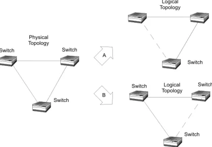
However, logical topology of pure Ethernet networks based on bridging must meet some conditions in order to guarantee proper operation. If not the physical topology, at least the logical topology must be free of loops. Otherwise, the network could become unusable.
Figure 2.14 Topology is a very general term, and only very simple networks can be classified into one topology only. Ethernet networks could be a combination of several trees interconnected to other trees and remote services as well, using different solutions such as point-to-point, multipoint or hybrid.
Bus (not used anymore) Point-to-point
Tree Point-to-multipoint Access Hybrid SONET/SDH Campus