Faculty of Engineering
Department of Electrical Engineering
Ph.D. Thesis
Chair of Electromechanical Constructions
HARMONIC CURRENT SIDEBAND INDICATORS
(HCSBIs) FOR BROKEN BAR DETECTION AND
DIAGNOSTICS IN CAGE INDUCTION MOTORS
Ph.D. Student
Claudio Bruzzese
Supervising Professor
Co-Supervising Professor
Prof. Ezio Santini
Prof. Onorato Honorati
Innanzitutto la dedico a quanti vorranno leggerla con interesse, se ve ne saranno.
La dedico a chi ha passione nella Scienza e nella Tecnica.
A chi ama la Matematica e le simmetrie in Essa celate.
La dedico a mio padre e mia madre, presenze costanti nella mia vita.
Ai miei fratelli, Davide e Simone, distanti e vicini al tempo stesso.
A tutti i miei maestri.
Al prof. Ezio Santini, con gratitudine.
Al prof. Onorato Honorati, con reverenza.
INTRODUCTION (1): ABOUT THIS WORK
INTRODUCTION (2): STATE OF THE ART
REFERENCES OF THE INTRODUCTIONS (1), (2)
1
THE SQUIRREL CAGE INDUCTION MOTOR PHASE MODEL
ACCORDING TO THE MUTUALLY-COUPLED LOOPS LINEAR
THEORY AND TRANSFORMATION BY SYMMETRICAL
COMPONENTS
1.1
INTRODUCTION: THE SYMMETRICAL THREE-PHASE CAGEINDUCTION MOTOR ELECTRICAL STRUCTURE
1.1.1
HYPOTHESES UNDERLYING THE MODEL1.1.2
STATOR WINDINGS1.1.3
ROTOR SQUIRREL CAGE1.2
ELECTRIC AND MAGNETIC EQUATIONS OF THE (n, m+1)MODEL
1.2.1
INTRODUCTION1.2.2
STATOR EQUATIONS1.2.3
ROTOR EQUATIONS1.2.4
END-RING EQUATION1.2.5
COMPLETE MATRIX SYSTEM1.2.6
PSEUDO-INDUCTANCE MATRIX AND ELECTRO-MAGNETICTORQUE
1.3
THE (n,m+1) MODEL REDUCED FORM: THE (n,m) MODEL1.4
THE SYMMETRICAL COMPONENTS TRANSFORMATION1.4.1
INTRODUCTION1.4.2
CURRENT TRANSFORMATIONS1.4.3
VOLTAGE AND FLUX TRANSFORMATIONS1.4.4
PSEUDO-INDUCTANCE MATRIX AND ELECTRO-MAGNETICTORQUE TRANSFORMATIONS
11
14
19
24
24
28
37
39
1.5.2
TRANSFORMATION OF [RSS]1.5.3
TRANSFORMATION OF [RRR]1.5.4
TRANSFORMATION OF [LSS]1.5.5
TRANSFORMATION OF [LRR]1.6
TRANSFORMATION OF GENERIC ASYMMETRICALMUTUAL INDUCTANCE RECTANGULARMATRICESBY
MEANSOFBI-SYMMETRICAL COMPONENTS
1.6.1
INTRODUCTION1.6.2
MUTUAL INDUCTANCE MATRIX COMPLEX FORM1.6.3
MUTUAL INDUCTANCE MATRIX TRANSFORMATION1.6.4
UNILATERAL SERIES-FORM FOR TRANSFORMED MATRICES1.6.5
MUTUAL PSEUDO-INDUCTANCE MATRIX TRANSFORMATION1.6.6
ELECTRO-MAGNETIC TORQUE TRANSFORMATION1.6.7
REDUCED FORM FOR THE TRANSFORMED ELECTRO-MAGNETIC TORQUE
1.7
TRANSFORMATION OF BI-SYMMETRICAL MUTUALINDUCTANCE MATRICES (CYCLIC-SYMMETRIC
MACHINES)
1.7.1
INTRODUCTION1.7.2
BILATERAL TRANSFORMATION1.7.3
UNILATERAL TRANSFORMATION1.7.4
MUTUAL PSEUDO-INDUCTANCE MATRIX TRANSFORMATION1.7.5
ELECTRO-MAGNETIC TORQUE TRANSFORMATION1.A.
APPENDIX:
FORTESQUE’S
TRANSFORMATION
FOR
CIRCULATING
MATRICES
1.A.1.
BASIC DEFINITIONS1.A.2.
TRANSFORMATION OF A COMPLEX SQUARED (nxn)CIRCULANT MATRIX BY USING FORTESCUE’S MATRICES
1.A.3.
PARTICULAR CASES OF FORTESCUE’STRANSFORMATION FOR COMPLEX SQUARED
CIRCULANT MATRICES
1.A.3.1.
MATRIX[ ]
A CIRCULANT AND REAL64
46
56
64
65
66
1.A.3.3.
MATRIX[ ]
A
CIRCULANT,REAL AND SYMMETRIC1.B.
APPENDIX:
BI-SYMMETRICAL
COMPONENTS
FOR
RECTANGULAR
( )
nxm
MATRICES
1.B.1.
GENERIC ASYMMETRICAL MATRIX SYSTEM1.B.2.
BASIC MATRIX SYMMETRICAL SYSTEM OF ORDER (p, q)1.B.3.
MATRIX SYMMETRICAL COMPONENT SYSTEM OFORDER (p, q)
1.B.4.
BI-SYMMETRICAL COMPONENTS DECOMPOSITION1.B.5.
BI-SYMMETRICAL COMPONENTS-BASEDTRANSFORMATION FOR A REAL MATRIX
1.C.
APPENDIX:
MATH STATEMENTS (miscellaneous)
1.C.1.
DEFINITIONS FOR FOURIER SERIES1.C.1.1.
DEFINITION OF REAL UNILATERAL FOURIER SERIES1.C.1.2.
DEFINITION OF REAL BILATERAL FOURIER SERIES1.C.1.3.
DEFINITION OF COMPLEX BILATERAL FOURIER SERIES1.C.2.
SOME PROPERTIES OF FORTESCUE’STRANSFORMATION
1.C.2.1.
BASIC PROPERTIES1.C.2.2.
DERIVED PROPERTIESREFERENCES
OF
CHAPTER
1
2
FAULT-RELATED FREQUENCIES CALCULATION FOR A
STEADY-STATE OPERATING MOTOR WITH BROKEN BARS
2.1
PHASE CURRENT FREQUENCIES PRODUCED BY AFAULTY CAGE
2.1.1
INTRODUCTION: PHYSICAL ASSESSMENT OF THE PHENOMENA2.1.2
FAULT-RELATED FREQUENCIES CALCULATION70
78
81
82
70
71
72
73
76
78
80
82
2.2.1
METHODOLOGY:FORTESCUE’S TRANSFORMATION2.2.2
DECOMPOSITION OF A MULTI-PHASE ASYMMETRICAL SYSTEMOF CAGE CURRENTS
2.2.3
GRAPHICAL REPRESENTATION OF SYMMETRICAL SYSTEMS2.3
SPACE HARMONICS OF AIR-GAP MAGNETIC FIELDPRODUCED BY PRACTICAL MULTI-PHASE WINDINGS FED BY GENERIC ASYMMETRIC ISO-FREQUENCY SINUSOIDAL
TIME-VARYING CURRENT SYSTEMS
2.3.1
INTRODUCTION2.3.2
HARMONIC DECOMPOSITION FOR AIR-GAP MAGNETIC FIELDS2.3.3
MAGNETIC FIELD PRODUCED BY AN ASYMMETRICAL CURRENTSYSTEM
2.3.4
MAGNETIC FIELD PRODUCED BY A SINGLE SYMMETRICALCURRENT SYSTEM
2.3.5
THE HOMOPOLAR FIELD2.3.6
THE ANTIPOLAR FIELD2.3.7
DIRECT AND REVERSE MULTIPOLAR FIELDS2.3.8
SUMMATION OF HARMONIC MAGNETIC FIELDS FORASYMMETRICAL CURRENT SYSTEMS
2.4
CALCULATION OF STATOR-LINKED FLUXES PRODUCEDBY CAGE CURRENTS
2.4.1
INTRODUCTION: CALCULATION HYPOTHESES2.4.2
STATOR-LINKED FLUX SYSTEMS2.4.3
FLUX CALCULATION FOR THE SINGLE STATOR BELT2.5
INDUCED STATOR E.M.F.S CALCULATION ANDFAULT-RELATED FREQUENCIES
2.5.1
STATOR E.M.F. SYMMETRICAL SYSTEMS AND TABLE OFFREQUENCIES FOR MONO-HARMONIC FEEDING
2.5.2
WINDING INTERNAL CONNECTION AND HIDDEN AND EXTERNALFAULT FREQUENCIES
2.5.3
FAULT FREQUENCIES IN CASE OF NON-SINUSOIDAL FEEDINGREFERENCES
OF
CHAPTER
2
119
91
106
(ETR
500)
3.1
INTRODUCTION: INVESTIGATION ABOUT MCSAAPPLICABILITY FOR INVERTER-FED FAULTED MOTORS
3.1.1
AIMS AND METHODS OF THE WORK3.1.2
SURVEY OF ROTOR FAULTS IN RAILWAYS TRACTION DRIVES3.1.3
MAIN STEPS OF THE INVESTIGATION PERFORMED3.2
HARMONIC TORQUES AND CURRENT SIDEBANDSGENESIS
3.2.1
LOCOMOTIVE E404 INVERTER DRIVE AND PULSE WIDTHMODULATION
3.2.2
SIXTH HARMONIC TORQUES3.3
MACHINE DESCRIPTION AND CIRCUITAL MODEL3.3.1
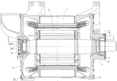
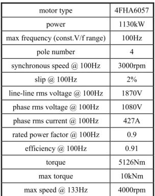
STRUCTURE AND GEOMETRY OF THE 1.13MW MOTOR UNDERCONSIDERATION
3.3.2
COMPLETE MOTOR PHASE MODEL FOR BAR BREAKAGESIMULATION
3.3.3
STATOR INDUCTANCES3.3.4
ELIMINATION OF WINDING NEUTRAL CONNECTION3.4
FINITE ELEMENTS ANALYSES AND MOTOR PARAMETERIDENTIFICATION
3.4.1
INTRODUCTION: HYPOTHESES AND REMARKS3.4.2
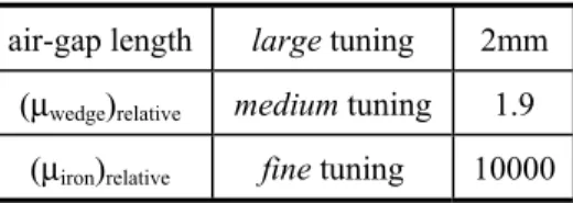
STRUCTURE PARAMETERIZATION3.4.3
STATOR INDUCTANCES IDENTIFICATION3.4.4
ROTOR INDUCTANCES IDENTIFICATION3.4.5
ROTOR-STATOR MUTUAL INDUCTANCES IDENTIFICATION3.5
MODEL REFINEMENTS AND NUMERICALIMPLEMENTATION
3.5.1
INTRODUCTION3.5.2
MATRIX PARTITION AND INTEGRATING FORM3.5.3
IMPROVING THE MODEL DIFFERENTIAL CLASS3.5.4
MODEL STABILITY3.5.5
REMARKS ON NUMERICAL ISSUES CONCERNING MACHINESIMULATION
120
120
121
124
132
144
3.6.2
LINE CURRENT SPECTRUM COMPARISON AND MATCHING3.6.3
BAR CURRENT SPECTRUM3.7
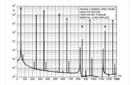
SPECTRAL ANALYSES FOR A HEALTHY MOTOR3.7.1
INTRODUCTION3.7.2
LINE CURRENT SPECTRUM COMPARISON AND MATCHING3.8
SPECTRAL ANALYSES FOR A FAULTY MOTOR3.9
CONCLUSIONS: AN INNOVATIVE APPROACH TO MCSA3.A.
APPENDIX:
CAGE
TORSIONAL
RESONANCES
IN
TRACTION
MOTORS
3.A.1.
INTRODUCTION3.A.2.
BAR BREAKAGE IN RAILWAY DRIVES3.A.3.
MEASURE OF CAGE RESONANT FREQUENCIES3.A.4.
OPTIMIZATION OF MODULATION RANGES3.A.5.
DRIVE SIMULATIONS AND SWITCHING PATTERNCOMPARISON
3.A.6.
BAR SHORTENING AND RESONANCE FREQUENCYOPTIMIZATION
REFERENCES
OF
CHAPTER
3
4
THE STEADY-STATE SOLUTION OF THE LINEAR
MODEL FOR A CAGE MOTOR WITH FAULTED BAR
AND FORMULATION OF HCSB INDICATORS
4.1
INTRODUCTION: THE STEADY-STATE SOLUTION OF THELINEAR MODEL
4.1.1
THE STEADY-STATE SOLUTION OF THE COMPLETE MODEL4.1.2
A NEW FAMILY OF BROKEN BAR INDICATORS BASED ONSPECTRAL SIDEBANDS OF SUPPLY CURRENT HARMONICS
4.2
MCSA AND NOVEL INDICATORS4.2.1
INTRODUCTION164
173
174
156
157
163
164
164
166
166
167
171
174
175
4.3.1
INTRODUCTION:FORTESCUE’S TRANSFORMATION4.3.2
CYCLIC-SYMMETRIC MACHINE MODEL4.3.3
SYMMETRICAL COMPONENTS FOR ROTOR LOOP CURRENTS4.3.4
STATOR-LINKED FLUXES4.3.5
SYMMETRICAL COMPONENTS FOR STATOR VOLTAGES ANDCURRENTS
4.3.6
ROTOR-LINKED FLUXES4.3.7
STEADY-STATE COMPLEX FORM OF THE UNBALANCED MODEL4.3.8
TRANSFORMATION AND SOLUTION OF THE UNBALANCEDMODEL
4.3.9
FORMAL DEFINITION OF BROKEN BAR INDICATORS4.4
CONCLUSIONS4.A.
APPENDIX:
NOMENCLATURE
4.A.1.
VECTORS AND MATRICES4.A.2.
SCALARS4.A.3.
SETS4.A.4.
SUBSCRIPTS4.A.5.
SUPERSCRIPTS4.A.6.
DEFINITION OF SEQUENCE PARAMETERSREFERENCES
OF
CHAPTER
4
5
EXPERIMENTAL VALIDATION OF CLASSIC AND
HARMONIC CURRENT SIDE-BAND (HCSB) INDICATORS
5.1
INDUCTION MOTOR BAR BREAKAGE EXPERIMENTATIONAND CURRENT MEASURING FOR MCSA APPLICATION BY
NOVEL FAULT INDICATORS
5.1.1
INTRODUCTION5.1.2
THE EXPERIMENTAL APPROACH187
190
192
185
187
187
188
188
188
189
192
5.2.2
PROTOTYPE PERFORMANCES5.2.3
IMPROVED CAGE5.2.4
BAR CURRENT MEASURING5.3
STATOR AND BAR CURRENT MEASURES IN BROKEN BARTESTS WITH SINUSOIDAL FEEDING
5.3.1
MEASURING CAMPAIGN AND CURRENT SPECTRA5.3.2
MOTOR PERFORMANCE DEGRADATION UNDER FAULT5.3.3
EVALUATION OF CURRENT SPECTRA WITH RESPECT TOFAULT GRAVITY AND SLIP
5.3.4
CLASSICAL FAULT INDICATORS EVALUATION5.4
STATOR AND BAR CURRENT MEASURES IN BROKEN BARTESTS WITH NON-SINUSOIDAL FEEDING
5.4.1
INTRODUCTION5.4.2
HCSB FAULT INDICATORS EVALUATION ON THEEXPERIMENTAL CAGE MOTOR
5.4.3
HCSB FAULT INDICATORS EVALUATION ON INDUSTRIALMOTORS
5.5
PROTOTYPE MOTOR MODEL IDENTIFICATION BY 2D-3DFEA AND COMPARISON OF EXPERIMENTAL, SIMULATED,
AND THEORETICAL RESULTS
5.5.1
THEORETICAL WORK5.5.2
MATHEMATICAL MODEL FOR SIMULATION5.5.3
TEST CAGE MOTOR (SIEMENS 1KW)FEMIDENTIFICATION5.5.4
TESTS FOR ACCURATE MODEL SETTING: EXPERIMENTSMATCHED WITH SIMULATIONS
5.5.5
EXPERIMENTS AND SIMULATIONS WITH BROKEN BARS:COMPARISON BETWEEN LUSBIS AND HCSBIS
5.6
CONCLUSIONSREFERENCES
OF
CHAPTER
5
CONCLUSIONS
233
234
205
212
221
232
INTRODUCTION (1): ABOUT THIS WORK
Industrial outages have a non-negligible impact on the comprehensive economic efficiency and safety of plants. One of the major aims that assimilates engineers and technicians of any time and of every technical sector (perhaps, the major aim) is just making systems and machines more and more affordable. Although the technical progress makes available always better and more durable devices, faults and out of orders are however a common reality that industrialists and manufacturers must necessarily face with. So, the reliability becomes a challenge that must be fought on other fronts too, i.e., condition monitoring, maintenance and fault management.
Condition monitoring of electrical machines and drive systems is a very important factor in achieving efficient and profitable operation of a large variety of industrial processes. The stringent requirements of modern electrical machines and drives also necessitate the application of real-time condition monitoring systems, which enable the continuous monitoring of the system under all the operating conditions, and with intelligent resources management and economic time and money savings. Safety features are non-secondary issues, and often they are the major issues. Every industrial sector (cement and paper mills, textile, chemical, iron and oil extraction plants, load movement and railway traction, etc.) can benefit by application of suitable and effective motor diagnostic techniques, since motor fault problems are often faced in inadequate way, so suffering all the negative consequences of (almost avoidable) sudden plant-stopping due to unforeseen breakdowns, [1]-[4].
Induction motor bar breakages have been increasingly studied in the last decades because of economic interests in developing techniques that permit on-line, non-invasive, early detection of motor faults in power plants (see Introduction (2)). This work is specifically focused on broken bar detection and fault severity assessment in three phase power cage motors fed by non-sinusoidal voltage sources.
Signature analysis of motor phase current (MCSA) has been usually attempted looking at (1-2s)f and (1+2s)f frequencies sidebands (the so-called lower and upper sidebands, LSB and USB respectively; s is the slip and f the feeding frequency) in the line current spectrum for rotor fault detection and fault gravity assessment, [3], [5], but the limitations of this technique have been recognized as well, [6], [7]. Many examples are available in classic and recent scientific literature about draw-backs of the existing techniques (dependence of fault indicators on causes different from the fault itself, as load variations and load fluctuations, drive inertia variations, feeding conditions and frequency changes, torque oscillations, motor parameter variations,
drive features, etc.). In particular, about MCSA technique, LSB and USB-based indicators performances are too much affected by variations of load, of drive inertia, and of operating frequency. These flaws are particularly obstructing for monitoring of drives with variable or fluctuating loads (pumps, crunchers, [3]) and inertia (railway drives, [8]), or with variable speed (fans, blowers, [9]).
Other fault indicators based on very different media (mechanical vibrations, noise, temperature, magnetic fluxes, speed and/or torque oscillations, electric power signature), generally suffer from the same drawbacks (see Introduction(2)).
So, the research is directed toward the study and application of more affordable indicators, whose performance should be (ideally) independent from any causes other than the fault and its gravity. Much effort is devoted to the development and application of new fault indicators (not only for broken bars detection), that can possibly support the existing ones to increase the potentialities of fault diagnostic techniques.
In this work some new fault indicators for rotor bar breakages detection in squirrel cage induction motors have been proposed, that were mathematically developed first, and experimentally proved afterwards, [10]-[12].
They are based on the sidebands of phase current upper harmonics, and they are well suited especially for converter-fed induction motors. The ratios I(7-2s)f/I5f and I(5+2s)f/I7f , I(13-2s)f/I11f and
I(11+2s)f/I13f are examples of such new indicators, [11], and they are not dependent on load torque
and drive inertia, as classical indicators do. Their frequency-dependence has been examined too, both theoretically and experimentally, and it was found less remarkable with respect to other indicators, [13]. Moreover, their values increase linearly with the quantity of consecutive broken bars, almost for not too much advanced faults; on 4-poles motors, really, they were found quietly like the per-unit number of broken bars (ratio on total bar number), [10].
So, the MCSA technique effectiveness is greatly improved, when applied on motors fed by low commutation frequency GTO/thyristor converters (with natural harmonics), [8], or by high commutation frequency converters (with controlled harmonic injection technique). Applications with directly line-fed motors can be attempted, since voltage distortions are often present on the plant electric grids (due to non-linearity of transformers and loads), but more sensible and precise instrumentation could be needed. However, the large current harmonics in the spectra measured in [14] (which deals with fault monitoring of induction generators in micro-hidroeletric plants) suggests that in many cases a direct application is possible.
In this Ph.D. Thesis the author will introduce these indicators by explaining first their mathematical genesis, and then by showing experimental results.
An original formulation is presented for motor mathematical modeling, based on the Multiphase Symmetrical Components Theory (MPSCT), for sidebands amplitude computation, [11], [15]. A complete motor model (involving all the elementary independent machine electrical circuits, as stator belts and rotor mesh loops) has been used for computer simulations, [8]; the same model was then transformed by using some complex Fortescue’s matrices to obtain a steady-state linear solution, solvable for stator and rotor currents, in healthy and faulty conditions, [11], [15]. By exploiting the model, the formal definition of a set of new broken bar indicators was finally obtained, [10], [11]. Machine simulations carried out by running the complete numerical model confirmed the accuracy of the model, and the theoretical previsions [8].
Experimental work was performed by using a square-wave inverter-fed motor with an appositely prepared (hand-made) cage, for easy and versatile testing with increasing number of broken bars and without motor dismounting, [16], [17]. Moreover, extensive experimentation
was carried out on three industrial motors with different power and poles number, with increasing load, frequency and fault gravity for methodology validation, [10].
A 2-D and 3-D Finite Element Method – based procedure has been carried out for motor model identification, [18]-[22]. The accuracy of parameter calculation has been verified by direct motor performance and current measures, [23], [24], [13].
Finally, the ideas exposed in the work here reported flowed to a patent application, with the legal aid of the University of Rome “Sapienza”, [25].
INTRODUCTION (2): STATE OF THE ART
Over the past few years, industrial practices have evolved from a strategy of routine scheduled maintenance (RSM) of electric equipment to condition-based maintenance (CBM) [26]. In the CBM approach, equipment maintenance based on a routine schedule can be replaced with an approach based on system wellness diagnostics. This approach (also known as ‘predictive maintenance’) might rely on non-invasive on-line monitoring of three-phase induction motors to report equipment condition and enable maintenance intervention before a failure occurs. The CBM practices have been developed and applied in many different sectors, such as mining industry [27], power generating plants [28], [1], [14], petrochemical industry and gas terminals [2], paper mills [3], wind farms [29], to name a few. A similar systematic evolution can be easily forecasted in railway public transportation, since more and more exigent safety standards can benefit by a more precise and real-time knowledge of the rolling stock wear status [8].
On the other hand, the CBM approach requires more effective motor diagnostic tools, and so an increasing research effort has been consequently devoted to the development of affordable fault indicators, [1]-[8], [26]-[32].
SOME HINTS ON THE STATE OF THE ART OF RESEARCH IN MOTOR DIAGNOSTICS
Researchers have nowadays reached an high degree of specialization in the field of electric machine and drive diagnostics, and particularly about induction machines. This is a natural consequence of the complexity of the electro-mechanical converter and of the variousness of its operating conditions. After nearly three decades of studies, detailed investigations have been carried out about faults occurring in the stator (turn-to-turn, phase-to-phase, phase-to-ground winding shorts, core lamination hot spots, displacement of conductors, etc., [30], [4]), in the main supply (unbalanced feeding, [31]), in the rotor (misalignments and air gap eccentricities, [32], conductor breakages, [1], [4], [6]), in the bearings (weariness and mechanical damage, [1], [33]) and in the load [34], and many detection techniques applicable in various particular conditions have been proposed and experimented. References [1], [4], [6], [30], [42], provide excellent surveys about motor faults and classical and recent monitoring techniques.
Few papers try to propose improbable “universal” approaches to motor diagnostics, whereas many more focus on well defined fault eventualities or on particular aspects of the diagnostic process. This is perfectly understandable, thinking to the complexity of the research field. The considerations reported here below can help to clarify the actual asset of the field.
The process of motor fault detection can be ideally subdivided into four main steps [6]:
signal measurement (acquisition of currents, vibrations, etc.); signal conditioning (measured quantities undergo a transformation such as FFT, [3], [5], wavelet analysis, [36], Wigner
distribution, [37], [38], space vector [39], higher order spectra [40], or a combination of them [41]); then an evaluation method is applied, implemented by using elaboration tools such as expert systems [42], [35], neural networks [43], [34], Fuzzy Logic [42], or motor models [44], to achieve the final goal of fault severity assessment, which furnishes actual information on the motor health status and possibly an estimation of the remaining life-time or a risk index for continued operation.
Any one of the four mentioned stages have been object of in-depth study, since they are differently focused, and each one presents particular challenges for research. They are briefly described in the following, for a better reasoned collocation of the contribution of this thesis. The signal measurement requires the choice of the physical variables (one or more, e.g. current, temperature, flux, etc.) whose value or time-evolution is expected to contain the information (symptom, or signature) related to the fault (e.g. the well-known twice-slip frequency sidebands around the fundamental component in the line current of a motor with broken bars). Sometimes, the symptom itself produces a clear external phenomenological manifestation of the fault (e.g. current amplitude modulation, or audible vibrations and noise), but not always, and neither is it necessary. Obviously, the most showy symptoms have been studied and used in machine monitoring for first in the time (as audible vibrations, [45]), but many other have been successively discovered (generally by analysing mathematical fault models, [46]-[48], [11], [5]). So, the second stage (signal conditioning) is directly functional to the choice of the selected symptom(s), since it is devoted to make evident and to measure the symptom itself (that is, until now, a physical quantity), or its time-evolution. This is called “signature extraction”. At this stage, the research is mainly devoted to the development of effective tools as far as regard speed of extraction (e.g. fast DFT for on-line algorithms, [49]), accuracy and precision (e.g. high-resolution FFT, [3]), noise suppression [50], symptom separation (sometimes different faults produce analogous or superimposed symptoms, as those produced by broken bars, load torque oscillations, or rotor misalignment; for example, the Wigner distribution has been successfully used to distinguish between symptoms due to rotor eccentricity or to load torque oscillations, [37]), and ability to track symptoms in rapidly variable transients (e.g. wavelet used to analyse motor start-ups, [36]). It is only remarked here that the advanced elaboration tools such as those used in [41], [36], are often mainly aimed to extend the use of known physical symptoms (classically performed under steady-state conditions) to non-stationary conditions, where the classical FFT fails.
The successive steps, which involve an evaluation method directly finalized to the fault severity assessment, are by scope and means, much more complex issues. At these stages, the selected and measured symptoms must be used to decide about the machine status. So, the relation existing between the symptom(s) value or trend and the eventual fault(s) must be examined and clarified, as well as the influence of the operating conditions and of other parameters or variables not directly linked to the fault (e.g., the drive inertia has been recognized to heavily influence the sideband amplitudes in MCSA). This task is usually attempted by derivation of proper indicators, obtained by processing the raw symptoms, with the aim to obtain a quantification of the fault. The difficulty is that, in general, every symptom can be regarded as an output of a complex non-linear dynamical system, which can “reflect” more or less affordably the internal machine status, but which is fundamentally function of many and often unknown parameters, and of the system inputs and external disturbs. The problem has been addressed by model-based [44] and parameter estimation [51] approaches, which exploit the system’s determinism. In alternative, AI-based tools such as neural networks and expert systems endowed with knowledge bases (which combine both empirical and theoretical knowledge) may help to condense the operator’s experience to realize the fault diagnosis, so contributing to overcome the system complexity [35], [42], [43].
These considerations clarify the great importance of singling out fault symptoms with high rejection to extraneous influences, to simplify the processing stages following the raw measure in the monitoring process [6]. In the following section a short review of the currently most
known broken bar symptoms is given, with particular attention to this aspect of their performances.
BRIEF REVIEW OF BROKEN BAR SYMPTOMS MOST USED IN DIAGNOSTIC PRACTICES
Rotor fault of electrical origin, such as broken or cracked rotor bars and end rings give rise to specific fault-related patterns in the electrical, electromagnetical, mechanical quantities and acoustic emission, as reported here below.
A. Electromagnetic symptoms:
a) Current: MCSA, usually performed by FFT, is based on the evaluation of the typical current sidebands located at ±2ksf around the fundamental line (k is an integer), and in particular of the previously described USB and LSB; the measure of only one current is needed, but LSB and USB both must be measured and summed to obtain results quite independent from drive inertia [5]. Anyway, sideband amplitude depends on load torque level, [6], [7], [3], [35], on the particular motor parameters and power ratings [28], on manufacturing asymmetries [35], on constructive details (as spidered rotors, [28]), and eventually on motor feeding frequency [13]. Load dependency, for example, is a physical phenomenon evident enough. Once the load of an induction machine is removed, rotor currents almost vanish. Therefore, the reaction of a rotor fault on the air gap field and the signatures in the stator current almost disappear, too. Theoretical and experimental evidences of some of these drawbacks have been also given in this work. In addition, load torque fluctuations and speed oscillations produce sidebands similar to LSB and USB, so a mismatch is a concrete possibility, especially in drives with mechanical gear couplings. In certain drives, the low-frequency mechanical oscillations arising from a stage of the gear coupling make the correspondent current sidebands to completely superimpose to LSB and USB, [3]. So, an high-resolution spectral analysis is often required, together with particular methods for removing the load torque oscillation effects from the current spectrum, although additional information may be required through multiple acquisition channels (e.g., currents and voltages), [52]. Moreover, it must be remarked that the fault-related sidebands arise in the current if the machine is supplied by a voltage source such as the mains or a Volt-per-Hertz controlled inverter [6]. Current or torque controlled drives may behave as a current fed induction machine [53], and the sidebands emerge in the phase voltage, instead. However, the entity of this phenomenon strictly depends on the feed-back control loop speed, and the research about this problem is very recent and still not consolidated.
Numerous Attempts aimed to extended the steady-state MCSA to transient conditions and start-ups by using wavelet analysis or short-time FFT have been tried, due to the interest in developing techniques applicable under no-load operation. Applications of wavelet analysis with respect to electrical rotor faults can be found in [54] and [36]. Sideband tracking during start-ups, [36], is eased by the larger current values, and broken bar detection has been demonstrated to be possible; however, the fault severity assessment remains an open issue, since, to the author’s knowledge, no affordable techniques have been developed until now [6].
The Park’s Vector (PV) has been used for signature extraction from the line currents. An electrical asymmetry affects the shape of the PV trajectory on the complex plane, and the resultant pattern can be evaluated to obtain a measure of the asymmetry and of the fault type and severity, as proposed in [39]. However, the PV contains the same quantity of information as a single phase current, [55], although it can be analysed with different techniques as in [56], where neural networks have been used for shape recognition.
Broken bar symptoms can be also “induced” in the line current by proper signal injection in adjustable-speed drives. Paper [9] uses high-frequency signals summed to the feeding voltages to stimulate a fault-related response insensitive to the working conditions of the machine. The symptom is identified in a double-slip frequency sideband of the carrier frequency. This technique appear attractive when electronically fully controlled closed-loop drives have to be monitored.
b) Power: Motor Power Signature Analysis (MPSA) is focused on the detection of double-slip frequencies present in the electric input power spectrum [47]. These harmonics are evaluated with respect to the dc component (which is the average value of the instantaneous power), so obtaining some fault severity factors. Apart of the greater measuring burden due to the need to acquire many quantities (both currents and voltages), the dependence on the drive inertia seems to be another limitation, as explained in [55]. Whereas in MCSA method the LSB and USB (the latter being related to the torque/speed reaction) can be separately measured and summed, diagnostic methods which use instantaneous electrical power, as well as instantaneous torque or current space vector modulus, lose information since they cannot separate the effects due to electrical asymmetry and speed reaction. The latter works by a subtractive influence, so lowering both sensitivity and precision of these methods, [55].
c) Fluxes: Magnetic fluxes can be monitored inside the machine (search coils) or outside (usually by using an axial coil). The e.m.f.s induced in the coils directly convey information about the flux harmonic composition. Both the methods permit to analysis various kinds of asymmetries, and they have been applied for cage breakage detection too, [57], [58], [1]. Search coils are distributed in the stator winding slots, and specific fault-related air gap field components can be extracted by means of particular series-coil connections [57]. However, coil installation inside the machine must be previewed at the machine planning stage, since a later installation is very costly; insulation-related problems must be faced, too. The axial coil must be sufficiently close to the machine front/end side, otherwise too much noise is perceived [58], [1], and this is not always possible to obtain (the presence of shaft couplings or other obstacles can impede the installation, [58]).
B. Mechanical symptoms:
a) Torque: Air gap torque monitoring has been used to detect electrical faults in the rotor, since double slip frequencies arise in the electromagnetic torque spectrum [59]. The measure is made on-line, by elaborating input currents and voltages. Periodic data storage and data comparison permit to identify a fault trend, but the fault severity assessment is problematic.
b) Speed: The twice slip frequency torque component produces speed fluctuations, that can be measured (a technique is described in [1]). However, the drive inertia heavily affects these symptoms, as well as eventual load-induced oscillations.
c) Vibrations and acoustic emissions: Vibrations have been from long exploited for electric machine monitoring [45], and they still represent a precious source of information to survey bearings and other strictly mechanical failures [40]. Since the electromagnetically excited field disturbance due to broken rotor bars gives rise to torque modulations and vibrations of the housing, [60], attempts have been made to extend vibration monitoring practices to cage electric failure detection. Aside from higher frequency harmonics above the supply frequency, a rotor fault is also reflected through double slip frequency components. Paper [61] quantifies the frequencies of the radial vibrations caused by increased inter-bar currents which are due to rotor fault. Some of the most significant vibrations arise in the vicinity of sixfold the supply frequency. All these harmonic are slip-dependent. However, accurate fault assessment remains rather difficult using a vibration monitoring approach, [6].
Machine faults do also cause acoustic emissions due to the exciting vibrations [2]. However, rotor fault and any other fault detection technique based on acoustic measurements are highly influenced by environmental noises.
Conclusively, the considerations exposed until now suggest that the difficulties often met with in practical applications of broken bar diagnosis heavily depend on the drawbacks inherent in the symptoms used for cage monitoring, independently from the complexity of the elaboration method adopted for symptom evaluation. At this regard, for non-sinusoidally voltage-fed motors, the sidebands of the upper harmonics in the current spectra have shown very good performances, as demonstrated in the next chapters.
In the following, the focus is on the physical phenomena that arise in the electromechanical converter in presence of broken bars, and on the external symptoms arising in the current spectrum which can lead to a diagnosis (after proper elaboration), keeping in mind that the more the selected fault-related symptom behaviour rejects extraneous disturbs and variable variations, the more the subsequent elaboration and diagnosis work is simplified in the successive processing stages.
REFERENCES OF THE INTRODUCTIONS (1)-(2)
[1] P.J. Tavner, B.G. Gaydon, and D.M. Ward, “Monitoring generators and large motors,”
IEE Proc., Vol.133, Pt.B, No.3, May 1986, pp.169-180.
[2] O. Thorsen and M. Dalva, “Condition monitoring methods, failure identification and analysis for high voltage motors in petrochemical industry,” in Proc. of the Eighth Intern. IEE Conf. on Electric Machines and Drives, No.444, pp.109-113, 1997.
[3] W. T. Thomson, M. Fenger, “Current Signature Analysis to Detect Induction Motor Faults”, IEEE IAS Magazine, vol.7, pp.26-34, July2001.
[4] A.H. Bonnett, and G.C. Soukup, “Cause and analysis of stator and rotor failures in three-phase squirrel-cage induction motors,” IEEE Trans. on Ind. Appl., Vol.28, No.4, Jul/Aug 1992, pp. 921-937.
[5] F. Filippetti, G. Franceschini, C. Tassoni, P. Vas, “AI Techniques in Induction Machines Diagnosis Including the Speed Ripple Effect”, IEEE Transactions on Industry Applications, Vol.34, NO.1, Jan/Feb 1998.
[6] C. Kral, T.G. Habetler, R.G. Harley, F. Pirker, G. Pascoli, H. Oberguggenberger, C.J.M. Fenz, “A comparison of rotor fault detection techniques with respect to the assessment of fault severity,” in Proc. of IEEE SDEMPED Conf., Atlanta, GA, USA, 24 Aug. 2003, pp. 265-270.
[7] C. Bruzzese, O. Honorati, and E. Santini: “Real behavior of induction motor bar breakage indicators and mathematical model”, in Proceedings of the ICEM 2006 ‘International Conference on Electric Machines’, Sept. 2-5, 2006, Crete, Greece.
[8] C. Bruzzese, O. Honorati, and E. Santini, “Rotor bars breakage in railway traction squirrel cage induction motors and diagnosis by MCSA technique. Part I: accurate fault simulations and spectral analyses”, in Proceedings of the IEEE SDEMPED 2005 ‘Symposium on Diagnostics of Electric Machines, Power Electronics and Drives’, 7-9 September 2005, Vienna, Austria, pp.203-208.
[9] F. Briz, M.W. Degner, A.B. Diez, et al., “Online diagnostics in inverter-fed induction machines using high-frequency signal injection,” IEEE Trans. on Ind. Appl., Vol.40, No.4, Jul/Aug 2004, pp. 1153-1161.
[10] C. Bruzzese, O. Honorati, E. Santini, D. Sciunnache: “New Rotor Fault Indicators for Squirrel Cage Induction Motors”, in Proc. of the IEEE Industry Applications Conference, 41th IAS Annual Meeting, Tampa, Florida (USA), October 8-12, 2006. [11] C. Bruzzese, C. Boccaletti, O. Honorati, and E. Santini, “Rotor bars breakage in railway
traction squirrel cage induction motors and diagnosis by MCSA technique. Part II: theoretical arrangements for fault-related current sidebands”, in Proceedings of the IEEE SDEMPED 2005 ‘Symposium on Diagnostics of Electric Machines, Power Electronics and Drives’, 7-9 September 2005, Vienna, Austria, pp.209-214.
[12] Bruzzese, C.; Honorati, O.; Santini, E.: “Harmonic current sideband-based novel indicators of broken bars for on-line evaluation of industrial and railway cage motor faults”, in Proceedings of the IEEE International Symposium on Industrial Electronics, ISIE 2007, Vigo, Spain, June 4-7, 2007.
[13] C. Bruzzese and E. Santini, “On the frequency dependence of harmonic current side-band (HCSB) based rotor fault indicators for three-phase cage machine,” in Proceedings of
the IEEE SDEMPED 2007 ‘Symposium on Diagnostics of Electric Machines, Power Electronics and Drives’, 6-8 September 2007, Cracow, Poland, pp.231-235.
[14] A. Duyar et al., “Monitoring and diagnosis for induction microhydro electric generators,” in Proc. of the IEEE SDEMPED 2007 Conf., Sept. 6-8, 2007, Cracow, Poland, pp.399-404.
[15] C. Bruzzese, “Analysis and application of particular current signatures for cage monitoring in non-sinusoidally-fed motors with high rejection to drive frequency, load, and inertia variations,” IEEE Trans. on Industrial Electronics (Special Issue on “Advances in Electrical Machines Monitoring and Diagnosis”), Dec. 2008.
[16] Bruzzese, C.; Honorati, O.; Santini, E.: “Laboratory prototype for induction motor bar breakages experimentation and bar current measuring”, in Proceedings of the SPEEDAM 2006 'Symposium on Power Electronics, Electrical Drives, Automation & Motion', 23-26 May 2006, Taormina (Italy).
[17] Bruzzese, C.; Honorati, O.; Santini, E.: “Spectral analyses of directly measured stator and rotor currents for induction motor bar breakages characterization by M.C.S.A.”, in
Proceedings of the SPEEDAM 2006 'Symposium on Power Electronics, Electrical Drives, Automation & Motion', 23-26 May 2006, Taormina (Italy).
[18] O. Honorati, E. Santini, P. Sordi, and C. Bruzzese, "Improved squirrel cage induction motor phase model for accurate rotor fault simulations and parameters identification by F.E.M.", in Proceedings of the ACEMP 2004 International 'Agean Conference on Electrical Machines and Power Electronics', 26-28 May 2004, Istanbul, Turkiye, pp. 94-100.
[19] C. Boccaletti, C. Bruzzese, O. Honorati, and E. Santini, "Accurate finite elements analysis of a railway traction squirrel-cage induction motor for phase model parameter identification and rotor fault simulations", in Proceedings of the SPEEDAM 2004 'Symposium on Power Electronics, Electrical Drives, Automation & Motion', June 2004, Capri, Italy, pp. 827-832.
[20] C. Bruzzese, F. Corti, E. Nisticò, and E. Santini, "Numerical identification of parameters for dynamic analysis of single-cage induction motors starting from data-sheet quantities”, in Proceedings of the IASTED 2004 “Applied Simulation and Modelling” (ASM) Conference, June 28-30, 2004, Rhodes, Greece, pp. 195-200.
[21] C. Boccaletti, C. Bruzzese, S. Elia, and O. Honorati, "A procedure for squirrel cage induction motor phase model parameters identification and accurate rotor faults simulation: mathematical aspects", in Proceedings of the ICEM 2004 ‘International Conference on Electric Machines’, September 5-8, 2004, Cracow, Poland.
[22] C. Bruzzese, and E. Santini, "Iterative method for computation of resistive and inductive parameters of induction machine equivalent circuit (single cage, with iron losses) starting from rated quantities”, in Proceedings of the ELECTRIMACS 2005 Conference, April 17-20, 2005, Hammamet, Tunisia.
[23] C. Bruzzese, O. Honorati, and E. Santini, “Evaluation of classic and innovative sideband-based broken bar indicators by using an experimental cage and a transformed (n,m) complex model,” in Proceedings of the 2007 IEEE International Symposium on Industrial Electronics, ISIE 2007, 4-7 June 2007, Vigo, Spain.
[24] C. Bruzzese and E. Santini, “Experimental performances of harmonic current sideband based broken bar indicators,” in Proceedings of the IEEE SDEMPED 2007 ‘Symposium on Diagnostics of Electric Machines, Power Electronics and Drives’, 6-8 September 2007, Cracow, Poland, pp.226-230.
[25] C. Bruzzese, O. Honorati, and E. Santini, “Metodo ed apparato per il rilevamento della rottura di barre rotoriche in motori elettrici", Italian Patent Application n. RM2006A000534, Oct. 6, 2006 (Patent and Trademark Office of Rome. Patent rights owned by the University of Rome “Sapienza”).
[26] D. B. Durocher and G. R. Feldmeier, “Predictive versus preventive maintenance,” IEEE IAS Magazine, Sept 2004, Vol.10, no.5, pp.12-21.
[27] J. Sottile, J.L. Kohler, “Techniques for improved predictive maintenance testing of industrial power systems,” IEEE Trans. on Ind. Appl., Vol.25, No.6, Nov/Dec 1989, pp. 992-999.
[28] A. Bellini, et al., “On-field experience with online diagnosis of large induction motor cage failures using MCSA,” IEEE Trans. on Ind. Appl., Vol.38, No.4, Jul/Aug 2002, pp. 1045-1053.
[29] J. Royo, and F.J. Arcega, “Machine current signature analysis as a way for fault detection in squirrel cage wind generators,” in Proc. of the IEEE SDEMPED 2007 Conf., 6-8 Sept. 2007, Cracow, Poland, pp.383-387.
[30] A. Siddique, G.S. Yadava, and B. Singh, “A review of stator fault monitoring techniques of induction motors,” IEEE Trans. on Energy Conversion, Vol.20, No.1, March 2005, pp. 106-114.
[31] P.B Cummings, J.R. Dunki-Jacobs, and R.H. Kerr, “Protection of induction motors against unbalanced voltage operation,” IEEE Trans. on Ind. Appl., Vol.IA-21, No.4, May/June 1985, pp. 778-792.
[32] J.R. Cameron, W.T. Thomson, and A.B. Dow, “Vibration and current monitoring for detecting airgap eccentricity in large induction motors,” IEE Proceedings, Vol.133, Pt.B, No.3, May 1986, pp.155-163.
[33] J.R. Stack, T.G. Habetler, and R.G. Harley, “Fault classification and fault signature production for rolling element bearings in electric machines,” IEEE Trans on Ind App, vol.40, no.3, May 2004, pp.735-739.
[34] G. Salles, F. Filippetti, C. Tassoni, G. Grellet, and G. Franceschini, “Monitoring of induction motor load by neural network techniques,” IEEE Trans. on Power Electron., Vol.15, No.4, July 2000, pp.762-768.
[35] F. Filippetti, M. Martelli, G. Franceschini, C. Tassoni, “Development of expert system knowledge base to on-line diagnosis of rotor electrical faults of induction motors,” in
Proc. of the IEEE Industry Applic. Conf., IAS Annual Meeting, October 4-9, 1992, Vol.1, pp.92-99.
[36] J.A. Antonino, M. Riera, J. Roger-Folch, M.P. Molina, “Validation of a new method for the diagnosis of rotor bar failures via Wavelet transformation in industrial induction machines,” in Proc. of the IEEE SDEMPED 2005 Conf., 7-9 September 2005, Vienna, Austria, pp.57-62.
[37] M. Blodt, J. Regnier, and J. Faucher, “Distinguishing load torque oscillations and eccentricity faults in induction motors using stator current Wigner distribution,” in
Proc. of the IEEE Industry Applications Conf., 41th IAS Annual Meeting, Tampa, Florida (USA), Oct. 8-12, 2006.
[38] M. Blodt, D. Bonacci, J. Regnier, M. Chabert, and J. Faucher, “On-line monitoring of mechanical faults in variable-speed induction motor drives using the Wigner distribution,” IEEE Transactions on Industrial Electronics, Vol.55, No.2, February 2008, pp.522-533.
[39] S. Cruz and A.M. Cardoso, “Rotor cage fault detection in three-phase induction motors by the synchronous reference frame current Park’s vector approach,” in Proc. of ICEM 2000, pp.776-780, 2000.
[40] N. Arthur and J. Penman, “Induction machine condition monitoring with higher order spectra,” IEEE Trans. on Industrial Electronics, Vol.47, No.5, October 2000, pp. 1031-1041.
[41] J. Cusidò, L. Romeral, J.A. Ortega, et al. “Fault detection in induction machines using power spectral density in wavelet decomposition,” IEEE Trans. on Industrial Electronics, Vol.55, No.2, Feb. 2008, pp. 633-643.
[42] F. Filippetti, G. Franceschini, C. Tassoni, and P. Vas, “Recent development of induction motor drives fault diagnosis using AI techniques,” IEEE Trans. on Industrial Electronics, Vol.47, No.5, October 2000, pp.994-1004.
[43] M. Chow, P.M. Mangum, and S.O. Yee, “A neural network approach to real-time condition monitoring of induction motors,” IEEE Trans. on Industrial Electronics, Vol.38, No.6, December 1991, pp. 448-453.
[44] C. Kral, F. Pirker, G. Pascoli, “Model based detection of rotor faults without rotor position sensor–the sensorless Vienna monitoring method,” in Proc. of the IEEE SDEMPED 2003 Conf., 24-26 August 2003, Atlanta, GA, USA, pp.253-258.
[45] J.T. Renwick, and P.E. Babson, “Vibration analysis – A proven technique as a predictive maintenance tool,” IEEE Trans. on Ind. Appl., Vol. IA-21, No. 2, March/April 1985, pp. 324-332.
[46] W. Deleroi, “Broken bar in squirrel cage rotor of an induction motor, Part I: description by superimposed fault currents,” Archiv fur Elektrotechnik, Vol. 67, pp. 91-99, 1984. [47] S. Legowski, A.S. Ula, and A. Trzynadlowski, “Instantaneous power as a medium for the
signature analysis of induction motors,” IEEE Trans. on Ind. Appl., Vol.32, No.4, pp.904-909, 1996.
[48] S. Williamson, and A.C. Smith, “Steady-state analysis of 3-phase cage motors with rotor-bar and end-ring faults,” IEEE Proceedings, Vol. 129, Pt. B, No. 3, May 1982, pp. 93-100.
[49] A. Abed, F. Weinachter, H. Razik, A. Rezzoug, “Real-time implementation of the sliding DFT applied to on-line’s broken bars diagnostics”, in Proc. of IEEE IEMDC 2001 Conf., pp.345-348, 2001.
[50] W. Zhou, T.G. Habetler, R.G. Harley, and B. Lu, “Incipient bearing fault detection via stator current noise cancellation using Wiener filter,” in Proc.of IEEE SDEMPED 2007, 6-8 Sept.2007,Cracow, Poland,pp.11-16.
[51] M.S.N. Said, M.E.H. Benbouzid, A. Benchaib, “Detection of broken bars in induction motors using an extended Kalman filter for rotor resistance sensorless estimation,”
IEEE Trans. on Energy Conversion, Vol.15, Issue 1, March 2000, pp.66-70.
[52] R.R. Schoen, T.G. Habetler, “Evaluation and implementation of a system to eliminate arbitrary load effects in current-based monitoring of induction machines,” IEEE Trans. on Ind. Appl., Vol.33, No.6, pp.1571-1577, Sept./Oct. 1997.
[53] R. Wieser, C. Kral, F.Pirker, and M. Schagginger, “The Vienna induction machine monitoring method; on the impact of the field oriented control structure on real operation behaviour of a faulty machine,” in Proc. of the IEEE IECON ’98 Conf.,
[54] K. Abbaszadeh et. al., “Broken bar detection in induction motor via wavelet transformation,” in Proc. of 27th Annual Conf. of the IEEE Industrial Electronic
Society, IECON’01, Vol.1, pp.95-99, 2001.
[55] A. Bellini, F. Filippetti, G. Franceschini, C. Tassoni, G.B. Kliman, “Quantitative evaluation of induction motor broken bars by means of electrical signature analysis,”
IEEE Trans. on Ind. Appl., Vol.37, No.5, pp.1248-1255, Sept./Oct. 2001.
[56] H. Nejjari, and M.E.H. Benbouzid, “Monitoring and diagnosis of induction motor electrical faults using a current Park’s vector pattern learning approach,” IEEE Trans. on Ind. Appl., Vol.36, Issue 3, May-June 2000, pp. 730-735.
[57] S. Fruchtenicht, E. Pittius, and H. Seinsch, “A diagnostic system for three-phase asynchronous machines,” Fourth International Conference on Electric Machines and Drives, IEE, pp.163-171, 1989.
[58] G.B. Kliman, R.A. Koegl, J. Stein, R.D. Endicott, M.W. Madden, “Noninvasive detection of broken rotor bars in operating induction motors,” IEEE Trans. on Ener.Conv.,Vol.3, No.4, Dec1988, pp.873-879.
[59] J.S. Hsu, “Monitoring of defect in induction motors through air-gap torque observation,”
IEEE Trans. on Ind. Appl., Vol.31, No.5, Sept/Oct 1995, pp. 1016-1021.
[60] P. McCully and C. Landy, “Evaluation of current vibration signals for squirrel cage induction motor condition monitoring,” in Proc. of Eighth IEE Conf. on Electric Machines and Drives, No.444, pp.331-355, 1997.
[61] G. Muller and C. Landy, “A novel method to detect broken rotor bars in squirrel cage induction motors when interbar currents are present,” IEEE Trans. on Energy Conv., Vol.18, pp.71-79, Mar.2003.
CHAPTER
1________________________________
THE SQUIRREL CAGE INDUCTION MOTOR PHASE MODEL
ACCORDING TO THE MUTUALLY-COUPLED LOOPS LINEAR
THEORY AND TRANSFORMATION BY SYMMETRICAL
COMPONENTS
1.1 – INTRODUCTION: THE SYMMETRICAL THREE-PHASE CAGE INDUCTION MOTOR ELECTRICAL STRUCTURE
1.1.1–HYPOTHESES UNDERLYING THE MODEL
The study and the simulation of the induction machine can be performed by using a complete linear model of the electromagnetic system made up by the three stator phases and the rotor cage. The latter constitutes, as known, from an operating point of view, a multi-phase current system of order ‘NR’, this being the number of rotor bars [1], [2]. Usually, this rotor multi-phase system is modeled by an equivalent three-phase system that is externally seen as a structure constructively similar to the three-phase stator winding system. This approach enormously simplifies the study, since it reduces the number of state variables and of electromagnetic dynamic equations to only six (with time-variable coefficients), and then to four (with constant coefficients) by using (d,q) axes variables and the Clarke-Park transformations [3], so coming to an extremely synthetic single-phase equivalent circuit for the steady-state. On the other hand this approach, in spite of a great mathematical synthesis that allows to focus on the more important dynamic features and machine parameters, prevents a detailed evaluation of some electromagnetic phenomena, normally neglectable for healthy machines, but extremely important for diagnostic purposes (in case of faulty machines). Faulted motors require more complete (and complex) math models for study and simulations, since the models must “contain” the faults at least; so more refined formal methods are needed.
This is truly the case of cage motors with faulted bars and/or end-rings, [4].
It is well known that rotor conductors tend to develop fractures due to continuous fatigue solicitations (produced by repetitive mechanical and thermal stresses) that affect cage materials (copper, aluminum), [5], [6]. A fractured bar/end ring segment constitutes a structural un-symmetry that has repercussions on the model, and makes it un-symmetrical too, [7]. Therefore, simplified machine models are no more suitable.
To study the motor electric behavior under broken bars conditions a sufficiently detailed model is needed, which takes in account the true cage structure (“mesh” model). Each bar is considered separately in the model, so allowing representation of the single fault by increasing the correspondent bar resistance, [4]. In this thesis each stator polar belt has been considered separately as well, since the effect of a broken bar on the gap field is almost localized, so producing a rotating disturb that affect one polar belt for time, so producing different belt currents. However, such a model requires a precise knowledge of numerous parameters, which are furthermore less accessible for measuring (e.g. cage resistances and inductances). The problem of parameters determination is neither easy by using analytic tools, stated the structural complexity of the motor. The Finite Element Method (F.E.M.), widely exploited for machine field analyses, gives a valid alternative to
the analytic parameter calculation. The accurate field distribution computation allows the numerical determination of all the model inductances, [8].
The mathematical model developed in this work is linear: saturation of magnetic materials has been neglected, so allowing inductance evaluation by analyzing the electric system circuit by circuit. In other words, the superimposition principle has been largely exploited, with no relevant sacrifice of accuracy for the aimed purposes.
Space harmonics [9] have been taken in account, but only those relevant to a practical analysis of fault operating conditions. The space harmonics can be produced in a double-cylinder machine by a number of causes, that are summarized here below:
1. non-sinusoidal winding distribution; 2. non-sinusoidal feeding;
3. magnetic saturation; 4. slots;
5. faults.
In the following, the effects of slots and iron saturation on the gap field waveform have been neglected; the harmonic composition of polar winding currents, of total line currents and of bar currents were studied by using a machine model that includes the real (non sinusoidal) winding distribution, a synchronous PWM modulated voltage feeding, and the rotor bar faults.
The double-cylinder (n,m)-winding model has been transformed by using the Multi-Phase Symmetrical Component Theory (MPSCT), following the approach exposed in papers [10], [11]. In this way, substantial simplifications permit to obtain some closed-form formulas for sidebands computation, as exposed in Chapters 2 and 4. Symmetrical components are a very classic subject, [12]-[14], but for many years they were relegated to power transmission system study, as three-phase symmetrical components. This thesis demonstrates that the MPSCT can be very successfully applied for analysis of faulted machines, particularly in case of cage failures. Moreover, an original extension of MPSCT (i.e., the Bi-Symmetrical Component Theory as briefly introduced in Appendix 1.B) appears very interesting for generalized analysis of unsymmetrical machines, but this subject is not deepened in this volume.
1.1.2–STATOR WINDINGS
We shall consider symmetrical three-phase cage machines with smooth air-gap and double-cylinder structure (isotropic machines).
Stated n as the number of stator polar windings, no matter about the pole constructive form (concentric shape or chain shape), and P as the number of pole pairs, the more common stator electric structures are shown in Fig.1.1 for P = 1, 2, 3.
3 2 4 1 5 6 4 5 3 6 2 7 1 8 12 9 11 10 6 5 7 4 8 3 9 2 10 1 11 18 12 17 13 16 14 15 P = 1, n = 6; P = 2, n = 12 P = 3, n = 18 Fig.1.1. Two-poles, four-poles and six-poles stator winding configurations.
In Fig.1.1 the polar windings have been shown unconnected, since a lot of combinations are possible to connect polar windings belonging to the same phase, as series, series-parallel, all-parallel, etc, Fig.1.4. Each polar winding can be made up by series-connecting more coils; the number, the shape, and the distribution of these coils in the stator slots influence mainly the field space-harmonics amplitudes, but don’t change the issue qualitatively.
We first define, for a sinusoidally time-varying symmetrical system of quantities (voltages, currents or fluxes), the followings parameters (i.e. for stator quantities):
n = number of independent electrical circuits which the electric quantities are related to;
q = number of polar pairs of the symmetrical system ; n/q = number of electric phases of the system.
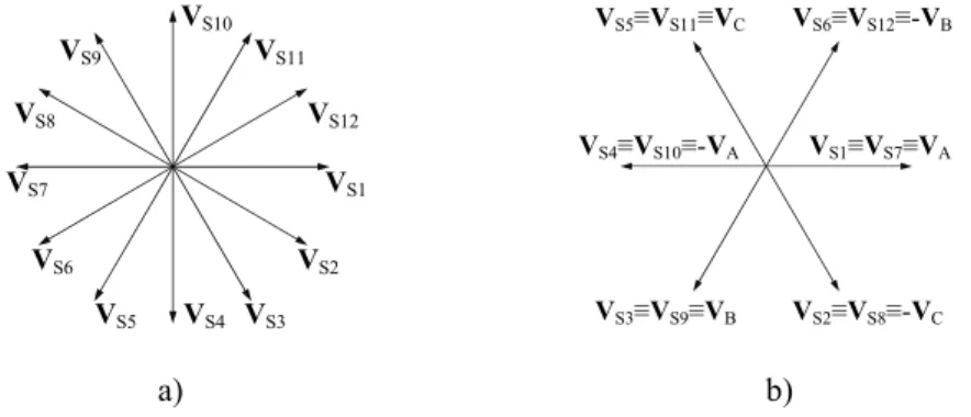
If we consider the winding with n=12 in Fig.1.1, the twelve stator polar windings can operate as an elementary dodeca-phase, bipolar winding system, when a twelve-phase voltage system is applied, Fig.1.2-a). Since q=1, then n/q=12 symmetric electric phases are needed. Another possible operating mode is as hexa-phase quadrupolar system, where n=12, q=2, n/q=6, thus a hexa-phase symmetrical voltage system is required, Fig.1.2-b).
VS10 VS9 VS11 VS8 VS12 VS7 VS1 VS6 VS2 VS5 VS4 VS3 VS5≡VS11≡VC VS6≡VS12≡-VB VS4≡VS10≡-VA VS1≡VS7≡VA VS3≡VS9≡VB VS2≡VS8≡-VC a) b)
Fig.1.2. a) Dodeca-phase voltage symmetrical system (n=12, q=1, n/q=12). b) Hexa-phase system (n=12, q=2, n/q=6).
Fig. 1.2-b) shows that a three-phase voltage system VA,VB,VC can operate as a hexa-phase system, by only reversing half of the polar windings; three-phase supplies can therefore easily provide this type of feeding, and so hexa-phase machine-operating mode is commonly preferred. This fact explains configurations in Fig.1.1, with the correspondent operating polar pairs practically used. Hexa-phase, 50Hz-fed systems can provide 3000rpm, 1500rpm, 1000rpm, 750rpm, etc. machine speeds by means of six, twelve, eighteen, twenty-four, etc. polar windings structures. Fig.1.3 shows an elementary machine with q = P = 2, n = 12, whereas Fig.1.4 shows all the possible windings arrangements.
S1 S2 S3 S4 S5 S8 S7 S6 S9 S10 S11 S12
Fig.1.3. Elementary machine with P = 2, n = 12. It has NS = 12 slots, one slot per-pole and per-phase, and
windings with non-reduced step (step = 3). Magnetic axes have been reported, with the conventional current orientation (cyclic-symmetric machine). The conventional current orientation for any polar belt is the same
as reported in Fig.1.4 a), b), c).
A B C 1 4 7 10 3 6 9 12 5 8 11 2 N a) A B C 1 7 3 9 5 11 4 10 6 12 8 2 N A B C 1 7 3 9 5 11 4 10 6 12 8 2 N b) c)
Fig.1.4. a) All-parallel connection; b) series-parallel connection; c) all-series connection for a four-pole, twelve polar belt, three phase winding.
1.1.3–ROTOR SQUIRREL CAGE
Fig.1.5 shows a squirrel-cage and the conventional loop currents, whereas Fig.1.6 shows a topologically equivalent circuit of the rotor cage electric structure.
iE iRk
iRk+1
iRk-1
Fig.1.5. A squirrel-cage is shown with conventional loop currents.
The inner loop in Fig.1.6 represents the frontal end-ring, and the outer loop is the opposite (back) ring; a rotor loop is determined by the area delimited by two contiguous bars and two opposite end-ring segments. The arrows mean that bar currents are directed toward the frontal end-end-ring; conventionally the orientation of all loop currents is counter-clockwise. The net end-ring current iE is normally zero for a healthy motor, and it is zero even in case of bar breakages; only a ring damage makes rise this current. As long as only broken bars will be considered, this current can be discarded from the model. This is a notable simplification, since the end-ring inductances are very hard to correctly evaluate.
iB3 iB2 iR3 iR4 iR2 iB4 iB1 iR(k-1) iE iR1 iB(k-1) iBm iRk iRm iR… iBk iB…
Fig.1.6. Topological-circuital scheme for the squirrel cage. Frontal end-ring is included in the total loop number, whereas back ring is redundant.
1.2 – ELECTRIC AND MAGNETIC EQUATIONS OF THE (n, m+1) MODEL 1.2.1–INTRODUCTION
The equations needed for establishing the motor electric circuit balance have been written by decomposing the electric system in a minimal-number of independent loops, and by associating to
each loop a loop-current ‘iu’ and a linked flux ‘ψu’ (according to the “right-hand” rule) as state variables (one intensive and the other extensive). Stated the followings definitions:
Ruk= mutual resistance between loops ‘u’ and ‘k’
Luk= mutual inductance between loops ‘u’ and ‘k’
χu= total resistive voltage drop on loop ‘u’’
u
dt
dψ = total inductive voltage drop on loop ‘u’
and named ‘vu’ the impressed voltage to the loop terminals, the Ohm’s and Faraday’s laws furnish, ∀u:
u u u
dt d
v =χ + ψ (1.2.1.1) or, by expanding the voltage drop terms:
=
∑
+∑
k ukk k uk k u dt L i d i R v . (1.2.1.2)Nel caso del motore oggetto di studio nella presente tesi, si hanno quattro matasse polari in parallelo per fase statorica a ciascuna dei quali è associabile una maglia, più le maglie in cui viene decomposta la gabbia rotorica, in numero di Nr + 1, essendo Nr il numero delle barre che
compongono la gabbia, come illustrato d’appresso. Il modello della macchina viene cosi ad essere caratterizzato da (12+Nr+1) equazioni, le quali comprendono anche l’equazione relativa ad uno dei
due anelli della gabbia. 1.2.2–STATOR EQUATIONS
About the stator circuits, we can refer from now on (and without loss of generality about the conclusions) to a parallel-connected phase structure as in Fig.1.4-a). This implies that all the n
polar windings are electrically independent (as they are seen from the voltage sources). For simplicity, the neutral connection is maintained, too (but the simulations and the direct measures that have been performed to validate the model presented insulated neutral). The n electric equations for the stator can be posed in matrix form as in (1.2.2.1).
[
( )
] [ ]
[ ]
( )
[
( )
t]
dt d t i R t vS = SS ⋅ S + ψS (1.2.2.1) where voltage, current, and linked flux column vectors are defined as follows:
( )
[
]
( )( )
( )
( )
( )
⎥⎥ ⎥ ⎥ ⎥ ⎥ ⎦ ⎤ ⎢ ⎢ ⎢ ⎢ ⎢ ⎢ ⎣ ⎡ = t v t v t v t v t v Sn S S S nx S ... 3 2 1 1 ;( )
[ ]
( )( )
( )
( )
( )
⎥⎥ ⎥ ⎥ ⎥ ⎥ ⎦ ⎤ ⎢ ⎢ ⎢ ⎢ ⎢ ⎢ ⎣ ⎡ = t i t i t i t i t i Sn S S S nx S ... 3 2 1 1 ;( )
[
]
( )( )
( )
( )
( )
⎥⎥ ⎥ ⎥ ⎥ ⎥ ⎦ ⎤ ⎢ ⎢ ⎢ ⎢ ⎢ ⎢ ⎣ ⎡ = t t t t t Sn S S S nx S ψ ψ ψ ψ ψ ... 3 2 1 1 ; (1.2.2.2)and where the resistance matrix is a diagonal one: