UNIVERSITÉ DE MONTRÉAL
AUTOMATIC DISASSEMBLY TASK SEQUENCE PLANNING OF AIRCRAFTS AT THEIR END-OF-LIFE
ARASH AFSHARZADEH
DÉPARTEMENT DE GÉNIE MÉCANIQUE ÉCOLE POLYTECHNIQUE DE MONTRÉAL
MÉMOIRE PRÉSENTÉ EN VUE DE L’OBTENTION DU DIPLÔME DE MAÎTRISE ÈS SCIENCES APPLIQUÉES
(GÉNIE MÉCANIQUE) JUILLET 2016
ÉCOLE POLYTECHNIQUE DE MONTRÉAL
Ce mémoire intitulé:
AUTOMATIC DISASSEMBLY TASK SEQUENCE PLANNING OF AIRCRAFTS AT THEIR END-OF-LIFE
présenté par : AFSHARZADEH Arash
en vue de l’obtention du diplôme de : Maîtrise ès sciences appliquées a été dûment accepté par le jury d’examen constitué de :
M. BALAZINSKI Marek, Docteur ès Sciences, président
M. MASCLE Christian, Doctorat, membre et directeur de recherche M. BAPTISTE Pierre, Doctorat, membre et codirecteur de recherche M. BARON Luc, Ph. D., membre
DEDICATION
To my dear Mom & Dad, To my dear brother and sisters, To my dear Nooshin
ACKNOWLEDGEMENTS
I would like to thank my director of research, Dr. Christian Mascle for accepting me in this project that provided me an opportunity to learn new interesting subjects and I am grateful of all of his supports and for all financial arrangements for this project.
I am also thankful of Dr. Pierre Baptiste for all of his time and interest in this work and for technically helping me in this project.
I also would like to thank Dr. Marek Balazinski for partially funding my research.
I would like to thank Dr. Baron Luc for taking the time to study this thesis and for his keen interest, questions and comments on this project.
I am thankful of all of the staff in mechanical engineering department for their help during my studies and my special thanks goes to Madams Martine, Carole and Myriam.
Finally, I would like to thank “Consortium de Recherche et d’innovation en Aérospatiale au Québec” (CRIAQ) and also industrial partners of CRIAQ ENV-412 project.
RÉSUMÉ
Une prise de conscience des problèmes environnementaux à l'échelle mondiale ainsi que des avantages économiques a stimulé les chercheurs à trouver les possibilités de réutiliser et de recycler les produits en fin de vie. Chaque année plusieurs centaines d'avions atteignent globalement fin de leur navigabilité et doivent être retirés du service actif. De ce fait, une attention accrue est maintenant accordée à la fin de vie des avions.
Désassemblage joue un rôle important dans la prise de décision de fin de vie. La faisabilité économique du processus de démontage avec beaucoup d'incertitudes est une préoccupation majeure limitant sa mise en œuvre dans la pratique de l'industrie. De nombreuses recherches dans le domaine de la planification et des opérations de processus de démontage a été fait, qui visent de plus en plus la faisabilité économique du démontage avec la réduction des temps de démontage de proposer des séquences de démontage optimisées. Par conséquent, ces dernières années, de nombreux chercheurs ont publié des articles sur la planification de la séquence de démontage des produits en fin de vie qui est un problème NP-complet optimisation combinatoire. Néanmoins, il y a eu un peu d'attention à la planification de la séquence de démontage d'avions en fin de vie. Cette thèse aborde la planification de séquence de démontage des pièces réutilisables d'avions en fin de vie avant le démantèlement pour le recyclage. Puisque les composants récupérés vont être utilisés à nouveau, une approche non-destructive tout en respectant les instructions fournies dans le manuel d'entretien d'avion intitulé « Aircraft Maintenance Manuel » (AMM) pour le retrait des pièces est prise en considération.
Ordonnancement de désassemblage dans cette recherche ne traite pas le séquençage le démontage des pièces comme dans d'autres études, mais il planifie séquence de tâches de démontage dans l'AMM. Une tâche de démontage consiste combinaison d'opérations pour la préparation du démontage ou le procède de démontage pour un ou plusieurs pièces.
Tout d'abord, un modèle de séquençage de démontage est proposé par l'examen structure des tâches de démontage dans l'AMM. Ensuite, un code Matlab est développé qui lit la base de données énuméré des tâches et sous-tâches qui sont acquises à partir de l'AMM et génère la séquence de démontage des tâches et sous-tâches automatiquement en utilisant le modèle proposé. Le code est capable de générer des séquences de désassemblage de tâches pour n’importe quelle pièce sollicitée.
Enfin, un algorithme glouton et un algorithme glouton adaptatif sont évalués pour optimiser la séquence de démontage des tâches afin de minimiser nombre de changements dans les zones d'opérations de démontage. Les résultats générés dans le code Matlab, suggère l'efficacité de l'algorithme glouton adaptatif proposé.
ABSTRACT
An awareness of the world’s environmental problems plus economic benefits has stimulated researchers to seek the opportunities to reuse and recycle end-of-life (EOL) products. Each year hundreds of aircraft globally reach end of their airworthiness and should be withdrawn from active service. Due to this fact, increased attention is now being paid to EOL of aircrafts.
Disassembly plays an important role in EOL decision making. The economic feasibility of the disassembly process with lots of uncertainties is a main concern limiting its implementation in industry practice. Many researches in the field of disassembly process planning and operations has been done that aim increasing economic feasibility of disassembly with reducing disassembly times with proposing optimized disassembly sequences. Consequently, in recent years, many scholars have published articles on disassembly sequence planning of EOL products that is a NP-complete combinatorial optimization problem. Nevertheless, there has been a scant attention towards disassembly sequence planning of EOL aircrafts.
This thesis addresses disassembly sequence planning of reusable components of EOL aircrafts before dismantling it for recycling. Since retrieved components are going to be used again, a non-destructive approach with respecting all instructions provided in aircraft maintenance manual (AMM) for removal of parts is taken into consideration.
Disassembly scheduling in this work does not deal with scheduling disassembly of components as in other works but it schedules sequence of removal Tasks in AMM. A removal task consists combination of operations for preparation of disassembly or process of disassembly for a part or multiple parts.
At first, a disassembly sequencing model with considering structure of disassembly tasks in AMM is proposed. Afterwards a Matlab code is developed which reads from enumerated database of tasks and subtasks that are acquired from AMM and generates disassembly sequence of tasks and subtasks automatically using the proposed model. The code is capable of generating disassembly sequences of tasks for any given removal task of solicited part.
Finally, a greedy and an adaptive greedy algorithm are proposed to optimize disassembly sequence of tasks with minimizing changes in visited zones of disassembly operations. Results generated in Matlab code, suggests effectiveness of proposed adaptive greedy algorithm.
TABLE OF CONTENTS
DEDICATION ... III ACKNOWLEDGEMENTS ... IV RÉSUMÉ ... V ABSTRACT ...VII LIST OF TABLES ... XI LIST OF FIGURES ...XII LIST OF SYMBOLS AND ABBREVIATIONS... XIVCHAPTER 1 INTRODUCTION ... 1
1.1 Problem statement ... 1
1.2 Literature review ... 3
1.2.1 Disassembly sequencing ... 3
1.2.2 Aircraft at its end-of-life ... 13
1.2.3 Disassembly sequence planning for aircrafts ... 15
1.2.4 Conclusion of literature review ... 16
1.3 Objective ... 18
1.4 Thesis structure ... 19
CHAPTER 2 METHODOLOGY ... 20
2.1 Studying of previous works ... 20
2.2 Developing new model ... 20
2.3 Validation of the model ... 20
2.4 Finding an optimized disassembly sequence ... 21
2.5 Automatic generation of sequences of disassembly ... 21
3.1 Principles ... 23
3.1.1 TASK numbering in AMM ... 23
3.1.2 AMM structure ... 24
3.2 Disassembly model in the previous work ... 28
3.2.1 Methodology ... 28
3.2.2 Problems with Camelot’s model: ... 30
3.2.3 Conclusion ... 31
3.3 Developing a model for disassembly sequencing ... 32
3.3.1 Establishing a graph for disassembly of one part ... 32
3.3.2 Establishing a graph for disassembly of multiple parts ... 35
3.3.3 Mathematical model of a disassembly graph ... 38
3.4 Automatic generation of disassembly sequences ... 38
3.4.1 Data acquisition from AMM ... 38
3.4.2 Automatic generation of disassembly sequences ... 39
3.4.3 Validation of model ... 43
CHAPTER 4 DISASSEMBLY OPTIMIZATION ... 49
4.1 Introduction ... 49
4.2 Graph theory ... 52
4.3 Heuristic methods ... 54
4.3.1 Greedy algorithm ... 54
4.3.2 Adaptive greedy algorithm ... 58
4.3.3 Comparison of results ... 65
CHAPTER 5 CONCLUSION AND RECOMMENDATIONS ... 67
5.2 Recommendations for future works ... 67 BIBLIOGRAPHY ... 69
LIST OF TABLES
Table 1-1: PAMELA 3D approach ... 14 Table 1-2: Disassembly sequencing ... 17 Table 4-1: Comparison of zone changes ... 66
LIST OF FIGURES
Figure 3-1: An example of maintenance task in AMM ... 24
Figure 3-2: Structure of a TASK in AMM ... 26
Figure 3-3: Sequence of implementing tasks in AMM ... 27
Figure 3-4: An example of a task with referral to other tasks ... 27
Figure 3-5: An example of disassembly graph model developed by Camelot ... 29
Figure 3-6: Edge between two tasks ... 30
Figure 3-7 Camelot’s disassembly graph for an actual task of CRJ 100/200 AMM ... 32
Figure 3-8: Example of a Task with four subtasks ... 33
Figure 3-9: Subtasks referring to other tasks ... 33
Figure 3-10: Graph of tasks for implementing ‘Task’ ... 34
Figure 3-11: Disassembly graph for two tasks for removal of two parts ... 36
Figure 3-12: Connecting two graphs at the common tasks ... 36
Figure 3-13: Connecting two graphs with consecutive common tasks ... 37
Figure 3-14: Connecting multiple graphs at the common tasks ... 37
Figure 3-15: Forming adjacency matrix of a Graph ... 38
Figure 3-16: Structure of data generated from AMM ... 39
Figure 3-17: Iterative procedure of retrieving subtasks ... 41
Figure 3-18: Procedure of establishing disassembly sequences for a Task ... 42
Figure 4-1: Possible sequences for a directed precedence graph ... 49
Figure 4-2: Assigning zones to disassembly tasks in disassembly model ... 51
Figure 4-3: (a) Disassembly graph as separate chains (b) Forming of loops after integration of disassembly chains into one graph ... 53
Figure 4-5: Update of Disassembly Graph at third iteration ... 57
Figure 4-6: Update of Disassembly Graph at fourth iteration ... 61
Figure 4-7: Update of Disassembly Graph at fifth iteration ... 62
Figure 4-8: Update of Disassembly Graph at sixth iteration ... 63
Figure 4-9: Update of Disassembly Graph at seventh iteration ... 64
LIST OF SYMBOLS AND ABBREVIATIONS
2D Two-Dimensional
3D Three-Dimensional
AFRA Aircraft Fleet Recycling Association AMM Aircraft Maintenance Manual
AMTOSS Aircraft Maintenance Task Oriented Support System ASGAs Algorithm of Self-Guided Ants
ASPEN Assembly Sequence Planning and Evaluation System ATA Air Transport Association
BOM Bill Of Material CAD Computer Aid Design CO Close Out
CRIAQ Consortium de Recherche et d'Innovation en Aérospatiale au Québec DFD Design For Disassembly
DFIG Disassembly Feasibility Information Graph DPN Disassembly Petri Net
DPP Disassembly Process Plans DSP Disassembly Sequence Planning EASA European Aviation Safety Agency EOL End Of Life
FDOM Fuzzy Disassembly Optimization Model GA Genetic Algorithm
GRASP Greedy Randomized Adaptive Search Procedure HBN Hybrid Bayesian Network
JSU Job Set-Up
JSUI Job Set-Up Information MTM Methods Time Measurement NP Non-deterministic Polynomial-time OEM Original Equipment Manufacturer P Procedure
PAMELA Process For Advanced Management Of End-Of-Life Aircraft
PN Perti Net
PPX Precedence Preservative Crossover PSO Particle Swarm Optimization RFID Radio-Frequency Identification TS Topological Sort
CHAPTER 1
INTRODUCTION
1.1
Problem statement
Technically life of an airplane is close to indefinite. As long as aircraft is serviced and there are spare parts available, an aircraft can be kept airworthy. The business life of an aircraft, however, is limited. Maintenance costs will increase when an aircraft becomes older and bear in mind that new aircraft with newer technology has higher passenger comfort and lower utilization cost, such as fuel and maintenance cost. When an aircraft has reached the end of its business life, it will be retired and withdrawn from service. Over the next 20 years, it is estimated that approximately 12000 airplanes, which are currently in service for different purposes, will reach their End of Life (EOL) (Asmatulu et al., 2013). Consequently, this question raises that what we can do with hundreds of aircrafts arriving at the end of life. Stock them in deserts or crush them to recycle materials. There are several alternatives, but original equipment manufacturers (OEMs) are also attentive that any alternatives, as a global analysis, should consider different criteria of sustainable development. Upon reaching the end of aircraft airworthiness, the airline/owner decides what to with the aircraft. From environment and economic point of view abandonment or unlimited duration stock of airplanes are not wise choices. Therefore, the owner may decide to perform a reconversion activity (commercial to freight for example) or sell the retired aircraft for being disassembled (The process comprising all the activities required to remove all the valuable components from an aircraft, which can be re-used in another aircraft), dismantled (The process comprising all the activities required to make it possible to recycle materials from an aircraft) and subjected to a recovery of its materials for recycling.
As it was explained, we understand that it is a significant need to recycle materials or re-use parts and equipment of dismissed aircrafts that are still in a good state of functioning. In this context, the Project CRIAQ ENV412 was defined to allow university researchers to study on sustainable development and end of life of aircrafts. Current thesis will only discuss retrieving of selective and non-destructive disassembly of high value parts, which are considered reusable.
For the re-use/resale of retrieved items and new assemblies as previously used parts, the disassembly of aircraft parts is subject to following best practices (AFRA, 2013). Furthermore,
reusability of removed parts and equipment is conditional upon meeting all required maintenance procedures. The procedure of disassembling parts is quite same as if the aircrafts parts were in phase of maintenance, thus the operators should respect procedures in Aircraft Maintenance Manual (AMM).
In this study, we do not have access to design data, 2D or 3D drawing of parts or general assemblies of airplane. Therefore we do not have distances between parts or precedence relationships among them. Also we do not have a database that provides costs of disassembly operations, the tools utilized and man-hour estimates of activities. The only document which is handed over to us is the AMM in the PDF format files which a computer code reads these files as texts and retrieves enumerated tasks. In the AMM, duration of disassembly tasks is not provided but order of execution of procedures for each of tasks is written in there. Each of tasks in AMM has a task number and is enumerated in accordance with ATA standard.
Since an airplane is a large product, during disassembly of reusable parts at EOL stage, different areas of disassembly operations will be existed. Therefore, disassembly tasks are dispersed in different zones of airplane. In some cases of part removals, platforms, technicians with specified skills and training or special equipment is needed. The disassembly operations are labour intensive and disassembly project manager needs to plan for different teams of technicians and acquisition of equipment. With considering a lean approach, which eliminates waste from process, we do not like to change our working zone as much as possible. Therefore, we are interested in an approach to minimize changing working zones and displacements of labor and equipment consequently. The target is generating an optimized disassembly sequencing plan for retrieving reusable parts of an aircraft its EOL. The optimization factor is total number of zones changed in a disassembly project.
The AMM is more than 3000 pages with more than 45000 tasks. This requires power of a computer software to aid automatic data acquisition from AMM and to generate disassembly task sequencing and applying optimization algorithms. For this reason a Matlab code is developed.
1.2
Literature review
1.2.1
Disassembly sequencing
Disassembly for recovery is defined as the systematic extraction of valuable parts of an outdated product with goal of re-using or recycling extracted parts. Disassembly as a process was performed in the slaughterhouses more than a century ago. However, the “systematic approach” of disassembly has relatively a short history of 30 years.
Disassembly is an important process in retrieving some value of outdated products since it allows for the selective retract of desired parts. In the literature, because of this benefit many studies has been done in the area of disassembly.
In other hand, many papers focus on disassembly for the purposes of maintenance and repair, particularly if these had to be performed in environments such as space stations, nuclear power plants, etc. with harsh or hard to access environments. In these cases, the design should foresee and allow for automated or remote disassembly and reassembly.
Lambert (2003) categorizes a variety of purposes of works on disassembly sequences as following: - Remote construction and repair in inaccessible or hazardous environments such as in
spacecraft and nuclear equipment. - Optimal repair and maintenance. - A tool for assembly optimization.
- Design and optimization of disassembly lines.
- Optimum product design regarding the product’s end-of-life phase, which is called Design for Disassembly (DFD).
Disassembly sequencing is about the problem of finding the best order of disassembly tasks in the retrieving of different parts of a product. Disassembling of complex products requires mathematical modelling and a connection representation aimed at selecting a good or optimum sequence of disassembly tasks. To find the best or optimum path, in most cases heuristics, metaheuristics or mathematical programming is applied on the model.
In the literature on disassembly sequencing, two basic approaches can be recognised: (a) the mechanical approach that is mainly used in the analysis of mechanical assemblies, and (b) the hierarchical tree approach that is mainly applied to electrical and electronic equipment. The mechanical approach originates from the assembly study, and the hierarchical tree approach is related to the Bill of Materials, which is applied in Materials Resource Planning.
Disassembly is considered to be as the reverse process of assembly method by many disassembly researchers and then, most authors in disassembly area have researched in assembly area. Takeyama et al. (1983) said, “The sequence of assembly is the reverse of that of disassembly”. Lambert (2003) summarized essential differences between assembly and disassembly as following:
- Disassembly is usually not performed to its full extent: incomplete disassembly is often preferred, which adds the disassembly depth to the decision variables.
- The assembly process is often not completely reversible (decisions need to be made between destructive and non-destructive disassembly).
- The value added in disassembly processes is usually modest compared to that obtained in assembly.
- Uncertainty exists with regard to the quality of the components,
- Uncertainty exists in the supply of discarded products from both qualitative and quantitative points of view,
- In disassembly, a variety in supplied products might be present.
- Due to mentioned features, disassembly is mainly carried out by human labour instead of by automated assembly lines and robots.
Bourjault (1984) did the first attempt and formulated assembly sequencing problem using a systematic approach in his doctoral thesis. He presented automatic generation of assembly sequences of a product with using rules by answering a series of “yes” or “no” questions about mating of parts for an assembly and modeled a product by utilizing the information contained in a BOM and an assembly drawing to form a liaison graph, where the components are the nodes and
the liaisons are the arcs representing the mates. An Algorithm determined assembly sequences using the liaison graphs.
De Fazio and Whitney (1987) proposed simplified set of rules, “precedence constraints”, by asking two questions about liaison precedence. Questions ask about “what liaisons must be done prior to doing liaison i” and “what liaisons must be left to be done after doing liaison i”.
Khosla and Mattikali (1989) developed a methodology that uses software to automatically generate assembly sequences from a 3D model of the assembly.
Baldwin et al. (1991) also utilized CAD for automatic assembly sequence generation.
Kanai et al. (1996) developed a computer aided Assembly Sequence Planning and Evaluation system (ASPEN) that takes all the solid model components of a product and automatically determines all feasible sequences by decomposition. ASPEN also determines the optimum sequence using Methods Time Measurement (MTM) as time standards for operating time determination.
Zhang and Kuo (1997) proposed a graph-based approach to find feasible disassembly sequences from the CAD system directly and automatically.
Gungor and Gupta (1997) developed a methodology to evaluate different disassembly strategies to choose the best among them. They also proposed a disassembly sequence generation heuristic, which gives a near optimum disassembly sequence.
Moore et al. (1998) proposed an algorithm which automatically generates a disassembly Petri net (DPN) from a geometrically-based precedence matrix. They analyzed the resulting DPN to generate all feasible disassembly process plans (DPPs), and cost functions were utilized to determine the optimal DPP.
O'Shea et al. (1998) provided the state of the art different issues particular related to disassembly planning. The subjects covered issues from product representation, to task analysis, task representation, sequencing, clustering, life cycle engineering issues, and cost estimation. Materials data requirement issues and some practical applications in disassembly plant.
Gungor and Gupta (1998) discussed the uncertainties and its sources in disassembly sequence planning (DSP) and presented a methodology to deal with uncertainty in DSP implementation for products with defective parts.
Srinivasan and Gadh (2000) analysed the problem of removing one or more components of an assembly, defined as selective disassembly, and presented geometric abstractions and representations for automated selective disassembly analysis of geometric models.
Hsin-Hao et al. (2000) developed the economic analysis method of the disassembly process and develop an artificial neural network approach for disassembly sequence generation problem. Due to combinatorial nature of disassembly sequencing problem, there is an increasing trend in the use of metaheuristics.
Lazzerini and Marcelloni (2000) presented a Genetic Algorithm (GA) for generating optimal assembly sequences. Population generation randomly generated usually non-feasible sequences, however they defined crossover and mutation operators to allow the GA to evolve to feasible optimal sequences. The algorithm were applied to sequences consisted of up to 17 components. Kuo (2000) addressed the disassembly sequence and cost analysis for the electromechanical products during the design stage. He divided disassembly planning into four stages: geometric assembly representation, cut-vertex search analysis, disassembly precedence matrix analysis, and disassembly sequences and plan generation. The disassembly cost is categorized into three types: target disassembly, full disassembly, and optimal disassembly.
Seo et al. (2001) presented a genetic algorithms based heuristic approach for an optimal disassembly sequence considering economic and environmental aspects.
Murayama et al. (2001) presented a methodology of generating disassembly sequences for component replacement at maintenance stages using information entropy evaluation and heuristics for efficient generation of disassembly sequences. They evaluated disassembly based on two criteria: disassembly time and disassemblability.
Erdos et al. (2001) investigated the modelling and evaluating product end-of-life options that is the problem of representing products and finding disassembly sequences with the goal of maximizing revenue. They developed algorithms to generate the product recovery graph, to find optimal disassembly plans that maximize revenue using the generated product recovery graph with uncertainties of the end-of-life products.
Gungor and Gupta (2001) presented a systematic approach to generate an optimum disassembly sequence plan for product recovery. They generated a disassembly precedence relationships matrix
representing the geometric precedence information using CAD representation of the product. Afterwards, they utilized a branch-and-bound heuristic to find an optimum disassembly sequence. Tang et al. (2002) surveyed the state of art in disassembly modelling, planning and its application. Rai et al. (2002) presented a disassembly sequence generation methodology using the Petri net technique by correlating cost indices combined with heuristic search procedures. The presented heuristic generates and searches a partial reachability graph to arrive at an optimal or near-optimal disassembly sequence based on the firing sequence of transitions of the Petri net model.
Lambert (2003) surveyed the literature on disassembly sequencing and summarised and categorised work of more than 200 articles in the area of disassembly sequencing.
Torres et al. (2003) presented an algorithm based on a representation method for products, which shows the hierarchical relationships among components of the product. They established an algorithm for partial non-destructive disassembly sequence of a product. The disassembly sequence were obtained automatically from design CAD data.
Mascle and Balasoiu (2003) addressed a wave propagation based disassembly algorithm to select the disassembly sequence of a specific component of a product.
Lambert (2005) presented the search for optimum disassembly sequences for products that can be represented by disassembly precedence graphs and that are subjected to sequence-dependent disassembly costs. He applied an exact approach, based on iteratively solving a binary linear programming.
Li et al. (2005) presented an object-oriented intelligent disassembly sequence planner for maintenance based on the disassembly constraint graph using genetic algorithms to generate near optimal disassembly sequence from all the feasible combination of the disassembly operations. Lambert and Gupta (2005) in their book reviewed disassembly related issues and presented comprehensive details about methods, approaches, and applications in this field.
Dong et al. (2006) presented an approach to automatic generation of disassembly sequence from hierarchical attributed liaison graph of an assembly through recursively decomposing the assembly into subassemblies. Their approach integrates general geometric reasoning with the knowledge about how to generate feasible and practical disassembly sequences.
Chung and Peng (2006) presented an evolutionary algorithms approach to generate a feasible and optimal plan for selective disassembly in remanufacturing, ensuring both batch disassembly of components and tool accessibility to fasteners.
Kongar and Gupta (2006) addressed a genetic algorithm for disassembly sequencing of EOL products.
Sarin et al. (2006) developed a disassembly optimization problem as precedence constrained asymmetric traveling salesman problem and developed an iterative procedure to minimize the costs associated with the disassembly process while maximizing the benefits resulting from the recovery of components and subassemblies that constitute the product.
Kang and Xirouchakis (2006) surveyed the disassembly sequencing problems in which second-hand or EOL products are disassembled into basic parts and components, especially due to repair and maintenance.
Langella (2007) presented heuristic algorithm with considering demand for disassembled part for remanufacturing of products.
Shimizu et al. (2007) applied genetic algorithms to address a system supporting strategic decision-making on disassembly for recycling at the design stage of the product life cycle. The issue of uncertainty modelling and management arises in the context of the optimal disassembly planning problem, one of the problems to be addressed by remanufacturing processes.
Reveliotis (2007) addressed a reinforcement learning approach for providing optimal solutions to the optimal disassembly problem considering uncertainties.
Kim et al. (2007) provided a literature review on works done in disassembly scheduling area. Giudice and Fargione (2007) presented a genetic algorithm approach to disassembly process planning that supports the search for the disassembly sequence best suited for both aspects, service of the product and recovery at the end of its useful life.
Dong et al. (2007) offered an approach based on accessibility and EOL strategy, using Petri net modelling to generate an optimal disassembly sequence. Their approach utilize AND/OR graphs to generate all feasible disassembly sequences, and then graphs are transferred into Petri net graphs while accessibility values and life span values of components are taken into consideration to obtain the optimal disassembly sequence.
Duta et al. (2008) developed an evolutionary algorithms approach for the multi-criteria optimization problem of the disassembly scheduling.
Lambert and Gupta (2008) presented a heuristic algorithm for disassembly sequencing problems subjected to sequence dependent disassembly costs using disassembly precedence graph of a cell phone with twenty-five parts.
Wang et al. (2008) presented a GA method to solve disassembly sequence planning problem. To describe product disassembly sequence and operation information, they presented disassembly feasibility information graph (DFIG). Then, disassembly sequence planning problem is mapped onto the DFIG as an optimal path-searching problem. In GA a chromosome represents the sequence of disassembly operations, and they applied the precedence preservative crossover (PPX) as crossover operator for establishing next generation of chromosomes. The generated chromosomes which does not respect precedence relations are rejected.
Adenso-Díaz et al. (2008) claimed since determining an optimal disassembly sequence planning is NP-complete and complex as well as a challenging problem to solve, heuristic and metaheuristic techniques may be the only practical ways to solve such problems. They considered two criteria to look for: First, a sequence that its cost is close to their cost aspiration. Second, a sequence that prioritizes some selected parts to be disassembled as early as possible. In their article they presented a greedy randomized adaptive search procedure (GRASP) and path-relinking-based heuristic methodology to solve this bi-criteria disassembly planning problem. The proposed algorithm were applied to four different products with a maximum of 100 components in each.
Tripathi et al. (2009) proposed a metaheuristic named Algorithm of Self-Guided Ants (ASGAs) to solve the computationally hard fuzzy disassembly optimization model (FDOM) problem. Their algorithm aims to maximize the net revenue generated from disassembled components from an EOL product. The factors considered for their model are number of parts, number of subassemblies, number of joints, setup costs, joint breaking costs, recovery value and disposal costs.
Grochowski and Tang (2009) presented a machine learning approach based on a DPN and a hybrid Bayesian network (HBN) to model the disassembly process and predict the outcome of each disassembly action by examining the probabilistic relationships between the different aspects of the disassembly process.
Puente et al. (2010) presented an algorithm to sequence tasks to be performed in the disassembly of a specific material from a product or to separate all the materials of a product. They utilized hierarchical model of a product with having disassembly time of components.
Yun and Moon (2011) proposed a GA approach with utilizing a topological sort (TS) based procedure for solving precedence constrained sequencing problems. The TS-based procedure used in the proposed GA approach can generate feasible sequences in precedence constrained sequencing problems. The proposed algorithm is applied to a problem with a maximum of seventy-five nodes.
ElSayed et al. (2011) developed an automated disassembly cell for online (real time) partial disassembly operations of PCs at their EOL. Their cell consists a robotic arm, a camera, range-sensing and component segmentation visual algorithms. The authors applied an online GA approach for finding near/optimal disassembly sequencing. The precedence preservative crossover (PPX) methodology was utilized for the crossover operation. The fitness value was obtained by the overall disassembly time.
Go et al. (2011) reviewed several disassembly methods to enhance the recovery of EOL products, especially for vehicles, so that valuable parts are efficiently retrieved
Liu et al. (2012) applied an improved max–min ant system based algorithm to generate a near-optimal solution for the problem of product disassembly sequence planning in a virtual maintenance environment with considering all disassembly constraint information, such as adjacency and constraint relations between parts and subassemblies, disassemble time, disassemble tool, disassemble priority, quality, reliability and load of disassemble machine, etc
Smith et al. (2012) introduced an approach for creating, and searching methods of disassembly sequence structure graph model for multiple-target selective disassembly sequence planning. The approach uses expert rules to choose parts, part order, and part disassembly directions, based on contact, motion, and fastener constraints.
Go et al. (2012) utilized a GA approach implemented in Matlab in order to determine the optimal disassembly sequence of an engine of an EOL vehicle. The applied method achieves the minimum disassembly time with considering precedence relationships.
Wan and Gonnuru (2013) proposed the use of radio-frequency identification (RFID) technology to support disassembly decisions for end-of-life products. They presented a fuzzy-based disassembly
planning and a disassembly sequencing model to maximize net profit and utilized GA approach for finding an optimal solution.
Tian et al. (2013) presented chance constrained programming models based on the uncertainty feature of a disassembly process. In their model removal times, labour costs and disassembly direction changes is taken into consideration. Authors proposed two hybrid intelligent algorithms to solve the proposed models: one integrating stochastic simulation and neural network, and another integrating stochastic simulation, genetic algorithm and neural network.
Popescu and Iacob (2013) proposed a disassembly method based on two elements: The connection interface concept and the mobility operator that integrates information on geometrical constraints, contact surface relative position and common area, neighboring components, and relative mobilities of the assembly components from the 3D CAD model of a product. Heuristic rules and unit ball concept for determining component mobility is utilized.
Wang et al. (2013) reviewed the fundamental methodology and its development of computerized intelligent disassembly planning research. It is concluded that heuristic algorithms are increasingly being used to search for the optimal solution to improve efficiency. However due to complexity of the matter for more accurate results there is a demand to integrate intelligent methods such as genetics algorithm or artificial networks. They also argue that disassembly planning is essentially a process that needs person’s knowledge and experience of engineering, so solely a perfect mathematical optimization theory is not a way to the final resolution.
Zhao et al. (2014) presented a reasoning algorithm using a Fuzzy reasoning PN for optimisation of a disassembly process based on the maximal reclaiming profit of retrieved parts.
Rickli and Cameliob (2014) investigated impact of EOL product quality variability, represented as an EOL product age distribution, on the optimal or near-optimal partial disassembly sequence. Moreover, they utilized a GA heuristic based on sequence feasibility, expected profit standard deviation and profit probability per EOL product.
Xia et al. (2014) proposed a simplified Teaching–Learning-Based Optimization algorithm for solving disassembly sequence planning problems. The algorithm utilizes population-based evolutional method and consists of three parts: a Feasible Solution Generator to generate a feasible disassembly sequence, a Teaching Phase Operator and a Learning Phase Operator used to learn
and evolve the solutions towards better ones by applying crossover operation that preserves precedence relationships.
Giri and Kanthababua (2015) proposed a method to generate the disassembly sequences for mechanical products, which uses the part interference matrix that contains the removal directions of the parts and the part connection graph that indicates the contact among the parts in the assembly. For generating the part connection graph, 2D views generated from the CAD assembly model for automatically identifying the part removal directions is utilized. They applied a heuristic method to generate the best feasible disassembly sequences.
Issaoui et al. (2015) presented a solution space reduction for disassembly sequencing problems. Connection tree of a target component is constructed with using its CAD model. The generation of sequences is based on reading of connection tree branches and elimination of infeasible ones. They applied their method to a product with 22 components.
Riggs et al. (2015) presented a two-stage optimization algorithm that first determines the optimal partial disassembly sequence according to reuse value of components, and in next stage adds sequence dependence task times and finds the optimal partial disassembly sequences.
Berg et al. (2015) presented an application of immersive computing technologies to aid in evaluating disassembly sequences in early design. The application displays both 3D geometry of a product and an interactive graph visualization of existing disassembly sequences. For presented work, authors generated the disassembly graphs manually. The calculated optimal path can be highlighted allowing the user to compare the optimal sequence against alternatives.
Mitrouchev et al. (2015) presented a method based on the lowest levels of a disassembly product graph instead of considering the geometric constraints for each pair of components. It is discussed that if the product has a modular design, this will allow aggregating some parts of the assembly in modules and reaching the target without dismantling the components one by one. The proposed method first generates disassembly geometry contacting graph of the product and then generates the feasible disassembly sequences. Moreover, authors proposed concept of micro-units that eliminates all the components that are unrelated to the target ones, permitting reducing the number of iterations for disassembly sequence generation and consequently reducing the search time.
Wang et al. (2016) introduced a method for evaluation of disassembly operations in Virtual Environment. A set of five criteria is proposed: visibility of the sub-assembly part, disassembly angles, stability of the subassembly, number of tools’ changes and path direction change. The presented method can be used for disassembly sequence generation either at early stage of design or at EOL.
Alshibli et al. (2016) presented a metaheuristic algorithm for disassembly sequencing, with using a sensory system and an online real-time Tabu search applied to a robotic arm that executes disassembly operations. The objectives of the proposed algorithm are to minimize the traveled distance by the roboticarm, the number of disassembly method changes, and the number of robotic arm travels by combining the identical-material components together. The authors state that the applied Tabu search runs faster than GA approach for the similar problem.
1.2.2
Aircraft at its end-of-life
Until a few years ago, EOL aircrafts were abandoned. Starting in the 2000s, the two largest aircraft manufacturers Airbus and Boeing began to get interested in the management of aircrafts to develop alternative approaches of how to handle aircrafts at their EOL. Airbus launched the PAMELA project (Process for Advanced Management of End-of-Life Aircraft), as an aircraft dismantling demonstration project with support from the European Commission's "LIFE" initiative under the classification of "waste management, recycling and reduction of landfill".
The main concept was implementing strategies to develop a set of best practices, and standards, for the dismantling of an aircraft safely and with respect for the environment.
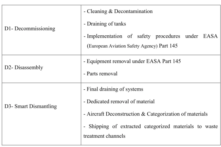
During the PAMELA project (Airbus, 2008), the consortium created a three-stage process approach of handling EOL aircraft, called 3D approach. Table 1-1: Table 1-1 shows summary of this 3D approach.
Table 1-1: PAMELA 3D approach
D1- Decommissioning
-Cleaning & Decontamination -Draining of tanks
-Implementation of safety procedures under EASA
(European Aviation Safety Agency) Part 145
D2- Disassembly - Equipment removal under EASA Part 145 - Parts removal
D3- Smart Dismantling
- Final draining of systems - Dedicated removal of material
- Aircraft Deconstruction & Categorization of materials - Shipping of extracted categorized materials to waste treatment channels
In other hand, in 2006 eleven charter companies established AFRA (Aircraft Fleet Recycling Association) with the goal to organize and present an industry perspective on aircraft sustainability through the development and recommendation of best practices and technologies for the management of the world’s older fleet.
The AFRA has published “Best Management Practice for Management of Used Aircraft Parts and Assemblies and for Recycling of Aircraft Materials” (BMP). BMP is a document that represents a collection of recommendations concerning best practices for the management of parts that are removed from an aircraft at its EOL.
- The disassembly: intended to guide aspects of the management of parts removed from an EOL aircraft.
- The recycling: intended to guide aspects of the processing of aerospace materials in order to transform these into usable materials.
Law does not enforce AFRA’s procedures and guidelines. However, AFRA provides accreditation to companies in the field of dismantling and disassembling aircraft parts. It gives confidence to clients who want to use the spare parts, which are retrieved from EOL aircrafts that they will use the parts that are in good state and all the best practices has been considered at the time of retrieval from airplanes.
Another important study in this context is a major research project named CRIAQ ENV-412 that is an initiative of the “Consortium de recherche et d'innovation en aérospatiale au Québec” (CRIAQ) and funded by Natural Sciences and Engineering Research Council (NSERC) and partners Bombardier Aerospace, Bell Helicopter Textron Inc., Aluminerie Alouette, BFI Canada, Sotrem-Maltech, CRIAQ, Nano Québec and Mitacs with collaboration of École Polytechnique de Montréal, Centre technologique en aérospatiale (CTA), Université Laval, École de technologie supérieure (ETS) and McGill University.
1.2.3
Disassembly sequence planning for aircrafts
Even though the literature is abound with disassembly sequencing, except the works done in context of CRIAQ-ENV412 project, one cannot find studies specifically dealing with issue of disassembly sequence planning of aircraft re-usable part at EOL of aircraft.
There is just a very few studies concerning disassembly of parts, which is for the purpose of maintenance of aircraft parts.
Cheung et al. (2005) and Cho et al. (2009) discussed staff rostering to facilitate the allocation of labor resources at the time of aircraft maintenances.
Christiand and Yoon (2007) proposed a GA approach for determining an optimal assembly/disassembly path planning for maintenance of aircraft parts. Constraints such as obstacles and the part distances was taken into consideration.
Zhang et al. (2008) presented a component disassembly approach for aircraft assembly process based on fuzzy-clustering algorithm.
Hassan and Yoon, (2010) presented a disassembly path planning algorithm for maintenance of aircraft parts considering geometry constraints with the purpose of optimizing time of disassembly.
Zhong et al. (2011) proposed metaheuristic methods for maintenance of large equipment parts including aircrafts. They presented a Dijkstra’s algorithm and particle swarm optimization (PSO) to determine optimal disassembly sequences. The proposed method was applied to disassembly sequences for maintenance of a nose landing gear system of a regional jet with ten components to be disassembled. The authors state that their proposed method reduce the calculation complexity, and it is faster than a GA approach.
1.2.4
Conclusion of literature review
As presented in previous section study of disassembly sequencing has started about thirty years ago and has attracted many scholars. However, apparently researchers are not done with this issue due to its complexities. Many improvements has taken place but limits are still there. Each disassembly case and its constraints is different with another one and a solution that best fits that specified problem should be determined.
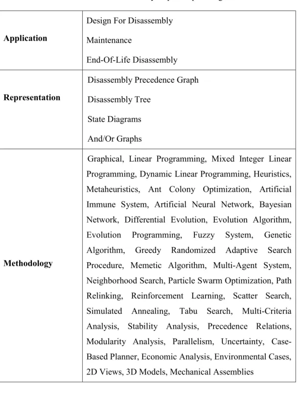
Table 1-2 summarizes disassembly sequencing problems into three categories: applications, representations and methodologies. As it can be seen from methodology section, there are quite considerable number of techniques that are used for determination of optimal disassembly sequences. Nevertheless, seems that publication with utilizing genetic algorithm approach are more than other approaches. However, this method also has its own limits and that is why scholars are still seeking other methods.
The state-of-the-art about the disassembly sequence planning of aircrafts shows that there is just a couple of studies with the application of maintenance of aircrafts and there is a big gap in literature in this subject. Actually, the only related work towards disassembly sequence planning of EOL aircraft parts has been initiated in CRIAQ-ENV412 and Camelot (2012) has addressed this subject in her master studies.
Current work presented in this thesis was defined as continue of Camelot’s study with the purpose of checking and validation of her model and algorithm, and to automatically generate disassembly sequences in case of verification/modification of proposed model. Therefore, Camelot’s approach is investigated thoroughly and details will be presented in next chapters.
Table 1-2: Disassembly sequence planning
Application
Design For Disassembly Maintenance
End-Of-Life Disassembly
Representation
Disassembly Precedence Graph Disassembly Tree
State Diagrams And/Or Graphs
Methodology
Graphical, Linear Programming, Mixed Integer Linear Programming, Dynamic Linear Programming, Heuristics, Metaheuristics, Ant Colony Optimization, Artificial Immune System, Artificial Neural Network, Bayesian Network, Differential Evolution, Evolution Algorithm, Evolution Programming, Fuzzy System, Genetic Algorithm, Greedy Randomized Adaptive Search Procedure, Memetic Algorithm, Multi-Agent System, Neighborhood Search, Particle Swarm Optimization, Path Relinking, Reinforcement Learning, Scatter Search, Simulated Annealing, Tabu Search, Multi-Criteria Analysis, Stability Analysis, Precedence Relations, Modularity Analysis, Parallelism, Uncertainty, Case-Based Planner, Economic Analysis, Environmental Cases, 2D Views, 3D Models, Mechanical Assemblies
1.3
Objective
In this study, target is to have an optimized disassembly sequence of reusable parts of an aircraft in its end-of-life, leading to an automatic generation of a disassembly process with respecting maintenance procedures.
In literature review, many different approaches for optimizing a disassembly sequencing were explained. Obviously when talking about optimizing, there should be a parameter to optimize. The main parameters which was consider in researches is reducing time and costs. For this most of studies offered had considered times of disassembly tasks for all operations or costs of any disassembly action or equipment utilized and with applying their proposed optimization algorithm could find an optimized disassembly sequence.
However, for our study, we do not have any of such databases. The only resource that is available is the Aircraft Maintenance Manual. Hopefully since tasks in AMM is standardized by ATA for all type of airplane, (no matter who the OEM is), we have access to ATA chapter of is each task which is part of task’s name in the AMM. Consequently, we can understand the task is performed in which zone of the aircraft.
Since an airplane is a large product, during disassembly or reusable parts at EOL stage, different areas of work will be existed. Therefore, disassembly tasks are dispersed in different zones. In some cases of part removals, platforms, technicians with specified skills and training or special equipment is needed. To plan for different team of technicians and acquisition of equipment, with considering lean approach, which eliminates waste from process, we do not like to change our working zone frequently. Therefore, we are interested in an approach to minimize changing working zones and displacements of labor and equipment consequently. With considering this concept, disassembly operations has to be generated by maximizing the number of executed tasks in a working zone. The procedure has to address all necessary tasks and subtasks requested by AMM to remove parts.
AMM has more than 45000 tasks. That is why generating a disassembly sequencing procedure needs is not something than can be easily done manually and that is why a Matlab code is utilized for this purpose.
1.4
Thesis structure
In next chapter, an overview of methodology and approach of current work is presented. In Chapter 3, discussions about a model for disassembly sequencing of aircraft parts is provided. After reviewing principles in section 3.1, previous model of disassembly sequencing is investigated in section 3.2 and problems with that model is outlined. Since the previously proposed model is not applicable, a correct model is developed which is described section 3.3.
Afterwards, automatic generation of disassembly tasks with using computer aid and validation of the proposed model is discussed in section 3.4.
Determination of an optimized disassembly task sequences and utilized algorithms and its efficiencies is discussed in Chapter 4.
CHAPTER 2
METHODOLOGY
2.1
Studying of previous works
As discussed earlier this project is a successive to work of Camelot (2012). Camelot in her research did a study on available data and methods to be applied on a disassembly sequencing of an EOL aircraft. Since the study is for the parts or systems that are re-usable, the methodology should only study non-destructive methods of parts retrievals. Consequently, all the disassembly operation should respect the AMM. Eventually Camelot came up with a model of disassembly and presented an imaginary disassembly graph and developed an algorithm for finding a disassembly sequence. In another project, Yongliang Cai, developed a computer code for the purpose of data acquisition from the AMM manual. In this work, Cai changed the format of PDF files of AMM to TEXT files and with using a Matlab code, found all of the tasks and subtasks in each AMM file (Mascle et al., 2014). Output of this code can be used to find subtasks of a task automatically via searching the generated database.
The purpose of current project is to integrate the model to database for automatic generation of an optimized disassembly sequence. For this reason, a very detailed study was required on those pervious works, first to understand their work and later utilize the concepts.
2.2
Developing new model
With studying the previous existing model, I concluded that, the model violates the AMM requirements that need respecting precedence constraints. Therefore, in this project the author developed correct model. Problems of the previous model, and new model will be presented in next sections.
2.3
Validation of the model
The main input the process is the AMM files. Model should respect the AMM procedures. With integrating the model to automatically read tasks from manual, there is only a manual approach to see if the generated sequences respects the AMM.
With doing this manual verifications, using many different random input tasks, author observed that the output has a problem and is not in accord in manual.
With different root cause analysis, I could figure out that the problem was becoming from the code that read from AMM. As it was the input to the model, it affected the output.
Different problems were found in the output of the code guidelines and errors feedbacks were made to developer of the code. With this collaborating and by many different random analysis on output of code, the problem was solved.
Consequently, input to the model was corrected and correction in output of the model was observed.
2.4
Finding an optimized disassembly sequence
In literature for the purpose of generating an optimal or near optimal disassembly sequence parameters such as cost of each disassembly action, time of each disassembly action, number of tool changes or revenue generated from disassembled parts has been elaborated.
As it was discussed earlier, for this work, we do not have any data regarding previously mentioned parameters. Nevertheless, with using concept ATA chapter, we can figure out in which zone of aircraft the disassembly operation is performed. As a matter of fact with eliminating unnecessary change of work zones, time and cost of disassembly can be improved. In this manner, project manager can plan for special task force with skills and tools required in a specified zone of the aircraft. Thus, we are interested in an approach to minimize changing working zones and displacements of labor and equipment. With considering this concept, disassembly operations has to be generated by maximizing the number of executed tasks in a working zone.
2.5
Automatic generation of sequences of disassembly
At the time of disassembly when we are visiting a zone, the disassembly model provides other available tasks that can be performed in that zone. An algorithm finds this zone and when all the available task in that zone are preformed, the algorithm finds the next best zone.
A Matlab code is developed, which can perform all of these procedure and with giving removal task number of required parts, it automatically generates a model and sequences of disassembly tasks.
CHAPTER 3
MODEL FOR DISASSEMBLY OF RE-USABLE
AIRCRAFT PARTS
3.1
Principles
3.1.1
TASK numbering in AMM
As discussed earlier, we have the AMM as our input source and our desire is to eliminate excessive displacement with minimizing visiting different zones.
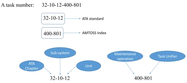
In the AMM, for each of actions such as servicing, removal of parts or system and installing them a task number has been assigned. This task number has the format of XX-XX-XX-XXX-XXX where X is a number. For example, a task number in manual will look like 32-10-12-400-801. Fortunately, no matter who the OEM is, ATA has standardized the first three elements which each consist two digits (XX-XX-XX) in ATA spec 100 standard and later in ATA iSpec 2000 standard with some modifications in ATA spec 100. These standards contains format and guidelines for technical manuals written by aviation manufacturers and suppliers and is used by airlines and other segments of the industry in the maintenance of their respective products. These documents provide standard for aircraft systems numbering, often referred to as ATA system or chapter numbers. First element of a task number is its ATA chapter that refers to a system, the second element is its subsystem (section) and the third element is the unit (subject). Together, these elements identify the applicable aircraft hardware.
The XXX-XXX at the end of the task number is called AMTOSS index (Aircraft Maintenance Task Oriented Support System). The first three digit of AMTOSS, which is the fourth element of a task number, defines the maintenance function being performed. The fifth element of a task number is a three-digit number used to create unique numbers for all tasks or subtasks which are similarly numbered through the first four elements. Tasks are numbered from 801 through 999. Subtasks are numbered from 001 through 800.
At the time of disassembly of aircraft, there are tasks that have the same first three elements (XX-XX-XX). Therefore, one can compare these numbers and verifies that if the disassembly is taken place in a same zone. The definition of zone can go to fewer depths if a user like to choose just two elements (XX-XX). This will lead to wider areas in zones.
Figure 3-1, demonstrates an example of a maintenance task. With considering ATA standardization, we can assign all of tasks that have 32-10-12 at its beginning to a same zone.
Figure 3-1: An example of maintenance task in AMM
3.1.2
AMM structure
AMM contains all of the tasks that address disassembly, assembly, service, inspection, etc. of an aircraft. The subjects in the maintenance manual are divided into following categories:
- Description and Operation - Maintenance Practices - Servicing - Deactivation/Reactivation - Removal/Installation - Adjustment/Test - Inspection/Check 32-10-12 ATA Chapter Sub-system Unit 32-10-12-400-801 A task number: 400-801 Maintenance
operation Task Unifier
32-10-12 400-801
ATA standard AMTOSS Index
- Cleaning/Painting - Repairs
As discussed in previous section, all of these tasks have a task number that is a unique number for that specified task. A task consists all of the procedure that should be performed on an aircraft to satisfy the needed operation. Each task is structured by subtasks and can also refer to other tasks in the AMM.
A subtask is a logical division of a task, and is used to divide tasks into understandable parts. A subtask generally contains only one type of information such as a table, a reference to a task, or a simple procedure. For each subtask same as tasks, a number is assigned but subtasks are not referenced by tasks or other subtasks.
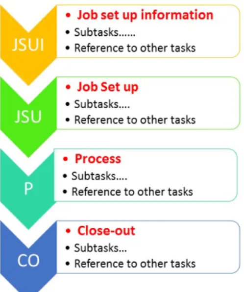
Each of task of AMM has for main sections: - Job Set-Up Information
- Job Set-Up - Procedure - Close-Out
Job Set-Up Information (JSUI): This section of the task consists all of the information and list of
tasks and tools that is required to perform the task. Therefore, in this section an operator can have an overview of the work that should be done.
Job set-up (JSU): This section of the task lists and describe all of the preparation operations and
set-ups before performing the main process.
Process (P): This section is for the subtasks and tasks that the main operations are taking place.
Close-out (Co): This section is for the subtasks that is performed to return the state of the aircraft
to the state which was before performing Job set-up and Process tasks.
It is a remarkable note in AMM that we should pay attention in our disassembly-sequencing problem:
“The steps written within the procedures for the various tasks or subtasks in the AMM are in logical order as interpreted by the Technical Writer. They are correct if followed step by step for the completion of the task or subtask. However, if the intent of the maintenance procedure is not altered and the objective is met, the order of the steps required to complete the task or subtask may be
revised at the discretion of the technician (Example: step 4.f. before step 4.e.). Unless otherwise specified, the elapsed time between the start and the end of a procedure is not important.”
This statement provides a guideline for us:
In our problem, we should consider the precedence logic that is provided in the AMM. Therefor at the time disassembly, tasks and subtasks should be executed in accordance with to order of appearance in the AMM. Figure 3-2 demonstrates a structure of a task in AMM and direction that should be taken for the executing tasks and subtasks.
Furthermore as it was said in previous chapter, the AMM does not provide elapsed times of procedures.
Figure 3-2: Structure of a TASK in AMM 3.1.2.1 Implementation of a task
In AMM, a task is divided to several subtasks. In each of subtasks maybe a procedure is described or maybe along with that procedure it can refer to the other tasks. All of these tasks and subtasks should be implemented in accordance with order of appearance in the AMM.
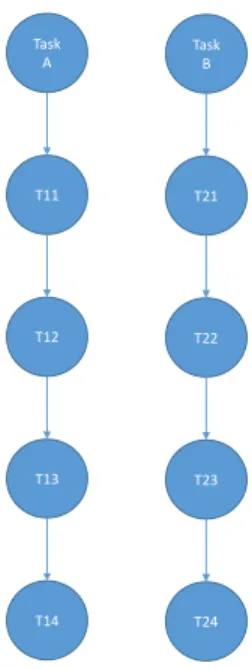
For example lets say we want to implement an imaginary task named: TASK 21-22-23-400-800. Therefore if with referring to AMM it is observed that there are fourteen tasks and subtasks, named T1, T2, …., T14, Figure 3-3 shows the sequence of implementing tasks.
Figure 3-3: Sequence of implementing tasks in AMM
It should be noted that it is possible that each of Tasks or subtasks of T1 to T14 refer to other tasks in AMM. In this case, again same principles applies.
Actually, there are several tasks that are needed to be performed for different tasks and those tasks are not uniquely preformed for a single operation. That is why technical writer of AMM assigns a task name to such kind of tasks and instead of repeating the procedure in text of several tasks, the technical writer just simply refers to name of that task.
At the time of operation, if the operator notices a referral to other task, he or she should find the procedure of implementing that task in AMM.
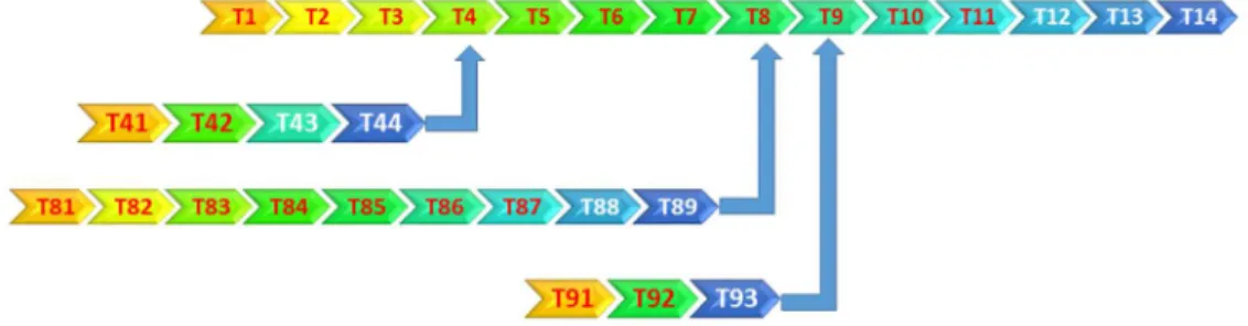
For example of Figure 3-3, any tasks or subtasks of T1 to T14 can refer to other tasks. In this case again same principle of Figure 3-3 applies for those referral tasks and operator should implement all of subtasks and tasks mentioned in AMM for any of T1 to T14 if any. Let us imagine that T4, T8 and T9 refer to other tasks. Figure 3-4: An example of a task with Figure 3-4 demonstrates such this case.
Figure 3-4: An example of a task with referral to other tasks
For above example operator performs T1, T2, T3 and reaches T4. He or she notices that in T4 there is reference to other tasks. Therefore, he/she should implement those tasks before moving to task T5. After tasks T41, T42, T43 and T44 are implemented then T5 should be performed.
After performing T7, its T8’s turn to be executed. It is noticed that there are nine tasks which this tasks or subtask of T8 refers to. Again before being able to implement T9, the operator should execute tasks of T81, T82,…to, T89. The same goes for T9.
The referral to other tasks does not stop here! T41 to T44, T81 to T89 and T91 to T93, are tasks themselves. Any of these tasks can refer to other tasks. Therefore, same principle of previous paragraph applies. For example if T43 refers to other tasks, the operator should implement those tasks before being able to move to T44.
3.1.2.2 Tasks needed from AMM
For our purpose that is an automatic disassembly sequencing, two sections of a Task is required: - Job set-up (JSU) section
- and process (P) section
Job setup information (JSUI) section is not required because it provides an overview of tasks in
next sections. This information is redundant for our purpose and tasks are again repeated in next sections.
It is also important to note that, for our disassembly procedure we do not need to perform tasks in
close-out(CO) sections. AMM states that this section is for returning the status of airplane to what
has been before performing maintenance tasks. In fact, when we are disassembling parts at stage of end-of-life of aircraft, this issue is not our concern anymore.
3.2
Disassembly model in the previous work
3.2.1
Methodology
Ms. Camelot in her thesis and in (Camelot et al., 2013), presented a model for disassembly graph of an EOL aircraft. It supposed to be used in this project for generating automatic disassembly sequences with utilizing the output of code that Mr. Cai had developed, and provides digital database of all of tasks in AMM with their subtask. For this purpose, the author did a very detailed study of the existing model to be utilized. However, it was concluded that Camelot’s model violates AMM procedures. Even though the model tries to respect maintenance procedure implied by the
AMM, but it contains fatal errors. In next paragraph, discussion is provided about fundamental of these errors.
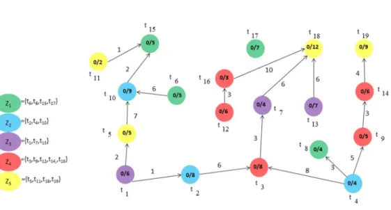
Figure 3-5 demonstrates an imaginary model for a disassembly graph developed by Camelot. Each of tasks from t1 to t19 should be executed and as discussed earlier each of these tasks can have tasks/subtasks. In this model, all of these subtasks of a task are aggregated in one node for each task. To represent this aggregation, on node of each task a fraction with two numbers is provided: The numerator is for status corresponding to the number of executed tasks/subtasks in that node. Obviously, at start of disassembly all of numerators in all nodes are zero. The denominator is total number of tasks/subtasks for that task. For example, t15 has five, t17 has seven, and t18 has 12 subtasks/tasks.
Figure 3-5: An example of disassembly graph model developed by Camelot
Edges represents a link between two nodes (tasks). It is used when one of tasks/subtask of a task calls another task. As shown in Figure 3-6, the number on the edge (m) represents the order of task/subtask in entering edge of node (task i) that calls the task in origin of edge (task j).
Figure 3-6: Edge between two tasks
For example in Figure 3-5, for task t18, its 10th task/subtask calls the task t16 and its sixth task/subtask calls the tasks t7 and t13.
Furthermore, in accordance with three double digit of task number which was discussed before (ATA 2200), for each of nodes/tasks, the zone which that task is executed is colored. In this representation, nodes with same color are those tasks that are in the same zone.
There are other details about this model such as mathematical representation, and how it is used to find an optimal disassembly sequence, which can be found in details in Camelot’s publications. However, provided information to this extend would be enough to explain the problems with the model.
3.2.2
Problems with Camelot’s model:
3.2.2.1 Aggregating subtasks in one node
3.2.2.1.1 Eliminating information about tasks/subtasks
Aggregating subtasks/tasks of a task in one node deletes all the attributes of those subtasks/tasks. In a less important matter, the disassembly model will not provide details of those tasks in that node. For example in Figure 3-5, at the time of disassembly operator is advised that t17 should be executed. This model just tells the operator that t17 has seven subtasks and does not provide any more details for which task should be implemented.