This item was submitted to Loughborough’s Institutional Repository
(
https://dspace.lboro.ac.uk/
) by the author and is made available under the
following Creative Commons Licence conditions.
For the full text of this licence, please go to:
Design of optimal robust fixed-structure controllers
using the quantitative feedback theory approach
G D Halikias1, A C Zolotas2*,andR Nandakumar1
1School of Engineering and Mathematical Sciences, City University, London, UK
2Department of Electronic and Electrical Engineering, Loughborough University, Loughborough, UK
The manuscript was received on 23 May 2006 and was accepted after revision for publication on 5 February 2007. DOI: 10.1243/09596518JSCE305
Abstract: A simple optimization algorithm is proposed for designing fixed-structure controllers for highly uncertain systems. The method can be used to automate the loop-shaping step of the quantitative feedback theory (QFT) design procedure and guarantees robust stability and performance to the feedback loop for all parameters in the plant’s uncertainty set. To avoid over-designing the system, the algorithm can be used to minimize either the asymptotic gain, the open-loop crossover frequency or the 3 dB bandwidth of the closed-loop system (nominal or worst case). The proposed algorithm is illustrated with a design example involving a hydraulic actuator, carried out within a computer aided design (CAD) environment (‘StdQFT’ toolbox) which has been developed by the authors. Some preliminary results of this work appeared in 2002 [1].
Keywords: robust control, quantitative feedback theory, loop-shaping, optimization, hydraulic actuator
1 INTRODUCTION feedback’ [5–7], (b) the ability to take into account phase information in the design process (this is
Quantitative feedback theory (QFT) is a systematic ignored in many norm-based approaches, e.g. H2
robust control design methodology for systems sub- optimal control which is based on singular values),
ject to large parametric or unstructured uncertainty. and (c) the ability to provide ‘transparency’ in the
QFT is a graphical loop-shaping procedure used for design, i.e. clear trade-offcriteria between controller
the control design of either single input–single complexity and the feasibility of the design objectives.
output (SISO) or multiple input–multiple output Note that (c) implies in practice that QFT often
(MIMO) uncertain systems, including the non-linear results in simple controllers that are easy to
and time-varying cases [2] traditionally carried out on implement.
the Nichols chart. The Nichols chart is a useful tool The QFT design procedure is based on the
two-for reading off closed-loop gain and phase directly degree of freedom feedback configuration shown in
from a plot of open-loop logarithmic gain and phase Fig. 1. In this diagramG(p, s) denotes the uncertain
parameterized by frequency. It is widely used in plant, whileK(s) andF(s) denote the feedback
com-classical control and forms an integral part of the pensator and pre-filter respectively that are to be
standard QFT control design procedure [3,4]. Relative designed. Note that model uncertainty is described
to other robust-control design methodologies, QFT by ther-parameter vectorpμPkRrtaking values in
offers a number of advantages, apart from using the setP; it is further assumed that G(p, s) has the
classical control design techniques. These include: same number of right half-plane (RHP) poles for all
(a) the ability to assess quantitatively the ‘cost of pμP. Translating the uncertainty into the frequency
domain gives rise to the plant’s ‘uncertainty templates’, which are the sets
* Corresponding author: Department of Electronic and Electrical Engineering, Loughborough University, Ashby Road, Loughborough
encirclements around it equal to the number of
unstable poles of Lo(s)=G(p
o,s)K(s), and (c) that
no (perturbed) open-loop response crosses the −1
point, i.e. −11 p
vμRK ( jv)G
v (4)
Fig. 1 Feedback configuration
Note that condition (a) is automatically satisfied if
For each fixed frequencyv,Gvdefines a ‘fuzzy region’
K(s) is restricted to be stable and minimum phase,
on the Nichols chart which describes the uncertainty
while conditions (b) and (c) can be easily tested
of the plant at frequency v in terms of magnitude
graphically [8,9]. In practice, a more severe condition
(in dBs) and phase (in degrees). For design purposes,
than (c) is imposed: to establish a minimum amount
Nuncertainty templates are constructed
correspond-of damping, it is required that the nominal open-loop ing to a discrete set of frequenciesV={v1,v2, … ,vN},
frequency response does not penetrate a closed con-chosen to cover adequately the system’s bandwidth.
tour in the Nichols chart (universal high-frequency The robust performance objectives of the design
U-contour). This is constructed from an appropriate
include good tracking of reference input r(s) and
M-circle and information about high-frequency
good attenuation of the disturbance signal d(s)
gain uncertainty of the plant [6]. Formulation of entering at the system’s output, despite the presence
robust stability via the U-contour assumes that at
of uncertainty. The robust tracking objectives are
high frequencies the phase-uncertainty spread of captured by the set of inequalities
the system is minimal, an assumption that is
reasonable for most systems subject to parametric
max
pμP D
K
G(p, jvi)K( jvi) 1+G(p, jvi)K( jvi)
K
dB model uncertainty. If this assumption fails (or if
model uncertainty is in part unstructured) the ∏d(vi))B
u(vi)|dB−Bl(vi)|dB (2) U-contour must be replaced by a set of
frequency-for each i=1, 2, … , N, i.e. if, for each frequency vi, dependent closed templates containing the critical
the maximum variation in the closed-loop gain as point. This does not affect significantly the proposed
pμP does not exceed the maximum allowable method, although for simplicity it is assumed that
spread in specificationsd(vi), typically specified via robust-stability specifications can be formulated via
two appropriate magnitude frequency responses theU-contour.
Bu(v)=|Bu(jv)| and Bl(v)=|Bl(jv)|. Note that it is The robust tracking and disturbance rejection
not necessary to bound the actual gain (but only objectives have been formulated as gain inequalities
the gain spread) since it is assumed that: (a) no of the closed-loop transfer functions (sensitivity
uncertainty is associated with the feedback controller and complementary sensitivity) at the design
fre-K(s) and (b) the pre-filter F(s) can provide arbitrary quencies. For the purposes of QFT design, these
scaling to the closed-loop gain at every frequency. inequalities must be translated into constraints on
The robust disturbance-rejection objective is the nominal open-loop response Lo(jv). This
pro-satisfied by bounding the sensitivity function, i.e. cedure results in a number of contours (‘Horowitz
by imposing constraints of the form tracking templates’ ft
i(w) and ‘Horowitz
disturbance-rejection templates’ fdi(w)) for each frequency vi,
max
pμP
K
1
1+G(p, jvi)K( jvi)
K
∏D(vi) (3) i=1, 2, … , N. These are functions of the phasevari-ablewμ(−360°, 0°]. Thus, robust tracking is satisfied
at frequencyviif and only if|Lo(jvi)|
dBfti(wi) where
for a (subset) of the design frequencies {v1,v2, … ,vN}
argLo(jvi)=wi; similarly, robust disturbance rejection (normally in the low-frequency range). Again these
is attained at frequencyviif and only if |Lo(jvi)| dB are typically specified via an appropriate magnitude
fdi(w). The robust-performance templates (Horowitz
frequency responseD(v)=|D(jv)|.
tracking and disturbance rejection) can be easily Robust stability is enforced by ensuring that: (a)
constructed (within an arbitrary gain tolerance and no unstable pole-zero cancellations occur between
for a discretized phase grid) using a simple bisection
the plant and the controller (for every pμP), (b)
algorithm. This method uses the uncertainty
tem-the nominal open-loop frequency responseLo(jv)=
plates of the plant defined at the design frequencies, G(po, jv)K(jv) (defined for anyp
oμP) does not cross
normally obtained by ‘gridding’ the uncertainty
the−1 point, i.e. the (−180°, 0) point on the Nichols
although more sophisticated methods have been As shown in the last section, the QFT robust-stability and performance objectives can be translated proposed (e.g. references [10] and [11]), and advances
in computational power continuously extend the to graphical constraints on the Nichols chart. The
constraints associated with robust performance class of practical problems that can be addressed
by QFT. (‘Horowitz tracking’ and ‘Horowitz
disturbance-rejection’ templates) correspond to open contours; i.e. In conclusion, assuming that the condition
pro-hibiting unstable pole/zero cancellations between they split the Nichols chart into two regions (for each
design frequency), the high- and low-gain regions. To the plant and the controller is independently verified,
the following conditions guarantee robust stability meet the tracking or disturbance-rejection objective,
each nominal open-loop frequency-response point and performance.
Lo(jvi) must be placed on the high-gain region of
1. The winding number of the nominal open-loop the contour, i.e. forced to satisfy the inequality
systemLo(jv) around the−1 point is equal to the |L
o(jvi)|dBfti(wi) (tracking) or |Lo(jvi)|dBfdi(wi)
number of RHP poles ofLo(s). (disturbance rejection), where argL
o(jvi)=wi. In
2. The nominal open-loop frequency responseLo(jv) contrast, the robust-stability template (U-contour) is
does not penetrate theU-contour. a closed contour containing the critical point. To
3. The following inequalities are satisfied for all construct the U-contour, a start is made from the
i=1, 2, … , n definition of anM-circle (M>1) in the Nyquist plane
(u, v), whereu=Re[Lo(jv)] andv=Re[Lo(jv)] |Lo( jvi)| dBfti(wi) (5) and
K
u+jv 1+u+jvK
=M[A
u+ M2 M2−1B
2 +v2= M2 (M2−1)2 |Lo( jvi)| dBfid(wi) (6) (7)in which wi=argLo(jvi). These inequalities
This is a circle of centre correspond to the robust tracking and robust
disturbance-rejection specifications respectively.
(u,v)=
A
− M2M2−1, 0
B
(8)The paper presents a novel algorithm for designing
fixed-structure controllers that satisfy the QFT and radius
constraints and minimize a measure of system ‘over-design’ (asymptotic gain, crossover frequency,
R= M
M2−1 (9)
closed-loop bandwidth). In section 2 the QFT con-straints are formulated in the form of a feasibility
Since in this case (M>1) the M-circle does not
programme. Section 3 outlines an optimization
contain the origin, it is clear that in the Nichols chart algorithm which can be used to design simple
fixed-it is defined only for an interval of phases, and is structure controllers proportional-integral-derivative
symmetric around the phase linew=−180°. In fact,
(PID), phase lead/lag, second order) in the QFT
drawing the tangents to the circle from the origin, it framework. The algorithm is illustrated in section 3
is clear that (see Fig. 2) with a design example in section 4 involving robust
force control of a hydraulic actuator. Finally, the
y
max=sin−1
A
1M
B
(10)main conclusions of the work appear in section 5.
2 FORMULATION OF QFT CONSTRAINTS
In this section the QFT robust stability and perform-ance constraints are first formulated as a feasibility programme. This leads to an optimization algorithm for carrying out optimal QFT designs using a family of simple fixed-structure compensators. This is in contrast to other approaches (e.g. reference [12]), which optimize the open-loop response of the system in the frequency domain and subsequently
Fig. 2 M-circle in the Nyquist plane (M>1) fit a (potentially high-order) compensator.
and hence the M-circle is defined on the Nichols This gives theU-contour as the union of the graphs of the two functions
chart only for the phase interval
U+(w)=M+(w) and U−(w)=M−(w)−V2 −180°−sin−1
A
1M
B
∏w∏−180°+sin−1A
1M
B
(19)(11) over the phase interval
Next an equation needs to be derived of theM-circle
wl)−180°−sin−1
A
1 MB
in terms of magnitude (m) and phase (w), where
m=√u2+v2 and w=arctanv
u (12) ∏w∏−180°+sin−1
A
1M
B
)wh (20)Referring to Fig. 2, it follows by simple geometry that The ultimate objective of this section is to
charac-terize the regions of the Nichols chart in which the mcosy= M2
M2−1+ M
M2−1cosh open-loop frequency response pointLo(jvi) can lie in
order to satisfy the robust stability and performance constraints. To this purpose define the composite and
function as msiny= M
M2−1sinh (13) fmi (w)=max{fti(w), fdi(w)} (21)
where the maximum is taken pointwise in wμ
Eliminating variable h using the trigonometric
(−360°, 0°]. Further define
identity sin2h+cos2h=1 results in the quadratic
equation fi(w)=
G
fmi (w) forw∏wl (22) max{fmi (w),U+(w)} forwl<w<wh (23) fmi (w) forwwh (24) m2−2M2cosy M2−1 m+ M2 M2−1=0 (14)which can be solved as Also let W
i={w:wl<w<wh, fmi (w)∏U−(w)}. Then,
the robust stability and performance constraints
at frequency vi are satisfied if and only if Lo(jvi)μ
m= M2
M2−1
A
cosy±S
1M2−sin2y
B
(15) RinSi, where
Thus, using the substitution w=−180°−y, the M R
i={Lo( jvi) :|Lo( jvi)|dBfi(w),w=argLo( jvi)}
circle in the Nichols chart is a closed contour which
(25) may be decomposed into the union of the graphs of
the two functions and
Si={Lo( jvi) : fi(w)∏|Lo( jvi)| dB∏U−(w), M+(w)=20 log 10
A
−cosw+S
1 M2−sin2wB
w=argLo( jvi)μWi} (26)An illustration of the regionRinSiis given in Fig. 3.
+20 log 10
A
M2
M2−1
B
(16) Note that, in practice, when a performance constraintis active, then typically Wi=Si=B. This is because
and performance objectives are normally specified at
low frequencies, rarely exceeding the closed-loop bandwidth of the system. However, this formulation M−(w)=20 log
10
A
−cosw−S
1M2−sin2w
B
allows ‘unconstrained’ design frequencies to be takeninto account, i.e. frequencies at which no perform-+20 log
10
A
M2M2−1
B
(17) ance inequalities apply. Such a frequency vi givesfmi (w)=−2 and hence Wi=(wl,wh), Si={Lo(jvi) : |Lo(jvi)|
dB∏U−(w), w=argLo(jvi)μ(wl,wh)} (i.e. the
Following reference [6], theU-contour is obtained by
region below the U-contour), while RinSi would
translatingM−(w) vertically byV2dBs, where
represent the region outside theU-contour.
The conditions that guarantee the robust-stability V2=lim
Appropriate ‘cost functions’ to be minimized include the following quantities:
(a) open-loop crossover frequency (nominal or worst case);
(b) closed-loop bandwidth (nominal or worst case); (c) asymptotic open-loop gain;
(d) A measure of the excess gain-bandwidth area which can be expressed as the integral
A(v1,v2)=
P
v2v1
log|K( jv)|dv
where [v1,v2] is an appropriate frequency interval
Fig. 3 M-circle in the Nichols chart (M>1)
[13,14].
Each of the above measures can be calculated in a
frequencies can now be summarized by the following straightforward manner from the frequency response
two graphical tests. of the system. For example, the open-loop crossover
frequency corresponds to the point where the open-1. The winding number of the nominal open-loop
loop frequency response crosses the 0 dB line on
systemLo(jv) around the−1 point is equal to the
the Nichols chart. The closed-loop bandwidth is the
number of RHP poles ofLo(s).
frequency where the closed-loop gain of the system 2. For each frequencyvi, Lo(jvi)μRinSi.
is 1/√2 (−3 dB approximately). To calculate the
Again, it is assumed that no unstable pole/zero closed-loop bandwidth graphically letL=rexp jwbe
cancellations occur between the controller andG(p, s) the open loop response and set
for every pμP, a condition that must be checked
independently. Of course, similarly to any QFT-based |L|
|1+L|= 1 √2[ r2 1+r2+2rcosw= 1 2 (27) method, these tests do not really guarantee that
Lo(jv) does not enter the U-contour at frequencies
This leads to the quadratic equation r2−2rcosw−
other than the design frequencies. This, however,
1=0 whose only admissible solution is r=cosw+
does not cause a problem in practice, provided a
√cos2w+1. Thus the closed-loop bandwidth of the reasonably large set of design frequencies is selected
system is the frequency at which the open-loop near crossover or, alternatively, by slightly tightening
frequency response crosses the curve the specifications by means of an appropriate
tolerance.
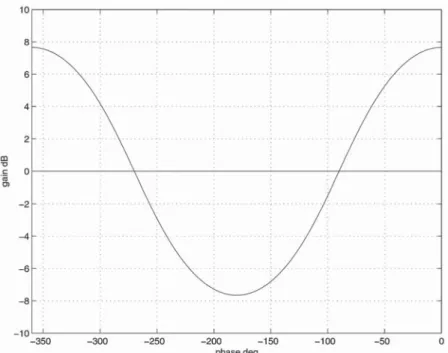
N(w)=20 log
10(cosw+√cos2w+1) (28)
on the Nichols chart, where w denotes open-loop
phase. The curve N(w) is plotted in Fig. 4 over the
3 OPTIMIZATION ALGORITHM
phase interval (−360°, 0°]. Finally, the excess
gain-bandwidth measureA(v1,v2) may be easily calculated
In this section an optimization algorithm is outlined
for designing fixed-structure compensators of certain by numerical integration in terms of the controller
parameters. types subject to the QFT constraints developed
earlier. Every design (i.e. loop shaping ofLo(jv)) that Note that the open-loop response of most systems
encountered in practice crosses the 0 dB line (or satisfies the two graphical tests of the last section is in
principle ‘admissible’, i.e. satisfies the robust-stability curve N(w)) only once. An important exception
consists of systems with lightly damped modes (e.g. and robust-performance objectives. Since in general
many different designs may be admissible, a method flexible structures) exhibiting multiple ‘resonance’
peaks. In such cases the crossover frequency (or is required for classifying them by formulating an
appropriate optimization criterion. Adopting the closed-loop bandwidth) is simply defined as the lowest
frequency at which crossing occurs. The ‘worst-case’
arguments of Horowitz and Sidi [6,7], such a criterion
must penalize the ‘over-design’ of the system, e.g. an crossover frequency or closed-loop bandwidth is
defined as the largest frequency among all uncertain unnecessarily high closed-loop bandwidth, since this
increases the ‘cost of feedback’ in terms of sensor- frequency responses (contained in the uncertainty
template set) crossing the 0 dB line or curve N(w)
noise amplification and potential instability due
Fig. 4 CurveN(w) used to calculate the closed-loop bandwidth
can be easily calculated from the frequency response to tune. Thus optimal controllers of the first two
types may provide simple solutions to robust control of the system, possibly using interpolation techniques
if high accuracy is required. designs based on the QFT method. Note also that
every rational controller of arbitrary complexity can The algorithm presented here generalizes previous
results [1,15] and may be used to automate the loop- be constructed from cascade interconnections of
controllers in (2) and (3) above. Thus, it is possible shaping step of the QFT design algorithm (at least
partially). This is the most demanding step of the to improve the design continuously by building
higher-order controllers in a step-by-step procedure. QFT design procedure [16], for which significant
research effort has been devoted in the recent At each step the optimization algorithm is carried
out (for one of the three controller structures) and literature, e.g. the approach of reference [17] based
on Youla’s-parametrization and linear programming, the resulting optimal controllerK(s) is accumulated
into the nominal open-loop system by redefining the approach of references [18] and [19] which extends
the results of references [20] and [21] to the robust Lo(s)÷Lo(s)K(s). This process may continue until a
satisfactory design is obtained, or until the cost fails QFT framework, techniques that rely on Bode’s
gain-phase integral to impose controller realizability to decrease significantly. Of course, the controller
resulting from this procedure will not, in general, be
constraints [12,13,22], global optimization of PID
controllers using Horowitz bounds [23], etc. Note that optimal over the higher-order controller set.
The proposed algorithm is based on the fact that
these methods are different to those proposed in this
paper, which address loop-shaping in an open-loop fixing the phase of the compensator at two distinct
frequencies determines the compensator uniquelyup
framework using fixed structure controllers.
The types of compensators considered in this paper to scaling. Thus, the phase response of the nominal
open-loop system is also completely determined, are listed below. Note that some of these must be
used under appropriate relative-degree assumptions and only a simple calculation is needed to determine
the minimum amount of gain required to meet the satisfied by the transfer function of the plant.
QFT robust stability and performance specifications
1. PID: K(s)=kp+kds+ki/s and PDD2: K(s)=
(if these are feasible). Geometrically, this corresponds
k1+k2s+k3s2 to shifting the frequency response of
Lo(s) vertically
2. First-order lead/lag: K(s)=k(s+b)/s+a in the Nichols chart by the minimum gain required
3. Second order with complex-poles (zeros): K(s)=
to place the points Lo(jvi) in the RinSi regions
1/s2+2fvns+v2n(ors2+2fvns+v2n)
while simultaneously satisfying the Nyquist stability encirclement criterion. Repeating this procedure for PID [23] and phase-lead/lag controllers are widely
will eventually produce the optimal design (if one (b) If the controller gainskp,ki, andkdare restricted
exists). Next, each controller type is considered in to be non-negative, then the constraints argK(jvi)=
turn. yi and argK(jvj)=yj are feasible if the two scalars
Vij1, Vij2are positive. In this case 3.1 PID and PDD2controllers
argLo( jvk) The classical PID controller is considered first and is
specified by three parameters ki, kd, and kp corre- )w
k=argGo( jvk)
sponding to the integral, derivative and proportional
gains respectively. +arctan
C
vk(vitanyi−vjtanyj)v2i−v2j Theorem 1
−vivj(vjtanyi−vitanyj)
vk(v2i−v2j)
D
(33)(a) Let K(s)=kp+kds+ki/s with kp, kd, and ki
real parameters. Suppose that argK(jvi)=yi and
argK(jvj)=yj, wherevi≠vj. Then the matrix Also,L
o(jvk)μRknSkif and only if (iff) |l|10[fmk(wk)−|Go( jvk)|dB]/20 Cij(vk) Aij=
A
1 − 1 v2i − tan(yi) vi 1 − 1 v2j − tan(yj) vjB
(29) whenwk1[wl wh] has full (row) rank. Let (Vij)=[Vij1 Vij2 Vij3]∞μR3be|l|10[fk(wk)−|Go( jvk)|dB]/20 Cij(vk)
a (real) non-zero vector in the (one-dimensional)
kernel ofAij. Then whenwkμ[wl wh] andfkm(wk)M−(wk) 10[M−(wk)−|Go( jvk)| dB]/20 Cij(vk)
A
kd ki kpB
=lA
Vij1 Vij2 Vij3B
)lA
vitanyi−vjtanyj v2i−v2j vivj(vjtanyi−vitanyj) v21−v2j 1B
|l| 10[fmk(wk)−|Go( jvk)| dB]/20 Cij(vk) (30) orwhere l is an arbitrary real constant. Moreover, the
gain and phase of the controller at any frequency is |l|10[M+(wk)−|Go( jvk)|dB]/20
Cij(vk)
vgiven by
whenwkμ[wl wh] andfmk(wk)<M−(wk)whereCij(vk) is defined in part (a).
|K( jv)|=|l|
S
1+
C
v(vitanyi−vitanyj) v2i−v2j−vivj(vjtanyi−vitanyj)
v(v2i−v2j)
D
2 Proof. (a) The frequency response of the PID
controller is given as
)|l|Cij(v) (31)
K( jv)=kp+jkdv−jki
v (34)
and
argK( jv) with gain and phase
)y(v)=arctan
C
v(vitanyi−vjtanyj)v2i−v2j |K( jv)|=
S
k2 p+A
kdv− Ki vB
2 −vivj(vjtanyi−vitanyj) v(v2i−v2j)D
and (32) argK( jv)=arctanA
kdv−ki/v kpB
(35) respectively.respectively. Now suppose argK(jvi)=yi and used only if the relative degree of the plant is at least two.
argK(jvj)=yjfor two frequenciesvi≠vj. Then
Theorem 1∞ kd−ki
v2i−
kptan(yi)
vi =0 (36)
(a) Let K(s)=k1+k2s+k3s2 with k1, k2, and k3
real parameters. Suppose that the constraints kd−ki
v2j−
kptan(yj)
vj =0 (37) argK(jvi)=yiand argK(jvj)=yjare imposed where
vi≠vjand vitanyj∏vjtanyi. Then all controllers
which can be written in matrix form as of this form are fixed up to a scaling parameter
lμR
and are parametrized as
k1=lvivj(vitanyi−vjtanyj) vjtanyi−vitanyj
A
1 − 1 v2i − tan(yi) vi 1 − 1 v2j − tan(yj) vjB
A
kd ki kpB
=0 (38) k2=l(v2i−v2j) tanyitanyj vjtanyi−vitanyj , k3=lClearly, rank(Aij)=2, sincevi≠vjand thus the
con-troller parameter vector is constrained to lie in the (41)
one-dimensional subspace Ker(Aij). Writing Ker(Aij)=
The magnitude and gain of K(s) at any frequency v
l[Vij1 Vij2 Vij3]∞gives the required expressions forkd,
is given as
ki, and kp from which the magnitude and phase
expressions ofK(jv) follow after some simple algebra. |K( jv)|
(b) It is clear that when the controller gains are
restricted to be non-negative, the scalarsVij1 andVij2
=|l|
S
[(v2i−v2)vjtanyi+(v2−v2j)vitanyj]2 +v2(v2i−v2j) tan2yitan2yj |vjtanyi−vitanyj|
must be non-negative. The conditions for Lo(jvk)μ
RknSkthen follow immediately from the formulation
of the QFT constraints given in the previous section. )|l|Cij(v)
and Theorem 1 shows that fixing the phase of the
PID controller between−90°and 90°at two distinct
argK( jv) frequencies fixes the phase of the controller at every
frequency. The Nyquist plot of the PID controller
=arctan
C
v(v2i−v2j) tanyitanyj(v2i−v2)vjtanyi+(v2−v2j)vitanyj
D
(a vertical straight line with real partkp) shows
geo-metrically that in this case the three controller gains
respectively. are uniquely determined (up to scaling) provided that
−90°<yi<yj<90°forvi<vj. (b) If the controller gainsk
1, k2, andk3are restricted
If the pure-derivative term in the controller is to be non-negative, then the constraints argK(jv
i)=
considered to be undesirable, the controller can be y
i and argK(jvj)=yj with 0<yi<p and 0<yj<p
modified to the form are feasible if and only if (iff)
K∞(s)=kp+ki s+ kds 1+st (39) vitanyi−vjtanyj vjtanyi−vitanyj0 and
where t is a (fixed) sufficiently small parameter. In
this case, Theorem 1 can be applied with minor
modifications by redefining the uncertain plant as (vi−vj) tanyitanyj
vjtanyi−vitanyj 0 (42)
In this case G∞(p,s)=G(p,s)
1+st (40)
argLo( jvk)
and solving for the new variables k∞p=kp+kit,
)wk=argGo( jvk) k∞i=ki,andk∞d=kd+kpt(see reference [15] for details).
Using essentially the same arguments a parallel
+arctan
C
vk(v2i−v2j) tanyitanyj (v2i−v2k)vjtanyi+(v2k−v2j)vitanyjD
result can be obtained for the PDD2 (proportional
derivative–double derivative) controller K(s)=k1+
Also,Lo(jvk)μRknSkiff uniquely asb=b+anda=b++l=−b−. In addition argLo( jvk))wk=argGo( jvk)+arctan
A
vkb
B
|l|10[fmk(wk)−|Go( jvk)|dB]/20 Cij(vk) whenwk1[wl wh] −arctanA
vk aB
(46) |l|10[fk(wk)−|Go( jvk)|dB]/20 Cij(vk) andLo(jvk)μRknSkiff whenwkμ[wl wh] andfmk (wk)M−(wk) k10[fmk(wk)−|Go( jvk)|dB]/20 C(vk) 10[M−(wk)−|Go( jvk)| dB]/20 Cij(vk) whenwk1[wl wh] k10[fk(wk)−|Go( jvk)|dB]/20 C(vk) |l|10[fmk(wk)−|Go( jvk)|dB]/20 Cij(vk) whenwkμ[wl wh] andfkm(wk)M−(wk) or 10[M−(wk)−|Go( jvk)| dB]/20 C(vk) |l|10[M+(wk)−|Go( jvk)|dB]/20 Cij(vk) k10[fmk(wk)−|Go( jvk)|dB]/20 C(vk)whenwkμ[wl wh] andfmk (wk)<M−(wk)whereCij(vk) is defined in part (a).
or Proof. This follows in a similar way to the proof of
k10[M+(wk)−|Go( jvk)|dB]/20 C(vk)
Theorem 1. Similar conclusions can also be drawn about the gain and phase of the open-loop system
when wkμ[wl wh] and fkm(wk)<M−(wk) where and its permissible regions subject to QFT constraints
C(v)=√(b2+v2)/(a2+v2). (details are omitted).
Proof. The frequency response of the phase-lead 3.2 Phase-lead/lag controller controller is given as
Next the case of a first-order phase-lead
(phase-K( jv)=kjv+b
jv+a (47)
advance) controller is considered. The dual result for a phase-lag controller also follows easily.
with the gain and phase Theorem 2
|K( jv)|=k
S
v2+b2v2+a2
LetK(s)=k(s+b)/(s+a) witha>b>0 (‘phase-lead’
controller). Then the constraints argK(jvi)=yi and and
argK(jvj)=yj for two distinct frequencies vi≠vj
with 0<yi<90° and 0<yj<90°are feasible if and argK( jv)=arctan
A
vb
B
−arctanA
va
B
(48) only if the following two conditions are satisfiedrespectively. Now suppose argK(jvi)=yi and
l)(v2i−v2j) tanyitanyj
vitanyj−vjtanyi >0 argK(jvj)=yj are fixed for two frequenciesvi≠vj.
Then and arctan
A
vi bB
−arctanA
vi aB
=yi (49) c)vivj(vjtanyj−vitanyi) vitanyj−vjtanyi <0 (44) arctanA
vj bB
−arctanA
vj aB
=yj (50) In this case, the quadratic equationb2+lb+c=0 (45) Using the trigonometric identity
has one positive root b+ and one negative root b− tan(a−b)= tana−tanb
1+tanatanb (51) and the controller parameters and are determined
gives (after some algebra) Example 1
Consider the following cases.
v2itanyi−via+vib+abtanyi=0 (52)
1. vi=1 rad/s,vj=4 rad/s,yi=10°, andyj=30°. This
v2jtanyj−vja+vjb+abtanyj=0 (53)
gives l=11.9339, c=−66.6806, and so the
con-straints are feasible. The quadratic equation gives
Multiplying the first equation by tanyj, the second
b=b+=4.1467 and a=b++l=−b−=16.0806.
equation by tanyi, and subtracting the resulting two
2. vi=1 rad/s,vj=4 rad/s,yi=60°, andyj=10°. This equations gives
gives l=0.6785, c=0.6083, and the roots of the
quadratic are complex: b1,2=−0.3393±j0.7023.
a=b+(v2i−v2j) tanyitanyj
vitanyj−vjtanyi )b+l (54) The constraints are infeasible.
3. vi=1 rad/s, vj=4 rad/s,yi=−10°, and yj=30°.
Since a>b for a phase-lead controller, then l>0. Clearly the constraints are infeasible for a lead
Substituting for a=b+l in equation (54) leads to (or a lag) controller. This gives l=1.1905,
the quadratic equation c=7.7518, and the quadratic has complex roots
b1,2=−0.5953±j2.7198.
4. vi=1 rad/s,vj=4 rad/s,yi=−10°andyj=−30°. b2+(v2i−v2j) tanyitanyj
vitanyj−vjtanyi b Clearly the constraints are infeasible for a
phase-lead controller (but not for a phase-lag controller). +vivj(vjtanyj−vitanyi)
vitanyj−vjtanyi =0 (55) This gives l=−11.9339, c=−66.6806, while
the quadratic equation gives b+=16.0806 and
b−=−4.1467.
This must have a positive rootb+ if the constraints
are feasible, so that a=b++l>b_=b>0. To see The corresponding result for a phase-lag controller
that at most one of the two roots of the quadratic is as follows. equation
Theorem 2∞ b=−l±√l2−4c
2 (56) Let K(s)=k(s+b)/(s+a) with b>a>0 (‘phase-lag’
controller). Then the constraints argK(jvi)=yi and
argK(jvj)=yj for two distinct frequencies vi≠vj
is positive, note that the transfer functions (s+b)/
with−90°<yi<0°and−90°<yj<0°are feasible if
(s+a) and (s−a)/(s−b) have identical phase
and only if the following two conditions are satisfied
responses; hence, if one root of the quadratic is b,
the other root must be−a. Formally, whenl>0 the
l)(v2i−v2j) tanyitanyj vitanyj−vjtanyi <0 roots of the quadratic can be classified as follows:
c<0: One positive (b+) and one negative (b_) root and
c=0: zero and negative (b=−l) roots
0<c∏l2/4: here √l2−4c<l so both roots are c)vivj(vjtanyj−vitanyi)
vitanyj−vjtanyi <0 (58)
negative
c>l2/4: complex conjugate roots In this case, the quadratic equation
b2+lb+c=0 (59)
Therefore parameters a and b with a>b>0 are
uniquely determined from the two phase conditions has one positive rootb+and one negative rootb−and
whenl>0andc<0. To show thatb−=−anote that the controller parameters b and a are determined
uniquely asb=b+anda=b++l=−b−. In addition
a=b++l=−l+√l2−4c
2 +l argLo( jvk))wk=argGo( jvk)+arctan
A
vk bB
=l+√l2−4c2 =−b− (57) −arctan
A
vka
B
(60)The phase equation for Lo(jvk) is immediate, while andL
o(jvk)μRknSjkiff
the gain inequalities onk forLo(jvk)μRknSk follow directly from the discussion of the previous section
k10[fmk(wk)−|Go( jvk)|dB]/20 C(vk)
whenwk1[wl wh] in which case vn and f are defined uniquely as
vn=√vivjland via equation (62) respectively.
2. If yj=−90° then either of the following two
k10[fk(wk)−|Go( jvk)|dB]/20
C(vk) conditions must hold: y
iμ(−90°, 0°) and vj<vi or yiμ(−180°,−90°) and vj>vi, in addition to whenwkμ[wl wh andfkm(wk)M−(wk) the condition 10[M−(wk)−|Go( jvk)| dB]/20 C(vk) f)(v2j−v2i) tanyi 2vivj <1 (63)
in which case vn andfare uniquely determined
k10[fmk(wk)−|Go( jvk)|dB]/20
C(vk) as
vn=vjand via equation (63) respectively.
3. If yi=−90° then either of the following two
or
conditions must hold: yjμ(−90°, 0°) and vi<vj
or yjμ(−180°,−90°) and vi>vj, in addition to k10[M+(wk)−|Go( jvk)|dB]/20
C(vk) the condition
when wkμ[wl wh] and fkm(wk)<M−(wk) where
f)(v2i−v2j) tanyj
2vivj <1 (64) C(v)=√(b2+v2)/(a2+v2).
in which case vn andfare uniquely determined
Proof. This follows along similar lines to the proof
asvn=viand via equation (64) respectively.
of Theorem 2.
(b) When the phase conditions are feasible then
Theorems 2 and 2∞show that fixing the phases of
the phase-lead or phase-lag controller in the
inter-argLo( jvk))wk=argGo( jvk)+arctan
A
2fvnvk v2n−v2kB
vals (0°, 90°) or (−90°, 0°) respectively determinesuniquely the dynamic part of the controller when the
(65) the constraints are feasible. Feasibility of the
con-straints is easily checked from two sign conditions, andLo(jvk)μRknSkiff
and the controller parameters are determined by
solving a quadratic equation. k10[fmk(wk)−|Go( jvk)|dB]/20
C(vk) whenwk1[wl wh] 3.3 Second-order controller with complex poles
or zeros
k10[fk(wk)−|Go( jvk)|dB]/20 C(vk)
Finally the case is considered of a second-order controller with complex (conjugate) poles. The dual
whenwkμ[wl wh] andfkm(wk)M−(wk) result of a second-order controller with complex
zeros then follows immediately. 10[M−(wk)−|Go( jvk)|
dB]/20 C(vk)
Theorem 3
k10[fmk(wk)−|Go( jvk)|dB]/20 C(vk)
(a) Let K(s)=k/(s2+2fvns+v2n) with vn>0 and
0<f<1 (‘complex-pole second-order lag’). Then the
or constraints argK(jvi)=yiand argK(jvj)=yjfor two distinct frequenciesvi≠vjwith−180°Myi<0°and
k10[M+(wk)−|Go( jvk)|dB]/20 C(vk)
−180°<yj<0°andyi≠yjare feasible if and only if the following conditions are satisfied:
when 1. Ifyi≠−90°andyj≠−90° wkμ[wl wh] and fkm(wk)<M−(wk) whereC(v)=1/√(vn−v)2+4f2v2nv2. l=vjtanyj−vitanyi vitanyj−vjtanyi>0 (61)
Proof. The frequency response of the controller is and given by 0<f)tanyi 2
A
S
vjl vi −S
vi lvjB
<1 (62) K( jv)= k v2n−v2+2jfvnv (66)from which its magnitude and phase responses can (i.e. crossover frequency, closed-loop bandwidth, asymptotic open-loop gain, etc.), so that for each be obtained as
design frequency vi, i=1, 2, … , N, Lo(jvk)μSknRk
and Nyquist’s encirclement criterion is satisfied’.
|K( jv)|= k
√(v2n−v2)2+4f2v2nv2=kC(v) Since for the three types of controllers described
above the phase of the nominal open-loop system is and
completely determined once two controller phases have been fixed, the following algorithm can be used argK( jv)=arctan
A
2fvnvv2n−v2
B
(67) for solving the optimization problem.respectively. Setting argK(jvi)=yiand argK(jvj)=yj
3.4 Optimization algorithm gives
1. Obtain a phase arrayWby discretizing the phase
2fvnvi
v2n−v2i=tanyi and
2fvnvj
v2n−v2j=tanyj interval (−360°, 0°].
2. Select any two distinct frequencies vi and vj in
(68) the set of design frequencies (v
1,v2, … ,vN).
3. Calculate the phase intervalsWkkWandWlkWin
foryi≠−90°andyj≠−90°. Solving simultaneously
which the nominal open-loop phase argLo(jv)
the above two equations gives
can vary atv=vk andv=vl respectively. These
depend on the type of controller to be designed, v2n=vivj(vjtanyj−vitanyi)
vitanyj−vjtanyi (69) e.g. for a PID controller they lie within ±90° of
argG(p
o,vk) and argG(po,vl), etc.
which defines vn uniquely iff l>0. Substituting
4. Initialize anm×narrayFwheremandnare the
into equation (62) then gives the expression forfand
sizes ofWkandWlrespectively, to contain the value
the corresponding condition for an underdamped
of the objective function (crossover frequency,
response (0<f<1). When yj=−90° then vn=vj
closed-loop bandwidth, asymptotic gain, etc.) for
and hencefis given by equation (63). This is positive
each phase pair. Also, initialize m×n controller
when (vj−vi) tanyi>0, from which the two stated
parameter arrays to contain the parameters, conditions follow. Finally, the phase equation for
e.g. (kp, kd, ki) for a PID controller, (ko, a, b) for
Lo(jvk) follows immediately, while the gain conditions
a phase-lead/lag controller, or (ko,vn,f) for a
forLo(jvk)μRknSkcan be derived from the discussion
second-order controller with complex poles/zeros. in the previous section on QFT constraints.
5. For each (Wk(i),Wl(j))μWk×WlkRm×n:
Again, Theorem 3 shows that fixing the phase of (a) Calculate yi=Wk(i)−argG(p
o,vk) and yj=
the controller at two distinct frequencies determines Wl(j)−argG(p
o,vl).
completely the dynamic part of the controller (b) Determine a controller K(s) of one of the
when the constraints are feasible. In the theorem above types, such that argK(jvk)=yi and
formulation the controller is restricted to be under- argK(jvl)=yj. If these phase constraints are
damped. This restriction can be removed, if required, infeasible, setF(i, j)=2and consider the next
by ignoring throughout thef<1 condition. An almost phase pair (Wk(i),Wl(j)).
identical procedure may be used to determine the (c) Find the minimum value of gain ko>0 such
dynamic part of a minimum-phase non-proper that Lo(jvq)=koK(jvq)G(p
o, jvq)μRqnSq for
controllerk(s2+2fvns+v2n) from its two phases in allq=1, 2, … , NandLo(jv) satisfies Nyquist’s
the interval (0°, 180°) at two distinct frequencies vi encirclement criterion. If no such gain ko
andvj; details are omitted. exists, set F(i, j)=2 and consider the next
In all three cases considered above simple gain phase pair (Wk(i),Wl(j)).
conditions on the nominal open-loop gain have (d) Calculate the value of the objective function
been derived, so that the QFT robust stability and (crossover frequency, closed-loop bandwidth,
performance constraints are satisfied. These are of asymptotic gain, etc.) corresponding to the
the form Lo(jvk)μRknSk, which for a fixed phase designed Lo(jv) and assign it to the (i, j)th
argLo(jvk)=wkcorrespond to gain intervals element of F. Save also the controller
para-meters to the corresponding entries of the [k1(vi,wk),k2(vi,wk)]n[k3(vi,wk),2] (70)
parameter arrays.
6. At the end of allm×n iterations, calculate co=
wherei=1, 2, … , N. Thus the optimization problem
takes the form: ‘Minimize the optimization criterion min(i,j)μW
the QFT constraints are infeasible; otherwise the performance bounds may be calculated exactly at these phases to arbitrary accuracy using a
optimal cost is co and the optimal controller
parameters can be obtained from the (i*, j*)th bisection algorithm implemented between steps
5(b) and 5(c). In practice, however, it is sufficient
elements of the controller-parameter arrays.
to substitute each point with the one that is closest A few remarks can be made on the algorithm.
on the predefined phase grid. 1. In step 1 of the algorithm the phase discretization
of the interval (−360°, 0°] results in a phase gridW,
typically equally spaced. In practice, 50–100 phases 4 DESIGN EXAMPLE
are adequate. It is helpful to calculate the
per-formance bounds (‘Horowitz tracking’, ‘Horowitz In this example some of the techniques described
above are applied for designing a robust force
con-disturbance-rejection’ templates and U-contour)
over the same phase grid. troller for a non-linear hydraulic actuator interacting
with an uncertain environment. The linearized model
2. In principle any two frequencies vk and vl
can be selected from the set of design frequencies of the actuator is based on references [25] and [26]
from where full modelling details can be found. A in step 2. In general, selecting these frequencies
reasonably far apart (for minimum numerical schematic of the hydraulic actuator is shown in Fig. 5.
Uncertainty in the model arises from variations in sensitivity) works well in practice. A common-sense
rule is to choose frequencies at which the controller operating-point dependent parameters, changes in
the environment, and changes in the hydraulic can introduce a wide range of phase without
con-flicting with the QFT constraints or the expected actuator’s functions.
characteristics of the system; for example, if the
nominal plant is of type zero and the controller 4.1 Controller design
introduces integral action, the open-loop phase at
The overall transfer function between the measured
very low frequencies will be near −90 degrees,
contact forceF(s) and applied control voltageV(s) is
and therefore frequencies in this range should not
given as be selected.
3. In steps 3 and 5(a) of the algorithm all phase
G(s)=F(s) V(s)=
k sp ts+1
calculations can be performed modulo −360°.
This restricts the phase interval of interest to the
range (−360°, 0°]. ×
C
Kske(Ai+Ao)(Kp+Cs)(mas2+ds+ke)+(A2i+A2o)s
D
4. Since the phase of Lo(jv) is completely
deter-mined when two controller phases are fixed, the
Hereksanddsrepresent sensor stiffness and damping
calculation of the minimum gain in step 5(c) is
respectively. The sensor connects the actuator’s
straightforward. For example, one possible method piston of mass
mato the environment, represented
is to calculate the minimum distance between the by a mass
me, stiffnesske, and dampingde. Further, plant and the corresponding ‘open’ performance
AiandAorepresent the effective inner and outer areas
bounds and check whether this amount of gain of the piston,
tandkspare gains describing the valve
brings the high design frequencies within the dynamics, while
Ks and Kp are load and
pressure-U-contour, together with a stability test. Checking dependent variables, respectively. Finally, parameter the total number of encirclements required for
stability is also straightforward and can be per-formed by purely graphical means (i.e. by
count-ing the crosscount-ings of the −180° line and their
directions). See references [8] and [9] for details. Note also that a frequency grid ‘denser’ than the set of design frequencies must typically be used for this purpose.
5. Step 5(c) requires the calculations of the perform-ance bounds at arbitrary phases, which may not
coincide with the discretized phases of array W.
There is no difficulty, however, in estimating the
performance gains from adjacent phase points, Fig. 5 Diagram of the hydraulic actuator (based on
reference [25]) e.g. using linear interpolation. Alternatively, the
C is a constant arising from the linearization and procedure around a specified operating point,
defined as B l(s)= 1 (s/4.8+1)(s/80+1)(s2/50+9.6s/50+1) C=1 b
A
V9i+V9o2
B
These were obtained by step-response figures ofmerit related to rise-time, percentage overshoot, and
where V9i and V9o represent the initial volumes of settling time (for full details refer to reference [25]).
hydraulic fluid trapped in the blind and the rod sides Thus the design specifications for the feedback
of the piston andbis the effective bulk modulus of controllerK(s) are
the fluid. The remaining variables defined in Fig. 5
are:x(piston displacement),xe(load–mass
displace-max
pμP
K
G(p, jvi)K( jvi) 1+G(p, jvi)K( jvi)
K
dB
ment), pi and po (input and output line pressures
respectively),qiandqo(fluid flowrates into and out
∏|Bu( jvi)|
dB−|Bi( jvi)|dB
of the valve respectively), ps and pe (pump and
return – exit – pressures respectively), andxsp(spool
which should hold for all design frequencies inVand
displacement).
for every possible combination of the ten uncertain A list of all parameters defining the linearized
parameters varying over their respective ranges transfer function is given in Table 1. For each
specified in Table 1. Further, it is required that the parameter a minimum, maximum and nominal
open-loop frequency response (for any permissible value is given. The parameters are assumed to vary
combination of parameters) should not enter the independently between their corresponding extreme
M=1.4 circle, which gives the design an approximate
values.
gain margin of 3 dB. Finally, since for hydraulic
The uncertainty inKsandKpreflects variations in
actuators of this type the valve dead-band typically the operating point (especially the non-linearity
produces a steady state error in the system response arising at the interface between positive and negative
[25], integral action is required from the feedback spool displacements), supply pressure, and orifice
controller to eliminate the steady state error.
area gradient. Uncertainty in parameters ke and d
The uncertainty templates of the model were
model variations in environmental stiffness and
first obtained by using a three-point grid for each damping, while uncertainty in valve characteristics
uncertain parameter (nominal, minimum, and
maxi-is modelled by variations in parameters t and ksp
mum values). This resulted in 310=59 049 uncertain
[25]. Variations in parameterCreflect changes in the
points in the Nichols chart for each template. To fluid bulk modules and the volumes of the fluid
reduce the number of subsequent calculations, the trapped at the sides of the actuator. All these
para-convex hull of each uncertainty template was also
meters are known to affect the dynamic stability of
obtained and used to derive the Horowitz bounds at the system.
each design frequency. This process introduces some Following reference [25], the design frequencies
measure of conservativeness to the design, as the
were chosen asV={0.01, 0.05, 0.1, 0.5, 15, 10, 50, 70,
uncertainty templates need not be convex, which in 100} rad/s. The robust tracking bounds are defined by
this case, however, is minimal. the magnitude frequency response of the two systems
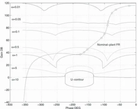
The Horowitz bounds were next calculated numerically at the ten design frequencies, with a Bu(s)= s/2.8+1
(s/4+1)(s/7+1)(s/8+1) gain tolerance of 0.1 dB and a phase step of 1°. This
was followed by the construction of the U-contour,
corresponding to an M-circle with M=1.4 and a
Table 1 Operating values and parameter ranges
high-frequency uncertainty spread ofV2=11.03 dB,
Parameter Nominal value Range
calculated analytically from the model. The
corre-ke 75 kN/m 50–100 sponding contours are shown in Fig. 6, together with
Ks 0.375 m3/Pa s 0.25–0.5 the nominal frequency response of the plant (the ten
Kp 2.5×10⁻¹²m2/s 0–5×10⁻¹²
design frequencies being marked with a circle). C 1.5×10⁻¹¹m3/Pa 1×10⁻¹¹–3×10⁻¹¹
d 700 N/m s 600–800 Note that only the first seven design frequencies
ma 20 kg 19.9–20.1
correspond to open Horowitz templates.
Ai 0.002 03 m2 0.001 93–0.002 13
The design specifications indicate that integral
Ao 0.001 52 m2 0.001 44–0.001 60
ksp 0.0012 m/V 0.0011–0.0013 action must be introduced via the feedback controller.
t 35 ms 30–40
Fig. 6 Nominal-plant frequency response, Horowitz templates, andU-contour
controller using the results of Theorem 1, which seven points lying on or above the corresponding
templates, the last three (high frequencies corre-proved to be infeasible. The reason in clear from
Fig. 6, which indicates that a large amount of phase sponding to the closed Horowitz contours) lying
out-side or on theU-template. It may be seen, however,
advance (exceeding 90°) should be introduced in
the mid–high frequency range. Thus the controller that the nominal frequency response penetrates
theU-contour between the two consecutive design structure was modified as
frequencies v=10 and v=50 rad/s. This is a
common problem with QFT design which is based on K1(s)=k1+k2s+k3s2
s(s/130+1) a discrete set of design frequencies. A typical remedy
is to define a more dense set of design frequencies or
Thes-term in the denominator provides the required
tighten the specifications. Here a simpler technique integral action, while the numerator is a PDD2
was followed by adding an additional first-order lag (proportional derivative–double derivative) term
term to the controller, to modify the open-loop
providing sufficient phase advance (up to 180° at
response in the offending frequency range 10∏v∏
high frequencies). The additional pole at s=−130
50 rad/s. The overall controller is was introduced to ensure that the controller is
proper. The optimal location of this additional pole
K(s)=(0.0004+0.002s+4.9778×10⁻⁵s2)(0.06231s+1) s(s/130+1)(0.1295s+1)
could be optimized using this method, although its
effects in this case are minimal. Next, the denominator
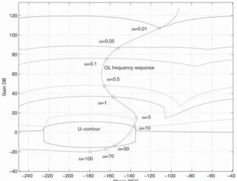
term ofK1(s) was absorbed by the nominal plant, and The corresponding open-loop response is shown in
Fig. 8. The nominal open-loop system has a
cross-the three parameters k1, k2, and k3 were optimized
using the algorithm of section 3 and the results of over frequency of 16.91 rad/s and a 3 dB closed-loop
bandwidth equal to 28.21 rad/s.
Theorem 1∞. The cost function chosen for optimization
was the open-loop asymptotic gain (controlled byk3). The controller designed using the proposed
opti-mization method is remarkably similar to the one The new optimization problem proved feasible and
resulted in an optimal PDD2-controller with designed manually in reference [25] (the controller
in reference [25] was also validated experimentally). k*1=0.004, k*2=0.002, k*3=4.9778×10⁻⁵ This suggests that the design specifications in this case are tight. Moreover, the similarity can be further The resulting open-loop system is shown in Fig. 7.
It can be seen that the design specifications at illustrated in Figs 9 and 10, comparing the magnitude
and phase responses of both the optimized and all ten design frequencies are satisfied, the first
Fig. 7 Nominal open-loop response with the PDD2optimal controller
Fig. 8 Nominal open-loop response with the modified PDD2optimal controller
manually designed controllers. The optimized con- of the two designs. This illustrates the usefulness of
this method for designing controllers for practical troller is able to meet the robust performance
specifications with less gain at low frequencies (of systems.
around 4 dB) but has a lower roll-off rate at high
frequencies. The phase responses of the two
con-4.2 Pre-filter design trollers are also similar; they both inject phase lag
at low frequencies (due to their integral action) The ultimate step of the QFT design is to design a
pre-filter. Here the following procedure was used. and provide maximum phase advance in the range
Fig. 9 Magnitude response comparison of the proposed optimized and manual-designed (from reference [25]) controllers
Fig. 10 Phase response comparison of the proposed optimized and manual-designed (from reference [25]) controllers
open-loop uncertain systems were plotted (see frequencies. The values obtained are summarized in
Tables 2 and 3. Fig. 11). These correspond to the five more important
parameters (in terms of the uncertainty template As expected, the spread in the closed-loop gain is
within the required tolerances; thus all responses can spread), the remaining five parameters being fixed
to their nominal value. Next, the maximum and be brought between the specified lower and upper
bounds by designing a pre-filter that essentially minimum gains were recorded at the ten design


![Fig. 10 Phase response comparison of the proposed optimized and manual-designed (from reference [25]) controllers](https://thumb-us.123doks.com/thumbv2/123dok_us/9716081.2853179/18.892.242.645.612.923/phase-response-comparison-proposed-optimized-designed-reference-controllers.webp)


