2012
A Hardware-Software Integrated Solution for
Improved Single-Instruction Multi-Thread
Processor Efficiency
Michael Steffen
Iowa State UniversityFollow this and additional works at:
https://lib.dr.iastate.edu/etd
Part of the
Computer Engineering Commons
This Dissertation is brought to you for free and open access by the Iowa State University Capstones, Theses and Dissertations at Iowa State University Digital Repository. It has been accepted for inclusion in Graduate Theses and Dissertations by an authorized administrator of Iowa State University Digital Repository. For more information, please [email protected].
Recommended Citation
Steffen, Michael, "A Hardware-Software Integrated Solution for Improved Single-Instruction Multi-Thread Processor Efficiency" (2012).Graduate Theses and Dissertations. 12639.
multi-thread processor efficiency
by
Michael Anthony Steffen
A dissertation submitted to the graduate faculty
in partial fulfillment of the requirements for the degree of
DOCTOR OF PHILOSOPHY
Major: Computer Engineering
Program of Study Committee:
Joseph A. Zambreno, Major Professor
Srinivas Aluru
Morris Chang
Akhilesh Tyagi
Zhao Zhang
Iowa State University
Ames, Iowa
2012
DEDICATION
This thesis is dedicated to my parents
for their continuous encouragement and support in my education
and
also dedicated to my wife
TABLE OF CONTENTS LIST OF TABLES . . . v LIST OF FIGURES . . . vi ACKNOWLEDGEMENTS . . . xii ABSTRACT . . . xiii CHAPTER 1. Introduction . . . 1
CHAPTER 2. Streaming Processor Architecture . . . 5
2.1 SIMT Processor Architecture . . . 5
2.2 Thread Control Flow Divergence . . . 7
CHAPTER 3. Literature Review . . . 10
3.1 GPGPU-Computing . . . 10
3.2 Warp Control Flow . . . 11
CHAPTER 4. Hyper-threaded SIMT Cores . . . 15
4.1 Warp Divergence . . . 16
4.1.1 Parallel Execution of Diverged Warps . . . 18
4.2 SIMT Hyper-Threading Architecture . . . 19
4.2.1 Stack Manipulation Algorithms . . . 21
CHAPTER 5. Dynamic µ-Kernel Architecture . . . 26
5.1 Memory Organization . . . 27
5.1.1 Thread Usage of Spawn Memory . . . 28
5.1.2 Partial Warp Formation . . . 29
5.3 Warp Formation . . . 29
5.4 Scheduling . . . 31
5.5 Programming Model for Dynamic µ-Kernels . . . 33
CHAPTER 6. CUDA Supported µ-Kernel . . . 36
6.1 CUDA Thread Hierarchy . . . 36
6.2 Improved Thread Spawning . . . 37
6.2.1 Run-time Performance Model Execution . . . 37
6.2.2 Divergence Instruction Hardware . . . 40
6.3 Performance Model . . . 41
CHAPTER 7. Experimental Setup . . . 44
7.1 SIMT Hyper-threading . . . 44
7.2 µ-kernels Setup . . . 44
7.2.1 Benchmark Kernels . . . 46
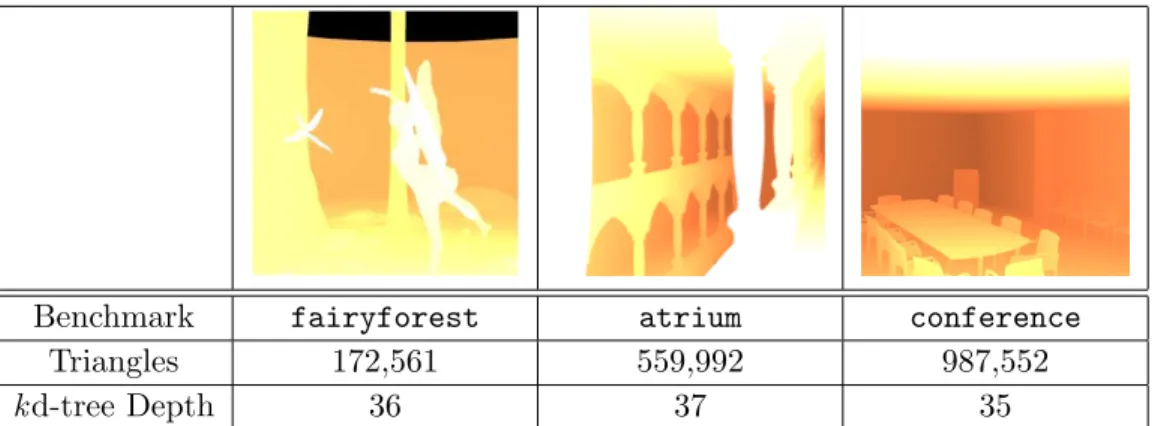
7.2.2 Benchmark Scenes . . . 47
7.3 CUDA Supported µ-Kernels . . . 48
CHAPTER 8. Experimental Results . . . 50
8.1 SIMT Hyper-threading . . . 50
8.2 Dynamic Micro-Kernel Results . . . 52
8.3 CUDA Supported Micro-kernels . . . 57
CHAPTER 9. Future Work . . . 62
9.0.1 Spawn Memory Caching . . . 62
9.0.2 Register and Shared Memory Utilization . . . 62
9.1 Programmable Thread Grouping . . . 63
9.2 Programming Model for Spawning Threads . . . 64
CHAPTER 10. Conclusions . . . 65
APPENDIX A. Hardware Accelerated Ray Tracing Data Structure . . . 67
LIST OF TABLES
7.1 Hardware Configuration of the Simulator . . . 45
7.2 Simulated Benchmarks. . . 45
7.3 Configuration used for simulation. . . 46
7.4 Kernel processor resource requirements per thread. . . 47
7.5 Benchmark scenes with object count and tree data structure parameters. 48 7.6 Hardware Configuration of the Simulator . . . 48
8.1 Memory bandwidth requirements for drawing a single image without caching. Values are calculated from the number of tree traversal oper-ations and intersection tests. . . 58
A.1 GrUG performance parameters for each fixed hardware pipeline stage. 80
LIST OF FIGURES
2.1 Single streaming multiprocessor architecture composed of multiple stream
processors. . . 6
2.2 PDOM branching efficiency for a single warp performing a looping
op-eration. . . 7
2.3 Divergence breakdown for warps using traditional SIMT branching
meth-ods for theconference benchmark. Higher values in the key represent
more threads that are active within a warp. This figure was created
using AerialVision [5]. . . 9
3.1 NVIDIA’s GPU Theoretical GFLOP performance compared to Intel
CPU’s. This figure is from NVIDIA’s CUDA C Programming Guide [50]. 11
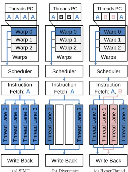
4.1 Single-Instruction Multiple-Thread Architecture for processing a warp. a) No
thread Divergence. b) Thread divergence. c) Our 2 way hyper-threading
ar-chitecture. . . 16
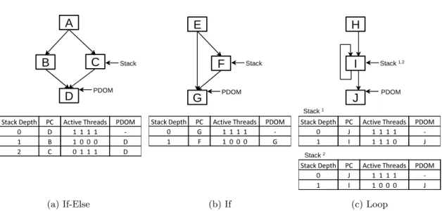
4.2 Different categories of warp divergence. (a) results in two different control flow
paths before all threads reconverge at ‘D’. (b) Only a single diverging control flow is required before threads reconverge at ‘G’. (c) A looping operation where one iteration has 3 threads active and a later iteration has 1 thread. Similar
4.3 Example application containing multiple diverging loops where threads
run a varying number of iterations per loops. In PDOM, the second
loop can only be run after all threads finish the first loop. Using
Hyper-threading, threads that finish the first loop can begin executing the
second loop before all threads finish the first loop. . . 18
4.4 Warp meta-data fields for both PDOM and hyper-threading warps.
Conventional SIMT warps only requiring knowing a single instruction
PC and what threads out of the warp requiring executing this PC. For
hyper-threaded warps, multiple instruction PCs are required in
addi-tion to expanding the active thread mask to indicate which threads are
active and which instruction PC is required. . . 20
4.5 SIMT 2 way hyper-threading architecture resulting in two virtual
pro-cessors. . . 21
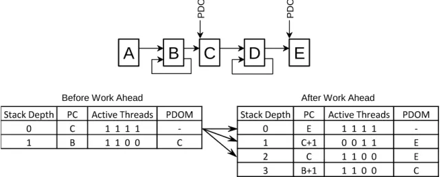
4.6 Sample stack modification for allowing threads at a PDOM point to
work ahead. The PDOM stack entry (depth 0) is split into three new
stack entries: 1) For the next PDOM to reconverge all threads back
together. 2) Stack entry for threads working ahead. 3) Stack entry to
progress threads currently not at PDOM point to progress to the next
PDOM point. . . 23
4.7 Warp stack layout used for spatial subdivision stack management
al-gorithm. This layout is designed to mimic smaller warps using
hyper-threading. . . 25
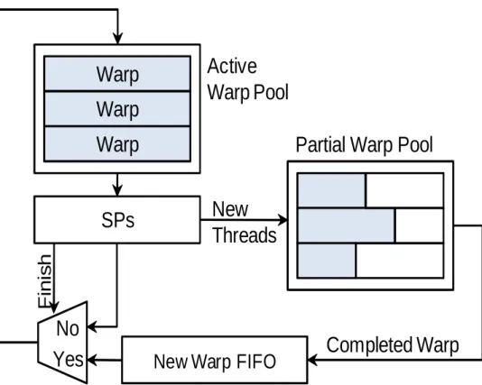
5.1 Dynamic thread creation hardware overview. New threads created by
the SPs are placed into new warps waiting in the partial warp pool.
Once enough threads have been created to complete a warp, the warp
5.2 Architecture for the spawn instruction. Dynamically created threads
identify existing threads that will follow the same control path using a
look-up table. Once the warp has been identified for the new threads,
the memory pointers are stored in memory for later use. . . 30
5.3 Spawn memory layout for threads accessing parent thread data using 4
threads per-warp and 8 bytes of storage between threads. Child threads
use their special register to access the warp formation data. The warp
formation data is a memory pointer to the parent thread data. . . 35
6.1 Potential processor efficiency lose from using Micro-Kernels. The nested
branch-ing operation at C uses the spawn branchbranch-ing method. Thread reconvergbranch-ing at block F see less efficiency then using PDOM branching at C since their are no
threads to reconverge with. . . 38
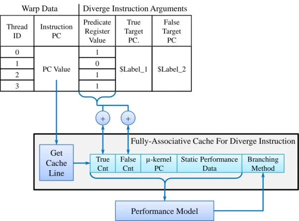
6.2 Implementation for the diverge instruction and updating parameters used by
the performance model. . . 41
8.1 Limitations on the performance gain using hyper-threading on warps. 51
8.2 2-way hyper-threading results. . . 52
8.3 Effects on performance with increasing hyper-threading virtual
proces-sor count. . . 53
8.4 Comparing performance results of using hyper-threading and smaller
warp sizes. . . 54
8.5 Hyper-threading results using existing SIMT memory systems . . . 55
8.6 Divergence breakdown for warps using µ-kernels for the conference
benchmark. Warps are able to keep more threads active by creating
new warps at critical branching points. . . 56
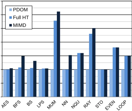
8.7 Performance results for all benchmarks using different branching and
8.8 Divergence breakdown for warps using dynamic thread creation with
bank conflicts for the conference benchmark. Warps still maintain
more active threads over traditional branching methods, however,
addi-tional pipeline stalls are introduced by bank conflicts. . . 59
8.9 Branching performance for the conference benchmark. Theoretical
results were simulated with an ideal memory system. . . 59
8.10 Performance for all warps diverging with different percentage of threads going
to the two different branches. As we have more threads executing the shorter of the path, we expect higher performance since our method will perform fewer
instructions.. . . 60
8.11 Performance for 50% of threads diverging in a warp with different percentage
of warps diverging in a block. As we go to lower number of warps diverging we have fewer threads to form new warps, PDOM performance starts to be the
better branching method. . . 60
8.12 Performance results for 50% of threads diverging in a warp with different
num-ber of instructions after reconvergence point. As the numnum-ber of instructions after reconvergence increases above three times the branching instructions,
PDOM becomes more efficient whenreconverge instructions are not used. . 61
A.1 GrUG data structure composed of a uniform grid for the top layer and
a lower layer that maps to a HS3 tree structure. . . 71
A.2 Hash function starting with X,Y,Z coordinates in integer format and
producing the data structure that contains geometry information for
intersection testing. . . 73
A.3 Variables needed for DDA traversal. . . 75
A.4 Architecture of Grouped Uniform Grid . . . 77
A.5 Integration of the GrUG pipeline into a multi-core graphics processor
and the fixed hardware stages for the GrUG pipeline. . . 79
A.7 Benchmark data for each scene and the total memory required by the
data structure. . . 82
A.8 The memory requirements of GrUG compared tokd-tree. . . 83
A.9 Number of memory reads required for traversing GrUG and kd-tree. . 84
A.10 Total number of instructions executed for traversal of visible rays. k
d-tree results are compared against GrUG using grid sizes of 512, 256 and
128. . . 86
A.11 Number of completed rays for the first 300,000 clock cycles of the
Con-ference benchmark scene. . . 87
A.12 Memory requirements forkd-tree and GrUG. . . 88
A.13 Ratio of the performance increase divided by the memory overhead for
different benchmarks and grid sizes. Performance increase and memory
overhead are based on thekd-tree algorithm resulting in a value of 1.0
for thekd-tree. . . 89
A.14 Memory bandwidth per frame required to render visible rays without
caching. . . 90
B.1 FPGA architecture framework provided to students. Students were responsible
for implementing code in the graphics pipe sub-unit. . . 94
B.2 The protocol for sending data from the workstation to the FPGA. This format
represents the first 32-bit message in a packet. . . 96
B.3 Format of how vertex attributes are sent to the FPGA and then stored in
memory. The index queue stores address for the vertex and color queue for
each vertex. . . 99
B.4 Sample student OpenGL application that draws a 2D video game using pixels. 100
B.5 Transformation process for converting 3D OpenGL coordinates to screen
coor-dinates. . . 101
B.6 A rasterization zig-zag pattern implemented by students to identify all pixels
B.7 OpenGL application used to test all 8 depth functions. Each horizontal bar
uses a different depth function test. The black color is a plane at depth 0 and
the red and blue colors are a sin wave with depths from -1 to 1. . . 106
ACKNOWLEDGEMENTS
First, thanks to my advisor, Professor Joseph Zambreno for his guidance in my research
and professional development as well as for additional opportunities to pursue my interests
in engineering education. Thanks also to Professor Jeffrey Will at Valparaiso University for
his encouragement and mentorship when my interest in computer engineering first sparked.
I also thank Professor Srinivas Aluru, Professor Morris Chang, Professor Akhilesh Tyagi and
Professor Zhao Zhang for serving on my Preliminary and Final Examination committee.
This work was partly funded by the National Science Foundation (NSF) Graduate Research
ABSTRACT
This thesis proposes using an integrated hardware-software solution for improving
Single-Instruction Multiple-Thread branching efficiency. Unlike current SIMT hardware branching
architectures, this hardware-software solution allows programmers the ability to fine tune
branching behavior for their application or allow the compiler to implement a generic software
solution. To support a wide range of SIMT applications with different control flow properties,
three branching methods are implemented in hardware with configurable software instructions.
The three branching methods are the contemporary Immediate Post-Dominator Re-convergence
that is currently implemented in SIMT processors, a proposed Hyper-threaded SIMT
proces-sor for maintaining statically allocated thread warps and a proposed Dynamic µ-Kernels that
modified thread warps during run-time execution. Each of the implemented branching methods
have their strengths and weaknesses and result in different performance improvements
depend-ing on the application. SIMT hyper-threaddepend-ing turns a sdepend-ingle SIMT processor core into multiple
virtual processors. These virtual processors run divergent control flow paths in parallel with
threads from the same warp. Controlling how the virtual processor cores are created is done
using a per-warp stack that is managed through software instructions. Dynamicµ-Kernels
cre-ate new threads at run-time to execute divergent control flow paths instead of using branching
instructions. A spawn instruction is used to create threads at run-time and once created are
placed into new warps with similar threads following the same control flow path.
This thesis’s integrated hardware-software branching architectures are evaluated using
mul-tiple realistic benchmarks with varying control flow divergence. Synthetic benchmarks are also
used for evaluation and are designed to test specific branching conditions and isolate common
branching behaviors. Each of the hardware implemented branching solutions are tested in
iso-lation using different software algorithms. Results show improved performance for divergent
CHAPTER 1. Introduction
Single-Instruction Multiple-Thread (SIMT) processor architectures are used for large
data-parallel applications since they are designed to be scalable to very high processor core counts.
Thread level parallelism (TLP) is also commonly associated with SIMT to support even larger
quantities of parallel threads to help hide individual thread latencies. As an example, NVIDIA’s
GeForce GTX 590 [46] SIMT processor has 1024 thread processor cores and supports TLP of
32-threads per thread-core. To support these high core counts, SIMT architectures impose
additional structure on multi-threaded applications and introduce some simplifications to
con-ventional processor datapaths that can negatively impact performance. These limitations on
program structure often require new algorithms to be developed for improving SIMT
perfor-mance; making the porting process for existing algorithms to SIMT difficult [36]. Similarly,
while many algorithms have been developed for SIMT processors, (see the over 1,000
applica-tions and papers reported by the NVIDIA CUDA Community Showcase [49]), performance is
often less than the expected Amdahl’s speedup, mainly for architectural reasons.
To manage the large number of threads (32,768 for the GeForce GTX 590), threads are
organized into blocks dictated by the programming model and an entire block is scheduled onto
one of the SIMT core processors. When threads are assigned to a SIMT core they are statically
grouped into warps. SIMT cores use warps as the scheduling entry instead of individual threads.
When a warp is scheduled, all threads inside the warp are executed in their own processing
lane but share scheduling and instruction fetching hardware. The GeForce GTX 590 has 32
SIMT core processors each configured to support a warp size of 32 threads.
Individual threads are allowed to execute control flow instructions, even for threads inside
the same warp. Control flow divergence can then occur when threads inside the same warp
only a single instruction can be fetched for all threads in a warp, all required control flow paths
are executed and threads not requiring the current path being executed are disabled (decreasing
the IPC). Reconvergence algorithms are implemented to minimize the time spent in diverging
control flow paths. However, processor utilization still decreases as not all of the processing
lanes can be utilized due to disabled threads.
Consider, for example, physically-based global rendering algorithms, that seek to produce
highly realistic images through the modeling of the physics of light transport [53]. Conceptually,
these global rendering algorithms map nicely to wide SIMT hardware, since individual pixels
can be represented by a single thread, resulting in thousands of individual threads with no
inter-thread data dependencies. These inter-threads can then be mapped to one of the many parallel cores
that can switch between threads at minimal cost [9, 55]. In practice, however, global rendering
algorithms require large amounts of memory bandwidth as well as complex scalar thread flow
(i.e. branching). While fixed hardware solutions such as AppendixAcan improve performance,
these implementations are not generic enough for other types of algorithms. Results from SIMT
execution on NVIDIA GPUs show that performance is typically limited by the complex control
flow and not the memory bandwidth requirements [1]. Gobal rendering algorithms are just one
of many types of algorithms that have difficulty achieving significant performance increases on
SIMT architectures and any application requiring control flow instructions will see some degree
of performance degradation.
To reduce the performance loss from branching, this thesis proposes using integrated
hard-ware/software branching methods that allow developers to fine tune branching behavior for
the application. By including a software component to branching behavior, developers have
full control over the instructions being used for each branch in their application or can allow
a compiler to implement generic branching solutions. To be able to use hardware/software
branching methods, this thesis also introduces two software configurable branching behaviors
each designed for improving different workloads of branching applications.
The first proposed software/hardware branching method is hyper-threaded SIMT
proces-sors. Hyper-threading [40] creates multiple virtual parallel processors out of a single physical
mimic more processors, this approach divides the individual thread processing lanes. This
cre-ates multiple SIMT processors of different warp-sizes from a single SIMT core. Using a single
warp to schedule parallel threads for hyper-threading, no conflicts will occur between processing
lanes when forming SIMT hyper-threading processors. Conventional hyper-threading using the
SIMT thread processor’s execution pipelines can also be implemented along with this proposed
hyper-threading architecture.
To determine how to divide the individual thread lane processors for hyper-threading, the
per-warp stack reconvergence table is extended. We present three algorithms for managing
the stack entries, as this could be customized for specific applications. The first algorithm
presented is used to schedule stack entries without thread conflicts with other stack entries.
With this method, only diverging control flow produced from if-else or case statements will
utilize the hyper-threading architecture. The second approach spatially divides up all thread
lane processors into even groups based on the number of different instructions the core is able
to fetch. This method is similar to reducing the warp size while keeping the processor core
count consistent. The only difference is that the warp size is held constant and for a warp to
finish all spatially divided thread lanes must finish all threads before a warp is concluded. The
final approach attempts to maximize the thread lane utilization by picking two instructions in
the warp stack that will result in the best performance.
The second proposed software/hardware branching method is to allow threads to
dynami-cally spawn new threads at runtime. The locations in a kernel where a branching statement can
lead to a significant code divergence is where new threads are created dynamically during
run-time. The parent thread then exits allowing the child thread to continue processing the same
work as the parent would of before spawning. Threads created at runtime are then placed into
new warps, where all threads in a new warp will begin executing the same PC. SIMT processor
efficiency is improved by grouping threads that would of run diverged inside a warp into new
thread warps that will have no initial thread divergence.
The remainder of this thesis is organized as follows. Chapter2introduces SIMT architecture
and describes the current performance loss from thread control flow divergence. Chapter3
targeting SIMT branching performance. In Chapter 4 our first software/hardware
branch-ing method usbranch-ing hyper-threaded SIMT cores is described. Chapter 5 introduces the second
branching method of spawning dynamic threads. In Chapter 6 spawning dynamic threads is
extended to support NVIDIA CUDA resources such as thread synchronization and other block
resources. Chapter7outlines our experimental setup with results being discussed in Chapter8.
Chapter9outlines possible directions of future work related to a software/hardware branching
method and Chapter10concludes this thesis. AppendixAcontains performance improvements
targeted for ray-tracing applications on SIMT processors. Appendix B demonstrates how to
CHAPTER 2. Streaming Processor Architecture
SIMT processors are designed for executing large numbers of parallel threads that are
de-fined at the start of execution and run the same application kernel [57]. The overall runtime
for all threads (from first thread launch to the last thread finishing) is the critical performance
metric, rather than individual thread runtime. With this metric in mind, the architecture is
tailored to high-throughput parallel processing with scheduling policies that focus on
keep-ing processor ALUs active. Parallel processkeep-ing is accomplished by havkeep-ing a large number of
lightweight cores that lack branch prediction, out of order scheduling, and other scalar thread
acceleration hardware. Individual cores are kept from stalling by constantly switching between
all available threads. While switching between threads increases the individual runtime for a
thread, it allows for high latency instructions that would stall a processor to be tolerated by
executing instructions from other active threads.
2.1 SIMT Processor Architecture
For area and energy efficiency, SIMT processors are grouped together to share certain
hard-ware components, such as register files and instruction fetch units [35]. SIMT architectures
commonly define processors using a hierarchy. At the top level, the architecture is composed of
an array of processors referred to as Streaming Multiprocessor (SMs) [48]. All SMs have access
to multiple memory controllers through a networked interconnect to allow for highly banked
parallel memory operations. SMs operate in isolation and communication is not supported
amongst SMs. As a result, two threads assigned to different SMs have no synchronization
sup-port, whereas threads assigned to the same SM have some limited synchronization capabilities.
Instruction
Fetch
w
a
r
p
Active Warp Pool
w
a
r
p
w
a
r
p
D
e
c
o
d
e
Register
File
SP SP SP SP SPWrite
Back
…
w
a
r
p
w
a
r
p
w
a
r
p
…
High Latency
Warp Pool
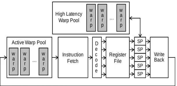
Figure 2.1: Single streaming multiprocessor architecture composed of multiple stream proces-sors.
are composed of multiple Stream Processors (SPs) [48] that execute scalar threads. SPs are
primarily ALUs and do not have individual register files or instruction fetch units; instead, SPs
receive instructions and data from a single shared instruction fetch unit and register file. The
SM register file is highly banked to allow for multiple simultaneous accesses by SPs. Each SM
also contains two thread queues to manage the threads assigned to it (see Figure2.1).
For all SPs inside of an SM to share a instruction fetch unit efficiently, threads running
within a processor group must execute the same instruction, and register names are manipulated
to access different data on all the SPs. Individual threads are then grouped into warps [48] at
application launch and remain together throughout their lifetime. The number of threads in a
warp can be a multiple of the number of SPs in a SM. All threads in a warp then execute in
lock-step, requiring only one instruction fetch for all threads. Warps are the granularity used
for scheduling inside an SM, where the individual threads of a warp are assigned an individual
SP.
Unlike conventional scalar thread processing, SPs execute one instruction from a warp and
can then switch to another warp on the next cycle. Fast switching is done by using a scheduling
thread queue (with each element organized as warps) and a large register file. The register file
is large enough to accommodate all threads assigned to an SM. The number of registers that
A
for( i=0;
i<thread ID;
i++)
B
C
Exit Loop
a) Example Program
A
i=0
B
B
i=1
B
i=3
C
B
i=2
Time
b) PDOM Looping
efficiency for single warp
Active Thread
Idle Thread
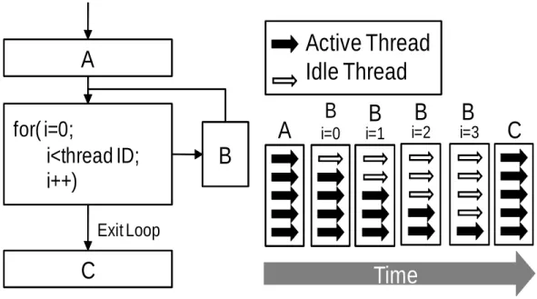
Figure 2.2: PDOM branching efficiency for a single warp performing a looping operation.
threads assigned per SM (the size of the thread queue is also another possible limiting factor).
A warp is fetched from the thread queue after execution of the current warp instruction. Once
a warp has finished data write-back for the fetched instruction, the warp is placed back in
the thread queue. If the current executed instruction requires a high-latency operation before
write-back, the warp is placed into another thread queue. Once the instruction finishes, the
warp is moved back into the scheduling thread queue.
2.2 Thread Control Flow Divergence
To allow for branching instructions, threads within a warp must be allowed to follow
dif-ferent control flow paths while using a single instruction fetch unit. Consequently, all possible
control paths in a warp are executed sequentially and threads not requiring the current control
path do not commit the results of those instructions. To minimize the performance loss of SPs
sitting idle, reconvergence algorithms, such as Immediate Post-Dominator (PDOM) [28], are
an example for a simple data dependent looping operation (similar to the one presented by
Fung et al. in [23] for instruction branching), and how PDOM results in multiple idle
stream-ing processors. The example application in Figure 2.2a only has two control paths for the
loop (running B again or executing C) and a single thread convergence location (C). PDOM
first executes the first control path for B until there are no more threads requiring this path
(Figure2.2b). The next control path is executing C, where all threads would be enabled, since
C is the convergence location for all the threads in the warp. If the runtime for B is much
larger then for both A and C, the looping operation would only be 50% efficient since only half
of the SPs would be used on average.
Consequently, applications that require complex control flow or long-running diverging
branches can have decreased processor efficiency, due to the idle SPs that are completing all
control flow paths before the warp can converge from the diverging paths. Figure 2.3, plotted
using AerialVision [5], illustrates how many streaming processors are running idle per clock
for executing a highly divergent ray-tracing application. This plot categorizes a warp into 10
different categories based on the number of threads in a warps that are not idle. Category
W29:32 is the number of warps that have 29 to 32 active threads in the warp. Category W1:4
indicate that there are only 1 to 4 active threads and the remanding are idle due to branching.
Two types of control flow instructions are implemented in SIMT architectures: predicated
instructions and jump instructions. Predicated instructions [12] are only executed if the
predi-cation register is set. With predipredi-cation, no stack modifipredi-cations are required (unless a predicated
jump instruction is executed) since all threads advance to the same next PC whether or not
they executed the predicated instruction. This work does not attempt to improve performance
for predicated instructions since predicated instructions are less common and larger predicated
code blocks could be re-written to use jump instructions. Jump instructions alone are no
con-cern since all threads executing a jump instruction move to the jump target resulting in no
thread control flow divergence. Thread divergence in a warp only occur when a predicated
jump instruction is executed. In this scenario, each thread can have different predicate register
values that can result in some of the threads executing the jump and others skipping the jump
Clock Cycles
A
c
ti
v
e
T
h
re
a
d
W
a
rp
s
0
300,000
0
1,000
Traditional Branching Hardware
Figure 2.3: Divergence breakdown for warps using traditional SIMT branching methods for
the conference benchmark. Higher values in the key represent more threads that are active
within a warp. This figure was created using AerialVision [5].
Improving the under-utilization of SPs can have a dramatic effect on the performance of
an application, without the need of additional processing power. As previously mentioned, in
our observation of branching performance, scalar thread branching only decreases performance
when threads in a warp follow different control paths. If all threads in a warp follow the same
control flow, there is no performance loss. Additionally, two different warps can have diverging
CHAPTER 3. Literature Review
3.1 GPGPU-Computing
General-Purpose Computing on Graphics Processing Units (GPGPU) allowed parallel
ap-plications to be executed on graphics processors that often had a higher GFLOPS than modern
time CPUs (See Figure 3.1). While early 3D graphics processing hardware were implemented
entirely in fixed logic (such as the one described in AppendixB), graphics design continue
im-proving performance by leveraging the abundant amount of parallelism in graphics algorithms.
As processing technologies continued to shrink, additional parallel processing logic is added to
GPUs. To improve the visual quality of rendered images, programmable shaders were
even-tually added to the rendering pipeline [37]. As the GPU programmable shaders continued to
advance, several high level programming languages were created for the intent of being used
for rendering computer graphics [21, 33]. As the GFLOP difference between CPUs and GPUs
continued to grow (see Figure3.1) and the GPU pipeline continually added programmable
ca-pabilities, developers started porting general-purpose computations to the graphics rendering
pipeline [51]. Initially GPGPU developers were required to map their general purpose
appli-cations to one of the common graphics rendering APIs, either OpenGL [62] or DirectX. Later,
several APIs such as BrookGPU [13, 14] and Lib Sh [31] were developed that allowed GPGPU
developers to port their applications to these APIs designed to run on the GPU pipeline but
not requiring the graphics APIs. Today GPU venders support multiple APIs designed for
both graphics (OpenGL and DirectX) and GPGPU computing (NVIDIA CUDA [48], ATI
Streams [6] and OpenCL [42]).
While GPU computing is increasing in popularity, graphics processing still influences the
Figure 3.1: NVIDIA’s GPU Theoretical GFLOP performance compared to Intel CPU’s. This figure is from NVIDIA’s CUDA C Programming Guide [50].
flow is processed. Rendering shaders that run on the GPU programmable shaders started off
with only a few instructions that did not require much control flow (initial shaders supported
none). As rendering shaders grew in complexity, branching support was improved, however
today’s shaders still contain less complex control flow than GPU computing applications.
Con-sequentially, GPU computing uses the same branching methods as GPU shaders, where the
branching performance is not a large concern in graphics shaders.
3.2 Warp Control Flow
Improving wide SIMT processor efficiency for complex control flow has been approached
from both hardware and software perspectives. Persistent threads [1] is a software scheduling
algorithm specifically for ray tracing applications. This approach uses just enough threads to
keep the machine full, and allows warps to focus on a single section of the entire algorithm.
queues to pass data between warps. Warps are then executed in a loop operation for reading
work from a queue, performing computations, and then writing back to another queue or
device memory. Once the work queues are all empty, the threads then exit. Divergent control
flow is reduced by allowing threads in a warp to write to different work queues. Since this
is entirely a software solution, this algorithm can be applied to current and future hardware
that supports the required memory transaction instructions. To prevent concurrency errors
during work queue translations from the large number of parallel threads running at a time,
atomic instructions are required. Atomic instructions result in higher instruction latencies to
serialize the instructions operating on the same data. Scheduling of warps is also left up to
the developer, resulting in complex scheduling code for workload balancing, or simple methods
that can result in an unbalanced distribution.
Hardware support for SIMT branching has grown in complexity as machines continue to
advance to support wider application scopes. Early SIMT machines supported branching using
mode bits [12] (also called predicated masks). Mode bits would disable the results for specific
threads from being written back, effectively disabling the processor. This method results in
every instruction being executed and processors are turned off accordingly. Modern day
pro-cessors still implement mode bits for short branching instructions; however it does not support
diverging control flow.
Dynamic warp formation [23] allows for warps to be modified to contain different threads
during runtime. Processor cores have multiple warps assigned at application launch and only
a few can be executed through the pipeline at a given time. As warps exit the pipeline back
into the warp pool, threads are separated based on their next PC and placed into new warps.
Warp metadata is then expanded to keep track of which threads are in a warp, so that register
translation methods can still function correctly. Threads can be organized into warps using
two methods. The first requires that threads cannot change the SP to which it was
origi-nally assigned. This method needs minimal hardware support, but limits thread flexibility.
The second method adds a cross-bar network to all SPs to allow register values to be passed.
While this adds hardware complexity, threads can be assigned to any warp that has a thread
modifi-cations. Thread Block Compaction [22] further expands Dynamic Warp Formation by only
re-organizing threads into warps at diverging branch locations. Thread Block Compaction also
uses the PDOM location data to re-organize threads back into the original warps for improved
memory operations.
Dynamic Warp Subdivision [41] allows warps that contain stack entries that could be
ex-ecuted in parallel to temporarily separate into two warps. Each warp is composed of a single
control flow path that is scheduled independently of the other warps (where with PDOM, each
control flow path is scheduled sequentially). Subdivided warps are re-converged at the PDOM
locations to maintain optimal processor utilization. Since subdivided warps are executed on
the same SM, performance improvements can only result for applications where the scheduler
runs out of available warps to schedule (either due to long latency instructions or limited work)
and for applications that result in diverging branches that can run in parallel.
Re-convergence at thread frontiers [18] attempts to re-converge divergent threads in a warp
before the Immediate Post-Dominator Locations. Unstructured control flow code can often
result in divergent threads running the same basic block instructions before their Immediate
Post-Dominator point. Re-convergence at thread frontier allows for these threads to be
re-converged at these basic blocks, by prioritizing the scheduling of basic blocks and identifying
control flow paths that could potentially intersect before the PDOM location. Re-converging
threads before the PDOM location reduces the total number of executed instructions and
scheduled warps.
Decreasing warp size [36] while maintaining the number of thread lane processors also
im-proves processor utilization for highly divergent applications. This method potentially imim-proves
performance for applications consisting of large amounts of thread divergence since the number
of threads in a warp is smaller resulting in fewer threads potentially diverging. Applications
with small amounts of divergent control flow will see little performance gains and hardware
implementation to maintain the same IPC results in additional warp scheduling hardware.
Large Warps and Two-Level Warp Scheduling [43] improves branching performance by
increasing the number of threads in a warp such that it is significantly larger than the number
thread’s control flow path allowing for threads to be grouped for improved processor utilization.
Programming models for GPUs have focused on graphics rendering [62] and general-purpose
computations [48, 6]. Graphics rendering programming models use the concept of a pipeline.
While different pipeline stages can be programmable using custom kernels, additional pipeline
stages cannot be added and the data movement between stages is fixed. Furthermore,
im-plementation of the fixed logic hardware components is proprietary and fixed. Programmable
graphics pipelines is supported in GRAMPS [67], where user-defined pipeline stages
(imple-mented using kernels) pass data between stages using queues. However, underlying
CHAPTER 4. Hyper-threaded SIMT Cores
The first proposed software/hardware branching solution focuses on extending the
capabil-ities of the Immediate Post-Dominator (PDOM) branching solution to allow for SIMT
Hyper-threading architecture. Hyper-Hyper-threading allows for parallel execution of different control paths
from a single warp. Application developers can configure how the parallel execution of
differ-ent control paths are performed through modifying data fields in the warp meta-data. Since
this method is an expansion to PDOM, static allocation of threads into warps is maintained,
making it a good target for diverging branches that are not long or are deeply nested in the
control flow graph.
Hyper-threading [40] creates multiple parallel processors out of a single processor core.
While conventional hyper-threading uses different execution data paths to mimic more
proces-sors, this approach divides the individual thread processing lanes. This creates multiple SIMT
processors of varying warp-sizes from a single SIMT core. Using a single warp to schedule
paral-lel threads for hyper-threading, no conflicts will occur between processing lanes when forming
SIMT hyper-threading processors (See figure 4.1c). Conventional hyper-threading using the
SIMT thread processor’s execution pipelines can also be implemented along with this proposed
hyper-threading architecture.
To determine how to divide the individual thread lane processors for hyper-threading, the
per-warp stack reconvergence table is extended. I present three algorithms for managing the
stack entries, as this could be customized for specific applications. The first presented algorithm
is used to schedule stack entries with no thread conflicts with other stack entries. With this
method, only diverging control flow produced from if-else or case statements will utilize the
hyper-threading architecture. The second approach spatially divides all thread lane processors
Scheduler Instruction Fetch: A T h re a d L a n e 0 Write Back T h re a d L a n e 1 T h re a d L a n e 2 T h re a d L a n e 3 Warps Warp 0 Warp 1 Warp 2 Threads PC
A A A
A
(a) SIMT Scheduler Instruction Fetch: A T h re a d L a n e 0 Write Back T h re a d L a n e 3 Warps Warp 0 Warp 1 Warp 2 Threads PCB B
A
A
(b) Divergence Scheduler Instruction Fetch:A
,B
T h re a d L a n e 0 Write Back T h re a d L a n e 3 Warps Warp 0 Warp 1 Warp 2 T h re a d L a n e 1 T h re a d L a n e 2 Threads PCB B
A
A
(c) HyperThreadFigure 4.1: Single-Instruction Multiple-Thread Architecture for processing a warp. a) No thread Divergence. b) Thread divergence. c) Our 2 way hyper-threading architecture.
similar to reducing the warp size while keeping the processor core count the same. The only
exception is the warp size is not decreased. For a warp to finish, all spatially divided thread
lanes must finish before a warp is completed. The final approach attempts to maximize the
thread lane utilization by picking two instructions in the warp stack that will result in the best
performance.
4.1 Warp Divergence
A limitation of running threads in warps is that each thread in a given warp will only
B C A D PDOM Stack ^ƚĂĐŬĞƉƚŚ W ĐƚŝǀĞdŚƌĞĂĚƐ WKD Ϭ ϭϭϭϭ Ͳ ϭ ϭϬϬϬ Ϯ Ϭϭϭϭ (a) If-Else F E G PDOM Stack ^ƚĂĐŬĞƉƚŚ W ĐƚŝǀĞdŚƌĞĂĚƐ WKD Ϭ ' ϭϭϭϭ Ͳ ϭ & ϭϬϬϬ ' (b) If I H J PDOM Stack 1,2 ^ƚĂĐŬĞƉƚŚ W ĐƚŝǀĞdŚƌĞĂĚƐ WKD Ϭ : ϭϭϭϭ Ͳ ϭ / ϭϭϭϬ : ^ƚĂĐŬĞƉƚŚ W ĐƚŝǀĞdŚƌĞĂĚƐ WKD Ϭ : ϭϭϭϭ Ͳ ϭ / ϭϬϬϬ : Stack 1 Stack 2 (c) Loop
Figure 4.2: Different categories of warp divergence. (a) results in two different control flow paths before all threads reconverge at ‘D’. (b) Only a single diverging control flow is required before threads reconverge at ‘G’. (c) A looping operation where one iteration has 3 threads active and a later iteration has 1 thread. Similar to (b), only one diverging control flow is created before reconvergence at ‘J’.
runs longer than all others, the other threads, while potentially complete, continue to consume
idle execution cycles. The best performance time for all threads in a warp is equal to or
greater than the time to processes the longest running thread in the warp. Figure 4.2 shows
different categories of predicated jump instructions that result in branch divergence and how
each category effects the processor thread lane utilization. Figure4.2ashows a divergence that
results in two control flow paths before the paths reconverge (such as code generated from if-else
statements). In this case, three stack entries are used where the bottom stack entry represents
the reconvergence point and the other two entries represent the two control flow paths. Both
control flow paths are executed resulting in every thread lane going unutilized at some point
during the execution of this diverging statement. The second category is shown in figure 4.2b
where one of the diverging control flow paths jumps straight to the reconvergence point such
as a single if statement. In this case, only the threads that jump to the reconvergence point go
idle and wait for the other control flow path to reach the reconvergence point. Only two stack
entries are needed, one for the reconvergence point and the other for the single diverged control
flow path. The final case is a looping category shown in figure 4.2c. Divergent branching of
B
A
E
D
PDOM PDOMC
for( i = 0; i <= threadID; i++)
for( i = 0; i <= (3 - threadID); i++)
Figure 4.3: Example application containing multiple diverging loops where threads run a varying number of iterations per loops. In PDOM, the second loop can only be run after all threads finish the first loop. Using Hyper-threading, threads that finish the first loop can begin executing the second loop before all threads finish the first loop.
using thread specific data. While this case is similar to figure 4.2bwhere one of the branching
paths results in the reconvergence point and the other is a separate control flow path, the
number of times the separate control flow path is executed may vary between threads. The
thread processing lane utilization can also decrease during every loop iteration. Only when the
last thread exits out of the loop will all threads be able to continue.
4.1.1 Parallel Execution of Diverged Warps
Accelerating if-else diverging branches (Figure 4.2a) can be done by scheduling both
di-verging control flow paths in parallel. If the two control flow paths have different lengths,
then both are run in parallel until they reach the reconvergence point. Once one path reaches
the reconvergence point, the threads go idle until the other path reconverges. The expected
performance gain for this is max(pathA, pathB)/(pathA+pathB).
Increasing performance for if statements and loop diverging branch categories cannot be
done for just a single diverging point in an application. Running parallel control flow paths
that the alternative path will still execute. To accelerate these diverging categories, multiple
branching operations must be present. In figure4.3there are two sequential looping operations
where the number of loop iterations are different for the same thread between the two loops.
In conventional SIMT scheduling the time required to finish both loops will be the sum of
the time that the longest thread took in loop one and the longest time a thread took in loop
two. In this example the longest time in loop one is from thread ID 3 of 10 iterations and
for loop two it is thread ID 0 of 10 iterations. Allowing threads to execute in parallel past
their reconvergence point may be beneficial if there are additional branching statements. In
our example from figure 4.3, allowing thread ID 0, that requires the longest time in loop 2, to
start in loop 2 while other threads are in loop 1 is possible since thread 0 is able to exit out of
loop 1 before the other threads. This results in thread 0 not having to wait for all threads to
finish loop 1.
In both cases the best performance time possible for a warp is still limited to the time
required to process the longest running thread. These parallel execution methods for diverging
warps are designed to get warp processing time closer to the best case warp performance
time. This is done by reducing the time that the longest running thread is idle due to branch
divergences from other threads in the warp that run longer than the longest running thread in
a specific branch. Warps with execution time already equal to the time required to process the
longest thread will not see any performance improvement.
4.2 SIMT Hyper-Threading Architecture
Hyper-threading [40] allows for a single processor core to mimic a multi-core processor by
allowing multiple threads to use different processor core components, such as a floating point
unit and integer pipeline. To support multiple threads being executed in parallel, additional
hardware is implemented to add capabilities to fetch multiple instructions and perform the
necessary register access. In this implementation of SIMT hyper-threading, the individual
thread processing lanes are the processor core components that are intermixed to create multiple
virtual parallel SIMT processors from a single core. Additional hardware resources are required
PC Active Threads (one bit per thread) SIMT
͗
PC 1 PC 2 Active Threads (two bits per thread) Hyper-Threading of 2
͗
PC 1 … PC n Active Threads (log2(n) bits per thread) Hyper-Threading of n
͗
Figure 4.4: Warp meta-data fields for both PDOM and hyper-threading warps. Conventional SIMT warps only requiring knowing a single instruction PC and what threads out of the warp requiring executing this PC. For hyper-threaded warps, multiple instruction PCs are required in addition to expanding the active thread mask to indicate which threads are active and which instruction PC is required.
The TLP scheduler for selecting warps to execute is not changed however the data structure
used to represent warp meta-data is expanded to allow additional PC fields as well as the active
thread field such that each thread has the required bit representation to select from the available
PCs. The expanded warp meta-data is shown in Figure 4.4. The number of virtual processors
that hyper-threading is able to create is implementation dependent and can range from 2 up
to the warp size. With increasing hyper-threading virtual processor count, the warp meta-data
will grow to store all the required PCs and active thread masks.
The warp meta-data retrieved from warp scheduling contains all the required PCs to be
fetched. The port size for the Instruction Cache is increased to support the maximum number
of instructions that may need to be fetched. A cache miss for any of the instructions results in
all remaining PCs waiting for the cache miss to be resolved. Once all instructions are fetched,
the individual thread processing lanes select which of the instructions to execute using a mux
with the selecting signal being the warp meta-data active thread mask as shown in Figure4.5.
Individual processing lanes executing shorter latency instructions must wait for all processing
lanes to finish before the write-back pipeline stage. A waiting pool is used for storing threads
that finish before others.
Setting the PCs and active thread masks field in the warp meta-data for diverging
instruc-tions is performed using custom instrucinstruc-tions that are inserted by a just-in-time compiler. These
instructions update the per-warp stack and also the PCs warp meta-data when divergence
Waiting Pool Available Warps … Warp 0:A B 1, 2, 2, 1 Warp 1:A - 1, 1, 1, 1 Warp 1:A B 1, 1, 0, 2 Scheduler: AB 1, 2, 2, 1 Instruction Cache Instructions add %r3,%r4,%r5 ld %r1, [%r5]; PC 1 PC 2 Active Mask Warp Meta-Data Write Back T h re a d L a n e 0 T h re a d L a n e 1 T h re a d L a n e 2 T h re a d L a n e 3
Figure 4.5: SIMT 2 way hyper-threading architecture resulting in two virtual processors.
stack based algorithms to be tested. Typicaly instructions are inserted at all possible points of
control flow divergence and reconvergence.
4.2.1 Stack Manipulation Algorithms
In this section I present three hyper-threading per-warp stack modification algorithms.
These algorithms are not necessarily intended to reflect ideal solutions, as more tailored
al-gorithms can be generated for specific applications to further improve performance. Instead,
the three presented below are designed for general applications and to study the performance
effects across various methods.
4.2.1.1 Parallel Stack Entries
This stack modification algorithm uses hyper-threading to schedule only stack entries that
Algorithm 1 Parallel Stack Scheduling Require: Depth = Stack Depth
Require: Stack = Stack Location
Require: NumSch = Hyper-Threading Size
Require: MetaData = Warp Meta-Data
1: # Schedule top stack entry
2: MetaData.PC[1]←stack[Depth].PC
3: MetaData.ActiveMask←stack[Depth].ActiveMask
4: # Search through rest of stack for non-conflicting entries
5: numScheduled←1
6: index ←Depth−1
7: scheduledMask←stack[Depth].ActiveMask
8: while (numScheduled≤NumSch) AND (index≥0)do
9: if (stack[index].ActiveMask & !scheduledMask) = 0then
10: # Found stack entry with no thread conflicts
11: # Add entry to warp meta-Data for scheduling
12: numScheduled←numScheduled+1 13: MetaData.PC[numScheduled]←stack[index].PC 14: MetaData.ActiveMask|= stack[index].ActiveMask 15: scheduledMask|= stack[index].ActiveMask 16: end if 17: end while
diverged control flow paths that result in parallel paths before the PDOM point will be
sched-uled. Manipulating the stack entries is done using the same algorithm used for PDOM where
two additional stack entries are added to the stack. After each stack modification a scheduling
algorithm is called to determine which stack entries to schedule. The algorithm to determine
which stack entries to schedule is shown in Algorithm1and first schedules the top stack entry.
After that it searches through the rest of the stack to find any other entries that could also
be scheduled. Bit masking operations are applied to check for non-conflicting threads in all
stack entries. If a valid stack entry is found, the warp meta-data is updated to include the
required information. In this scheduling method PDOM reconvergence points are still used to
reconverge thread paths. Thread synchronization require no additional implementation since
synchronization points requires all threads in a warp to be converged, which is taken care of
using conventional PDOM.
4.2.1.2 Work Ahead
To potentially accelerate branching categories in Figure 4.2b and 4.2c, threads must be
^ƚĂĐŬĞƉƚŚ W ĐƚŝǀĞdŚƌĞĂĚƐ WKD Ϭ ϭϭϭϭ Ͳ ϭ ϭϭϬϬ
B
A
D
E
P D O M P D O MC
^ƚĂĐŬĞƉƚŚ W ĐƚŝǀĞdŚƌĞĂĚƐ WKD Ϭ ϭϭϭϭ Ͳ ϭ нϭ ϬϬϭϭ Ϯ ϭϭϬϬ ϯ нϭ ϭϭϬϬBefore Work Ahead After Work Ahead
Figure 4.6: Sample stack modification for allowing threads at a PDOM point to work ahead. The PDOM stack entry (depth 0) is split into three new stack entries: 1) For the next PDOM to reconverge all threads back together. 2) Stack entry for threads working ahead. 3) Stack entry to progress threads currently not at PDOM point to progress to the next PDOM point.
point must be split into three stack entries because some of the threads in this entry are
dependent on stack entries further down the stack (see figure 4.6). Determining the
non-dependent threads is done using bit masking operations and traversing all stack entries between
this entry and the top of the stack. The lower of the three stack entries contains the original
active thread mask and the PC of the next PDOM point from the current PC. The next stack
entry is for all the threads that are allowed to work ahead and has a PDOM value set to the
next PDOM point. The third stack entry added is the original PDOM stack entry except the
active thread mask is reduced to only the threads that could not work ahead due to other
stack entry dependencies. By creating the third lower level stack entry for the next PDOM
reconvergence point, we allow a method for threads working ahead to reconverge with the
original stack entries in the case that original threads left behind eventually catch up to these
threads.
To determine which PDOM point to work ahead for in the case there are more options than
hyper-threaded processors, each PDOM point is given a priority. Priority is computed off-line
during compile time and is set based on the shortest path to a looping jump instruction. In
loop. While this method favors looping operations over other diverging operations, loops are
given the highest likelihood of acceleration since they are performed multiple times compared
to other branching methods.
Loop Lapping is a common source of performance gain for this method and occurs when
a thread exits a loop and while working ahead enters back into the same looping operation.
To improve the performance when loop lapping occurs, since threads that have worked ahead
are in a different stack entry than the other threads that are all in the same loop, the stack
modification algorithms (when triggered by a diverging instruction or threads reaching PDOM
points) scans all entries to determine if multiple stack entries could be merged together in the
warp meta-data. By merging them in the warp meta-data, similar stack entries only consume
a single hyper-threaded processor.
4.2.1.3 Spatial Subdivision
Spatial subdivision stack modification algorithm attempts to mimic smaller warp sizes by
dividing the threads into smaller equal sized groups at the first diverging point (Figure 4.7).
The new group sizes are determined by the number of hyper-threading virtual cores that can be
created. For example, a 2-way hyper-threading with 32 thread per-warp will divide the stack
into two 16-threads per group. Each group then behaves similarly to PDOM where each of
the top stack entries for each group is scheduled. SIMT hyper-threading allows for the smaller
thread groups to run in parallel, however the overall runtime for the entire warp is still limited
to the longest running thread in the warp. To handle thread synchronization, all threads must
be reconverged. Before a thread executes a thread syncronization instruction, the warp’s stack
is modified such that the stack entry at level 0 has the PC for the synchronization point (the
stack entry at level zero already contains the list of all active threads in the warp). All other
stack entries for this group are then removed from the stack. Only when the stack entry is at
^ƚĂĐŬĞƉƚŚ W
ĐƚŝǀĞdŚƌĞĂĚƐ
WKD
Ϭ
ϭϭϭϭϭϭϭϭ
Ͳ
ϭ
ϭϭϭϭϬϬϬϬ
Ϯ
ϭϭϬϭϬϬϬϬ
ϯ
Ͳ
ϰ
Ͳ
ϱ
Ͳ
ϲ
Ͳ
ϳ
Ͳ
ϴ
ϬϬϬϬϭϭϭϭ
ϵ
Ͳ
Ͳ
Ͳ
PDOM Stack
for Group 1
PDOM Stack
for Group 2
Fixed Offset
Threads for Group 1 Threads for Group 2Scheduled
stack entry for
hyper-threaded
processor 1
Scheduled
stack entry for
hyper-threaded
processor 2
Figure 4.7: Warp stack layout used for spatial subdivision stack management algorithm. This layout is designed to mimic smaller warps using hyper-threading.
CHAPTER 5. Dynamic µ-Kernel Architecture
Our second proposed software/hardware branching solution is targeted for long diverging
control flow paths. This solution breaks the static allocation of threads into warps to potentially
achieve higher processor utilization then possible with the static thread allocation. While
re-grouping thread allocations during runtime results in a slight processing overhead (making it
not feasible for short branches), certain branching behaviors can see a large improvement in
processor efficiency.
Our dynamicµ-kernel implementation is broken down into two components. The first part
allows SPs to create new processing threads. The second part takes new threads and creates
new warps that will not result in large divergent control paths. The process of creating threads
at runtime and forming new warps is outlined in Figure 5.1. Threads are able to initiate the
creation of threads inside an SP using a new instruction which we call spawn. The SM then
groups the new threads with previously created threads that share the same targeted µ-kernel
in the partial warp pool. Once enough threads are grouped to form a new warp, the warp
is placed into a new warp FIFO and waits to be scheduled for execution. When a currently
scheduled warp finishes, a new warp from the warp FIFO is issued using the same resources as
the finished warp and placed into the active warp pool.
In addition to the SM hardware for issuing new threads, data must be passed from the
parent thread to the newly spawned child thread that is intended to continue the work of
the parent thread. Data required for the spawned threads cannot be passed using registers
since the new thread is likely to be assigned a different SP then its parent. Depending on
the applications requirement of persistent memory between µ-kernels, register states can be
saved to either on-chip shared memory or off-chip global memory. When a thread is created at
Warp
Warp
Warp
Active
Warp Pool
SPs
New
Threads
Partial Warp Pool
New Warp FIFO
Completed Warp
F
in
is
h
No
Yes
Figure 5.1: Dynamic thread creation hardware overview. New threads created by the SPs are placed into new warps waiting in the partial warp pool. Once enough threads have been created to complete a warp, the warp can replace an existing warp that has finished.
data.
5.1 Memory Organization
Similar to NVIDIA CUDA [48] supported architectures, the available memory spaces for
a thread consists of registers, shared memory, local thread memory, global device memory,
constant memory, texture memory, and a new memory space calledspawn memory. Registers
and shared memory are located on-chip and are tied to an SM. Local thread memory is stored
in off-chip device memory. Local thread memory is reserved for register overflow to reduce
register counts for kernels and also for any intermediate data storage that is too large for
on-chip memory. Constant memory and texture memory also use device memory and are used
similar to local memory except that they are read-only and can be cached. Global device
memory is off-chip and is shared across all SMs, and can also be allocated and accessed by a
Spawn memory may be implemented in on-chip memory inside an SM or device memory.
The memory space is used for two purposes: storing the data to be passed between threads and
storing partial warps during warp formation (see Chapter5.3). This memory space is allocated
at kernel launch time since the size requirements can be computed off-line and are constant
throughout application execution.
5.1.1 Thread Usage of Spawn Memory
The first section of this memory space is for storing data to be passed between threads.
The allocation size is computed by the size of the data structure used for passed data between
threads, multiplied by the number of threads that can be assigned to an SM. Since the size
of the data structure may vary depending on what µ-kernel is being called, the largest data
structure is used for the computation. This also requires that the µ-kernels must be defined
before the application is executed. Individual threads in an SM are then assigned a region of
this memory space.
The method that threads access their spawn memory space depends on how the thread is
cre-ated and when it is scheduled. However, all threads use a special register calledspawnMemAddr
to determine the spawn memory address. Threads initially created and scheduled at application
launch have theirspawnMemAddr set to a unique address inside the spawn memory using the
equationSpawnM emoryBaseAddress+threadID∗sizeof(dataT oBeP assedBetweenT hreads). Dynamically created threads are provided a memory pointer in thespawnMemAddr when
sched-uled that is used to obtain the appropriate spawn memory address (see Chapter 5.4). Threads
that were created at application launch but were not able to be scheduled due to resource
availability require a spawn memory address that has been freed by a thread, made available
when a thread exits from the last µ-kernel.
Data in the spawn memory space is what is passed between a parent and child thread. If a
thread is creating a child, the parent thread will store its current state in the spawn memory
before calling the spawn instruction. If the thread is a child, the spawn memory space is used to
retrieve data from its parent thread. Child threads can reuse the same spawn memory address
5.1.2 Partial Warp Formation
The second half of the spawn memory space is for storing dynamic threads during warp
formation. The hardware components for creating new warps require consecutive memory
addresses to store the meta-data of individual threads belonging to a new warp. The number
of consecutive memory address is equal to the number of threads in a warp. The minimal size
required for this memory is a function of the number of threads that can be assigned to an
SM, the number of threads per-warp and the number of µ-kernels (size = N umT hreads+
(SpawnLocations−1)∗W arpSize). The size allocated in memory is doubled to prevent new
threads meta-data from clobbering active threads. The spawn memory used for passing data
between threads does not need to be doubled, since registers can be used to save original data
when reusing the memory space for creating a child thread.
5.2 Spawn Instruction
Spawn instructions take two parameters: an assembly code label (converted by the
assem-bler to the Program Counter (PC) value), used to indicate the new thread’s µ-kernel and a
register that contains the memory pointer to the thread’s spawn memory space. The spawn
function performs two key functions. First, it updates the warp creation hardware used to
as-sign the new threads into warps. Second, it performs a memory write operation that is required
by the warp creation hardware to save the thread’s meta-data.
5.3 Warp Formation
Figure 5.2 shows the architecture for the spawn instruction for an SM. The first operation
performed is thread classification where new threads are placed into warps. The PC value of
the spawn instruction will be the same value for all threads executing the spawn instruction.
The value is the same for all instructions since the PC value is statically compiled into the
instruction and all instructions in a warp execute in lock-step. The PC is used in a look-up
table (LUT) to determine the address in the spawn memory space where similar threads are
H
PC PC PC Addr 1 Addr 1 Addr 1PC-Warp
>hd
Address Thread 0 Address Thread 1 Address Thread n Addr 2 Addr 2 Addr 2 Cnt Cnt CntNew Addr. Register
Warp Spawn Instruction
Thread ID Active Thread (1 bit) PC Memory Pointer 0 1 0x01f250 0x5f230 1 0 0x60128 n 1 0x52b30 Summation
н
н
н
Write Data Thread 0 Write Data Thread 1 Write Data Thread n
Store Instruction Creation
Thread Classification
Figure 5.2: Architecture for the spawn instruction. Dynamically created threads identify ex-isting threads that will follow the same control path using a look-up table. Once the warp has been identified for the new threads, the memory pointers are stored in memory for later use.
formation concept presented in [23], and provides the mechanism for taking new threads PC
and providing an index to start forming new warps. The LUT is an on-chip memory organized
as a fully associated cache where the number of entries is equal to the number of supported
µ-kernels. The content of our LUT is different from that of [23]: two memory addresses and one
counter variable are stored for each line in the LUT. The counter keeps track of the number of
threads already contained in the partially created warp. The first memory address is the spawn
memory address where the current warp is being created. The second memory address is the
overflow address used for creating the next warp for the same PC. A single spawn instruction
may result in more threads being created for a µ-kernel then the current warp being formed
![Figure 3.1: NVIDIA’s GPU Theoretical GFLOP performance compared to Intel CPU’s. This figure is from NVIDIA’s CUDA C Programming Guide [50].](https://thumb-us.123doks.com/thumbv2/123dok_us/9324317.2810957/26.918.188.725.122.548/figure-nvidia-theoretical-gflop-performance-compared-nvidia-programming.webp)