This item was submitted to Loughborough’s Institutional Repository (https://dspace.lboro.ac.uk/) by the author and is made available under the
following Creative Commons Licence conditions.
For the full text of this licence, please go to:
Remote Control Service System
Architecture and Dynamic Web User
Interface Generation
Xi GUO
Thesis submitted for the degree of Doctor of Philosophy
Loughborough University
Department of Computer Science
II
For Mum and Dad
I would like to thank my supervisor Professor P.W.H. Chung. I appreciate his guidance and support for my research. I also thank him for patiently correcting my papers and thesis.
I would also like to thank Zhining Liao, Moi hoo, Lee Booi, Lin Guan and Sheryl William for their support, understanding and friendship throughout my PhD.
Finally, I would like to thank my parents and my husband Jonathan Hansford for their unconditional support and help for my PhD study. Thank you for always being there for me.
ABSTRACT
According to current development of internet technology, remote control over the internet becomes a heated discussed topic. Some recent technologies such as Service-Oriented Architecture (SOA), web service and ontology offer great opportunity for remote control over the internet and a lot of research has been done into this topic. However, there are still many challenges in architecture design and dynamic user interface generation.
Architectures in this research field lack clear description of controlled machine model as well as related knowledge support. Also, there is little system support further control service development. There is little research on web user interface design for remote control system over the internet. The design of web user interface has the challenge of overcoming the limitations of web technology to satisfactorily support different machines, users and control process requirements.
This work overcomes the limitations on architecture by offering a SOA based design which allows both multiple users and distributed machine access. The system applies a machine model for the description of the machine structure and functions, which help the system to reason about machine components and their relationships with instructions. With a web service based design, different machines can be connected via the system and execute user commands. Using semantic description and ontology based methods the system can automatically retrieve machine information and generate the structure and function descriptions for different machines. Moreover, the system provides services which can support further development in remote control services. The proposed architecture improves on former designs, and offers a flexible architecture for remote control services over the internet.
An intelligent web user interface is also introduced in this work. The design separates the interface data structure from the data representation. Supported by the remote control service development environment, the user interface could adapt to the control sessions. Semantic descriptions are used to describe the page data structure, session context as well as control command. Therefore, control page content can be adapted by the computer to real time control session. At the same time, a session dependent navigation is designed to resolve the problem
II
model and a session dependent semantic data structure, the required machine data can be analysed by the system and categorised according to user’s requirements. Compare with other designs, this service offers a method for web user interface generation for different machines, users and can adapt to different control processes.
The design is demonstrated in five evaluation scenarios aimed at testing different aspects of the system. Evaluation demonstrates the design proposed in this thesis is feasible. It also shows the design can be applied to different areas and adapted to different control related requirements well.
Keywords
Remote control, SOA, Web service, web user interface, ontology, semantic, session dependent navigation, machine model.
III
CONTENTS
ABSTRACT ... I CONTENTS ... III LIST OF FIGURES ... VII LIST OF TABLES ... IX LIST OF ACRONYMS ... X
CHAPTER 1. INTRODUCTION ... 1
1.1. OVERVIEW ... 1
1.2. MOTIVATION ... 1
1.3. PROBLEMS RELATED TO REMOTE CONTROL OVER THE INTERNET ... 3
1.3.1. Remote control system architecture ... 3
1.3.2. Client user interface ... 5
1.4. AIMS OF THE RESEARCH ... 6
1.5. THESIS ORGANISATION ... 7
CHAPTER 2. ENABLING TECHNOLOGIES ... 9
2.1. OVERVIEW ... 9
2.2. SERVICE-ORIENTED ARCHITECTURES (SOA) ... 9
2.3. WEB SERVICE ... 12
2.4. ONTOLOGY ... 16
2.5. SUMMARY AND CONCLUSIONS ... 17
CHAPTER 3. REVIEW OF CURRENT SYSTEM ARCHITECTURES FOR REMOTE CONTROL ... 19
3.1. OVERVIEW ... 19
3.2. ONE-TO- ONE REMOTE CONTROL ... 19
3.3. MANY-TO-ONE REMOTE CONTROL ... 20
3.4. MANY-TO-MANY REMOTE CONTROL ... 22
3.5. SUMMARY AND CONCLUSIONS ... 32
CHAPTER 4. REVIEW OF AUTOMATIC WEB USER INTERFACE GENERATION FOR REMOTE CONTROL ... 34
4.1OVERVIEW ... 34
4.2CHALLENGES FROM WUI DESIGN ... 34
4.3WUI DESIGN RELATED GUIDELINES AND DESIGN MODELS ... 36
4.3.1. General design principles and guidelines for user interface design ... 36
4.3.2. Design models of web applications ... 37
4.4AUTOMATE GENERATION OF MACHINE CONTROL USER INTERFACE ... 38
4.4.1. Automatic generation of control user interface for machines ... 38
4.4.2. Adapting control user interface for different user requirements ... 39
IV
4.5DYNAMIC NAVIGATION FOR WEB USER INTERFACE ... 41
4.6SUMMARY AND CONCLUSIONS ... 42
CHAPTER 5. SYSTEM ARCHITECTURE AND DESIGN ... 44
5.1. OVERVIEW ... 44
5.2. RESEARCH ASSUMPTIONS ... 44
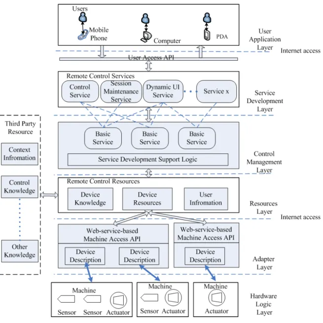
5.3. SYSTEM ARCHITECTURE ... 45
5.3.1. Hardware Logic Layer (HLL) ... 46
5.3.2. Adapter Layer (AL) ... 46
5.3.3. Resource Layer (RL) ... 47
5.3.4. Control Management Layer (CML) ... 47
5.3.5. Service Development Layer (SDL) ... 48
5.3.6. User Application Layer (UAL) ... 48
5.4. MACHINE MODEL ... 49
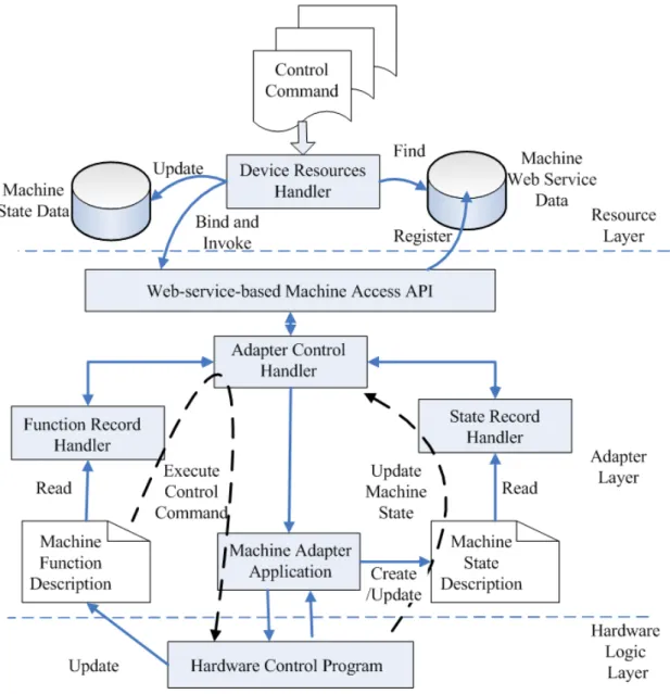
5.5. SEMANTIC DESCRIPTION BASED MACHINE OPERATION ... 53
5.5.1. WMAAPI – APIs for handling semantic information exchange ... 56
5.5.2. MFD – Hardware ability description for controlled machines ... 58
5.5.3. MSD – Semantic description for machine attributes and states ... 60
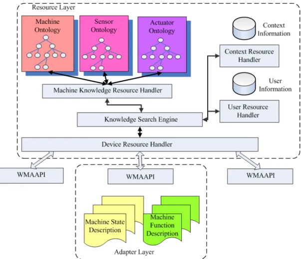
5.6. KNOWLEDGE-BASED MACHINE INFORMATION AUTOMATIC RETRIEVE ... 63
5.7. CONTROL SERVICE DEVELOPMENT ENVIRONMENT ... 67
5.7.1. Basic service support ... 67
5.7.2. Resource support for the services ... 69
5.8. SUMMARY AND CONCLUSIONS ... 69
CHAPTER 6. GENERATION OF INTELLIGENT WEB USER INTERFACE FOR REMOTE CONTROL ... 71
6.1. OVERVIEW ... 71
6.2. CWUI USABILITY FACTORS ... 71
6.3. REMOTE CONTROL SERVICE SUPPORT ... 72
6.4. ARCHITECTURE DESIGN OF WUI ... 74
6.4.1. Collecting requirements that influence WUI design ... 74
6.4.2. CWUI generation ... 76
6.5. SEMANTIC CONTROL RECORDS ... 77
6.5.1. Control Page Logic ... 78
6.5.2. Session Context ... 79
6.5.3. Command Message ... 80
6.6. DYNAMIC CWUI GENERATION PROCESS... 82
6.7. SUMMARY AND CONCLUSIONS ... 83
CHAPTER 7. DYNAMIC GENERATION OF SESSION DEPENDENT NAVIGATION FOR CONTROL INTERFACE ... 85
7.1. OVERVIEW ... 85
7.2. AN EXAMPLE PROBLEM ... 86
7.3. MESSAGE-DRIVEN DATA MODEL ... 88
7.4. SESSION DEPENDENT DATA ... 90
7.5. DYNAMIC NAVIGATION STRUCTURE GENERATION ... 92
V
7.5.2. Generate navigation tree ... 94
7.5.3. Linking navigation and control ... 96
7.6. SUMMARY AND CONCLUSIONS ... 97
CHAPTER 8. EVALUATION ... 99
8.1. OVERVIEW ... 99
8.2. EVALUATION ENVIRONMENT ... 99
8.2.1. Hardware environment ... 99
8.2.2. Knowledge-base and machine simulation ... 100
8.2.3. Demo Software development ... 105
MACHINE CLIENT SIDE PROJECT ... 105
SERVICE SERVER PROJECT ... 105
IWUI SERVICE PROJECT ... 105
8.3. EVALUATION PROCESS ... 109
8.3.1. Machine initialisation ... 109
8.3.2. Client-side evaluation process ... 111
8.3.3. Design of the evaluation scenarios ... 112
8.4. HOISTER HARDWARE CONTROL ... 114
8.5. HOME FACILITY MONITORING AND CONTROL ... 117
8.6. HOTEL EQUIPMENTS MONITORING AND CONTROL ... 124
8.7. FARM DEVICE CONTROL ... 132
8.8. HOSPITAL EQUIPMENT MONITORING AND CONTROL ... 141
8.9. SUMMARY AND CONCLUSIONS ... 149
CHAPTER 9. CONCLUSIONS AND FUTURE WORK ... 151
9.1. CONCLUSIONS ... 151
9.2. CONTRIBUTIONS ... 153
9.3. LIMITATIONS AND FUTURE WORK ... 155
REFERENCE ... 157
APPENDIX ... 167
A. TOP-DOWN NAVIGATION GENERATION CODE USING JAVASCRIPT ... 167
B. ONTOLOGY USED IN THE DEMO ... 170
B.1. Machine ontology (machine.xml) ... 170
B.2. Actuator ontology (actuator.xml) ... 175
B.3. Sensor ontology (sensor.xml) ... 176
C. MACHINE CLIENT PROJECT IMPLEMENTATION ... 178
C.1. MachineAdapterApp.Java ... 178
C.2. AdapterControlHandler.Java ... 185
C.3. MachineWebService.java ... 189
D. SERVICE SERVER PROJECT IMPLEMENTATION ... 192
D.1. MachineKnowledgeHandler.java ... 192
D.2. DeviceReHandler.java ... 204
D.3. MachineControlService.java ... 211
E. IWUI SERVICE PROJECT IMPLEMENTATION ... 213
E.1. ModelReasoner.java ... 213
VI
F. CLASS DIAGRAM FOR THE DEMONSTRATION SOFTWARE ... 230 LIST OF PUBLICATIONS ... 233
VII
LIST OF FIGURES
Figure 2. 1 Collaboration In A Service-Oriented Architecture ... 11
Figure 2. 2 Web Service Architecture ... 14
Figure 3. 1 One-to-one Remote Control Architecture ... 20
Figure 3. 2 Many-to-One Remote Control Architecture ... 21
Figure 3. 3 Many-to-many Remote Control Architecture ... 23
Figure 3. 4 Overview Of The Web-based Remote Control Service System ... 25
Figure 3. 5 Hierarchy Of Remote Control Server ... 26
Figure 3. 6 Conceptual Architecture Of ubiHome Infrastructure ... 27
Figure 3. 7 Detail Architecture Of ubiHome ... 28
Figure 3. 8 Architecture Of The Smart Space Middleware ... 30
Figure 3. 9 Overall Architecture Of The Atlas Architecture ... 31
Figure 5. 1 System Architecture Diagram ... 45
Figure 5. 2 Machine Model Diagram ... 50
Figure 5. 3 The Spectrum Of Control Models ... 51
Figure 5. 4 Machine Model For An Intelligent Light ... 52
Figure 5. 5 Semantic Description Based Machine Operation Diagram ... 54
Figure 5.6 Machine Function Description Example For An Intelligent Light ... 58
Figure 5. 7 Machine State Description Example For An Intelligent Light ... 62
Figure 5. 8 Machine Knowledge Deployed In Resource Layer ... 64
Figure 5. 9 Data Flow In The System During Service Developing ... 66
Figure 6. 1 Remote Control Service Support For IWUI ... 73
Figure 6. 2 IWUI Architecture ... 75
Figure 6. 3 Multi-access Adaption ... 80
Figure 6. 4 Command Message Example ... 81
Figure 6. 5 Data Flow During CWUI Generation ... 82
Figure 7. 1 Controlled Machine Detail List ... 86
Figure 7. 2 Dynamic Navigation Setting Page Example 1 ... 87
Figure 7. 3 Dynamic Navigation Setting Page Example 2 ... 88
Figure 7. 4 States For Message-driven Data Model ... 89
Figure 7. 5 Example Of Data From “Additional Information” Category ... 92
Figure 7. 6 Link From Navigation To Page Content ... 96
Figure 8. 1 Hoister Used For The Evaluation ... 100
Figure 8. 2 Example Of Machine Ontology ... 102
Figure 8. 3 Example Of Machine Location Mapping In XML Format ... 103
Figure 8. 4 Example Of Machine Hardware Simulation Configuration File ... 104
Figure 8. 5 “Machine Initialisation Page” With Main Location Options ... 109
Figure 8. 6 “Machine Initialisation Page” With Sub Location ... 109
Figure 8. 7 New Machine Information Initialisation Page ... 110
Figure 8. 8 “Machine Initialisation Page” Example With Registered Machine ... 111
Figure 8. 9 Client Side WUI Site Map ... 112
Figure 8. 10 “Machine Registration Page” In Hoister Control Evaluation Scenario ... 114
Figure 8. 11 “Function Registration Page” For The Hoister ... 115
Figure 8. 12 “Control Machine Selection Page” In Hoister Control Evaluation Scenario . 115 Figure 8. 13 “Control Panel Page” In Hoister Control Evaluation Scenario ... 116
VIII
Figure 8. 14 “Control Panel Page” In Hoister Control Evaluation Scenario ... 117
Figure 8. 15 “Machine Registration Page” In Home Facility Evaluation Scenario ... 117
Figure 8. 16 “Function Registration Page” Example ... 118
Figure 8. 17 CWUI Example For The “Adjustable Intensity Light” ... 119
Figure 8. 18 CWUI Example For The “Intelligent Light” ... 119
Figure 8. 19 CWUI Example For A Dish Washer ... 120
Figure 8. 20 CWUI Example For A Washing Machine ... 121
Figure 8. 21 CWUI Example For A Window Lock ... 121
Figure 8. 22 CWUI Adaption Example For Window Lock State Change ... 122
Figure 8. 23 CWUI Example For A Heating System ... 122
Figure 8. 24 CWUI Adaption Example For Heating System State Change ... 123
Figure 8. 25 Lights Need To Be Registered In Hotel Evaluation Scenario ... 124
Figure 8. 26 Function Register Example For Manager A ... 125
Figure 8. 27 “Navigation Analysis Page” Example For Manager A ... 125
Figure 8. 28 “Navigation Analysis Page” Update Result For Manager A ... 126
Figure 8. 29 “Control Panel Page” for manager A ... 127
Figure 8. 30 “Control Panel Page” Adaptation Example 1 For Manager A ... 128
Figure 8. 31 “Control Panel Page” Adaptation Example 2 For Manager A ... 128
Figure 8. 32 CWUI when manager A Turned Off All The Lights ... 129
Figure 8. 33 Manager B Only Register The Sensor “Light Intensity Detector” ... 129
Figure 8. 34 “Control Panel Page” For Manager B ... 130
Figure 8. 35 “Control Panel Page” Adaption Example 1 For Manager B ... 131
Figure 8. 36 “Control Panel Page” Adaption Example 2 For Manager B ... 131
Figure 8. 37 Machines Need To Be Controlled In The Farm ... 133
Figure 8. 38 CWUI Example For “Soil Condition Sensor” ... 133
Figure 8. 39 CWUI Example For “Irrigation” ... 134
Figure 8. 40 CWUI Example For “Fertiliser” ... 134
Figure 8. 41 “Alarm Setting Panel” In “Session Dependent Information Setting Page” ... 135
Figure 8. 42 Alarm Set List ... 136
Figure 8. 43 Navigation Analysis Page Result For Farm Evaluation Scenario ... 137
Figure 8. 44 CWUI with “Navigation Bar” And “Alarm Information” For Farm Devices 138 Figure 8. 45 “Alarm Information” Example For Farm Devices ... 138
Figure 8. 46 Example Of “Alarm Information” As Navigation For Farm Devices ... 139
Figure 8. 47 “Alarm Information” Update Example For Farm Devices ... 139
Figure 8. 48 “Alarm Information” Update Result For “Soil Moisture Detector” ... 140
Figure 8. 49 Machines Needing To Be Monitored In The Hospital ... 141
Figure 8. 50 CWUI Example For The “Blood Pressure Monitor” ... 142
Figure 8. 51 CWUI Example For The “Heart Rate Monitor” ... 142
Figure 8. 52 “Additional Information Setting” Panel Example ... 143
Figure 8. 53 User Set Session Dependent Information Example ... 144
Figure 8. 54 “Addition Information List” For New Item “Doctor” ... 145
Figure 8. 55 “Addition Information List” For New Item “Patient Name” ... 146
Figure 8. 56 Navigation Analysis Result For Hospital Equipments ... 147
Figure 8. 57 “Control Panel Page” Example For Hospital Equipments ... 147
Figure 8. 58 “Control Panel Page” Adaption Example For Hospital Equipments ... 148
Figure F. 1 Class Diagram For Machine Client Side Project ... 230
Figure F. 2 Class Diagram For Service Server Project ... 231
IX
LIST OF TABLES
Table 7. 1 Machine State Information Attribute Table ___________________________ 95 Table 8. 1 Hardware Condition For Computer In The Evaluations ________________ 100 Table 8. 2 Package List Of Machine Client Side Project ________________________ 106 Table 8. 3 Package List Of Service Server Project _____________________________ 107 Table 8. 4 Package List Of Iwui Service Project ______________________________ 108
X
LIST OF ACRONYMS
ACH Adapter Control Handler AL Adapter Layer
API Application Programming Interface CML Control Management Layer
COM Component Object Model
CORBA Common Object Request Broker Architecture CPL Control Page Logic
CWUI Control Web User Interface DLL Dynamic-Link Library DOM Document Object Model
DPWS Devices Profile for Web Services DRH Device Resources Handler FRH Function Record Handler GUI Graphical user interface HCP Hardware Control Program HLL Hardware Logic Layer HTTP Hypertext Transfer Protocol IoT Internet of Things
IT Information Technology IWUIC IWUI Controller
IWUIM IWUI Model IWUIV IWUI View
J2EE Java 2 Platform, Enterprise Edition JDOM Java-based document object model JSON JavaScript Object Notation
KSE Knowledge Search Engine MAA Machine Adapter Application MFD Machine Function Description MSD Machine State Description MVC Model-View-Control MWSD Machine Web Service Data OLE Object Linking and Embedding
OOHDM Object-Oriented Hypermedia Design Model OOWS Object-Oriented Web Solution
OPC OLE Process Control OPC UA OPC Unified Architecture
OSGi Open Services Gateway initiative OWL-S Ontology Web Language for Services
XI PUC Personal Universal Controller RMI Remote Method Invoke SDL Service Development Layer SOA Service-Orianted Architecture SOAP Simple Object Access Protocol SRH State Record Handler
UAL User Application Layer
UDDI Universal Description, Discovery and Integration UI User Interface
UIML User Interface Markup Language UPnP Universal Plug and Play
WebML Web Modeling Language
WMAAPI Web-service-based Machine Access API
WSRCSS Web Service-based Remote Control Service System WSDL Web Services Description Language
WSMCG Web-services-based monitoring and control gateway WUI Web User Interface
XML eXtensible Markup Language
CHAPTER 1.
INTRODUCTION
1.1
.
Overview
With the internet, all kinds of information and documents can be accessed by anyone from anywhere without travelling. The potential benefit of remote control and monitoring using the internet is also attracting increasing attention. The idea of using the internet for remote control is not new, but work in this area is still at an early research stage.
This chapter begins with the motivation for the research then highlights some of the problems with current remote control system architectures and client user interface generation. Relating to these problems, the aims of the research are made clear. The final section describes the thesis organisation.
1.2
.
Motivation
Since Leonardo Torres-Quevedo laid down the modern wireless remote-control operation principles in 1901, the development of this technology has not stopped [IEEEGHN, 2007]. In World War I, the German navy used radio controlled motorboats to ram enemy ships [IEEEGHN, 2007; Yang, 2002] and then remote controlled televisions appear [TVhistory, 2001; IEEEGHN, 2007; 1-800-Remotes, 2010]. Today, wireless technologies are used in many fields, such as industrial applications, emergency services, space [IEEEGHN, 2007] and house facilities. Various ways have been used to help people access their appliances like lights, heaters, robots and security systems [Burger and Frieder, 2006; Wang, Liu and Wang, 2006; Ito and Murai, 2007; Kim, et al., 2007].
There are a lot of applications in the real world that could benefit from remote monitoring and control. For example, shift operators may have difficulties with operating a machine due to an unexpected event. An experienced engineer who is located far away from the factory can login remotely and assist with resolving the situation. A person can remotely switch on the heating system at home before leaving work to ensure they return to a warm home. A nurse could
monitor the condition of multiple patients without having to walk around a hospitality ward. The possibilities are endless.
Although various approaches for remote control and monitoring have been proposed, none of them dominates the field. Radio, infrared and ultrasonic signals are used for short distant control [TVhistory, 2001]. With the help of wireless technology, such as Bluetooth [Haartsen, et al., 1998] and Zigbee [ZigBee Alliance, 2011], signals can be sent over longer distances. These technologies help to group the controlled machines in to local networks which can then be connected to a long distance controller via long distance communication technologies such as satellite [David and Jeffrey, 1998]. However, satellite remote control is expensive and is not widely used.
Control and monitoring machines over the internet becomes more feasible than before. First, the internet is widely available and used around the world in offices, factories and home for accessing information and communicating with friends and colleagues. It provides an obvious infrastructure for supporting remote control and easy access to users. Therefore, it is being investigated by a number of researchers [Chen and Luo, 1997; Yang, Tan and Chen, 2002; Dai, Yang and Tan, 2004; Hung, Chen and Lin, 2004; Yang, et al., 2005; Dai, Yang and Knott, 2006; Oltean, Abrudean and Dulau, 2006; Yang, Dai and Knott, 2007]. Also, existing middleware technologies such as OSGi [OSGi Alliance, 2011] (Open Services Gateway initiative), DPWS [OASIS, 2009] (Devices Profile for Web Services), and UPnP [UPnP Forum, 2011] (Universal Plug and Play), as well as industry standards such as OPC [Li and Nakagawa, 2002; OPC Foundation, 2011b] (OLE Process Control) have been improved gradually to make better seamless connection with low level device hardware with high level drive applications. Moreover, many concepts have been discussed recently in order to better integrate devices into IT (Information Technology) systems. For example, “Internet of Things” (IoT) [Gershenfeld, Krikorian and Cohen, 2004; Haller and Karnouskos, 2008] is the idea that future devices will be smart enough to access the internet and potentially be controlled and monitored over the internet. Similar to most of the research on “internet of things”, work in this thesis tries to integrate hardware objects to the internet. Nevertheless, most of current research on “internet of things” focuses on internet-ready embedded devices and the network for devices [Krikorian and Gershenfeld, 2004; Guinard and Trifa, 2009;
Vazquez, et al., 2010], while remote control over the internet discussed in this thesis complement this by focusing on control and monitor mechanism for devices.
Based on current internet technologies, it is relatively easy to build a specified purpose direct remote control system. However, according to current literature review, there is seldom a remote control architecture existing that provides a service for flexibly adding users and machines. Also, there is very little research on web based user interface generation for such a remote control service system. The following section will explain the details of the problems related to remote control over the internet.
1.3
.
Problems related to remote control over the internet
A general problem with the internet is control link security. The internet offers convenient access to resources from anywhere, but at the same time has the risk of exposure to malicious attack. This is a major topic for the internet security research community. Another problem is reliability. Messages transferred across the internet can be lost or corrupted. This is a topic for the communication research community. The maintenance of a control session is more complicated than just recording current state and continuing the control session after the interruption. The influence of the tasks and command sequence should also be considered. However, these problems are already receiving considerable attention. Instead of focusing on these reasonably well established research areas, this thesis focuses on two topics which are important in establishing flexible and convenient control services. The details of these will be explained in the following sections.
1.3.1. Remote control system architecture
The system architecture for remote control is comparable to the structural framework in a house. The design of the remote control system will influence the future expandability of the system and the functions that can be provided. Current architectures [Chen and Luo, 1997; Walsh and Hong, 2001; Yang, Tan and Chen, 2002; Wang, et al., 2003; Dai, Yang and Tan, 2004; Hung, Chen and Lin, 2004; University Of Florida, 2004; Ha, Sohn and Cho, 2005, 2007; Helal, et al., 2005; Yang, et al., 2005; Dai, Yang and Knott, 2006; Oltean, Abrudean and Dulau, 2006; Ha, et al., 2007; Kim, et al., 2007; Yang, Dai and Knott, 2007] have limitations described below:
i. Lack of support for multi-access remote control
A number of remote control system architectures have been proposed [Chen and Luo, 1997; Walsh and Hong, 2001; Yang, Tan and Chen, 2002; Wang, et al., 2003; Dai, Yang and Tan, 2004; Hung, Chen and Lin, 2004; University Of Florida, 2004; Ha, Sohn and Cho, 2005, 2007; Helal, et al., 2005; Yang, et al., 2005; Dai, Yang and Knott, 2006; Oltean, Abrudean and Dulau, 2006; Ha, et al., 2007; Kim, et al., 2007; Yang, Dai and Knott, 2007]. However, these architectures are for developing individual remote control system and do not cater for adding or removing users and machines from the system, i.e. they are not based on a service approach. For an open environment like the internet, these architectures limit future system development and are not adaptable to changing user requirements. For example, some of the control applications allow different users to enter the system but only allow specified machines to be controlled. Some systems only allow machines on a specified area to be controlled, which results in difficulties when introducing new machines outside of the area. This particular issue will be further explained in Chapter 3.
ii. Difficulties in identifying machine structure and functions for multi machine control
Different machines have different actuators and sensors as well as different functions available to a system. Even if the system can establish a control link between the user and the target machines, the system needs to offer an appropriate interface for the user to access the machine information to be able to monitor and control any of the selected devices for any particular control session. This means that it is necessary to facilitate the exchange of appropriate commands and information between any user and any machines that the user has chosen to control. However, the controlled machines can vary and it is difficult to know the structure and functions for the target machines in advance.
iii. Inflexible for new services development
There is no remote control service system that supports the development of innovative services to support the control task. These services can be considered as extendible functionality for remote control ability. For example, services like dynamic control user interface generation need the support of basic control ability. So, these services have to build on the basic control functions. It is difficult to reuse or extend the functionalities if they are tightly coupled to the system. Some researchers have tried to make these abilities into services [University Of Florida, 2004; Helal, et al., 2005; Ha, Sohn and Cho, 2007; Helal, Yang and
Bose, 2007]. However, they have not discussed how to provide a framework for supporting service development for remote control.
1.3.2. Client user interface
Client user interface is a critical issue for almost any system and user interface development is a very resource-intensive task. A good user interface can help users achieve their goals efficiently. For an internet-based remote control system, a user interface needs to be designed to meet user needs and control requirements. This area is generally overlooked by researchers. It is normally assumed that a be-spoke user interface is developed for a control system. However, this would not work if different users can register and logon to control different machines of varying types. The problems in this area are analysed below.
i. Challenges in dynamic generation of user control interfaces
User interface design is a challenging problem when a remote control system allows multi-user access and machines can be added and removed dynamically from the system. For example, the user interface has to be modified when a new type of machine is added to the system. It is a significant problem for the system to offer an appropriate user interface according to the user’s requirements in conjunction with the machines capability. For example, if a nurse needs to monitor the blood pressure and heart rate of fifty patients simultaneously, it would be confusing and inefficient if they were required to view the data for each patient on a separate page. Furthermore, the same nurse may be required to monitor different patients on different wards so the interface has to be designed to display the relevant information and structure them accordingly. Manual design of user interfaces is time consuming and limits the future extensibility of a system. Additionally, the traditional GUI approach and technologies used to implement user interfaces for remote control systems also have limitations. Therefore, in the internet driven world, a new innovative approach is required to overcome the limitations of traditional GUI technologies.
ii. Difficulties in dynamically organising and indexing mass information
For a user interface that has to display a large quantity of control information, it is difficult to provide a web user interface that is appropriate for a user’s specified context in each session. For example, a nurse may monitor different patients on different shifts and if the number of devices and sensors involved is large then the information cannot be displayed on one screen.
It would be inconvenient for the nurse to scroll up and down the screen in order to seek target information. Therefore, research need to be done to find a dynamic way to organise and index the control data, which is available in real time, and related information for the user to locate easily the required data or information.
iii. Difficulties in adding session dependent information
Session dependent information cannot be added to a control session in an arbitrary manner. For example, a piece of equipment in a hospital may need information such as the patient who is using it and the nurse who is operating it. For some machines, for monitoring purposes, set points for raising alarms have to be set. Therefore, the user interface also needs to make provision for the user to enter any relevant session specified information.
1.4
.
Aims of the research
Instead of focusing on the traditional areas of security and reliability of the communication system, this research focuses on the following two problems. First, there is little architecture that support a web service-based approach for remote control over the internet and allow new users and new machines to be registered dynamically and become part of the system. Second, there is little research on web user interface generation for such a control service system. Therefore, this research aims at solving the architecture design problem and client user interface problem for remote control over the internet. The objectives are:
i. A novel architecture for a remote control and monitoring service system over the internet
y Design an architecture that would be able to support multi-access from both the user side and machine side through the internet;
y Support and offer control methods for different machines;
y Support the development of remote control services.
ii. Dynamic generation of web user interface
y Create a method that could dynamically generate the content for a web-based user interface, which can change automatically according to different user requirements, control machines and control processes;
y Organise information and navigation links appropriately for different control sessions;
y Offer methods to input session dependent information for each control session.
iii. Prototype implementation and evaluation
y Test if real hardware can be controlled using this architecture;
y Build an evaluation environment to demonstrate the architecture as well as dynamic generation of web user interface;
y Apply the prototype to a range of different machines and applications to demonstrate the architecture and web user interface generation.
1.5
.
Thesis organisation
The rest of the thesis is organised as follows:
Chapter 2 describes the enabling technologies that are related to this research. These include: Service Oriented Architecture, Web services and Ontology. The way these technologies influence the research will also be explained.
Chapter 3 reviews existing system architecture designs for remote control systems. Three basic architectures are discussed and compared. Applications based on different architecture are considered and conclusions presented.
Chapter 4 reviews work related to user interface generation for remote control. The challenges and features required for web user interface design are explained. Guidelines and models for web user interface are described. Research related to automatic generation of machine control user interfaces are analysed and conclusions drawn.
Chapter 5 introduces the system architecture and kernel design. This chapter explains the functions of six layers in the architecture. It also explains how these layers work together to achieve the design goals.
Chapter 6 introduces a service for the automatic generation of web user interface for the remote control service system. This chapter explains how the service is designed and how it can generate web user interfaces for different machines, users and control processes.
Chapter 7 introduces the design for generating flexible session-dependent navigation for control user interface. With the navigation, the web user interface for remote control service system can organise large amount of information and index among the information for easy access.
Chapter 8 explains the evaluation environment and preparation as well as five evaluation scenarios aimed at testing different aspects of the design. The results are analysed and conclusions are drawn.
Chapter 9 concludes with the contribution of the research. Limitations and potential future direction for research are identified.
CHAPTER 2.
ENABLING TECHNOLOGIES
2.1.
Overview
Designing remote control systems over the internet is a complicated research area. Challenges arise from both the internet communication field and machine control field. The proposed system will need technologies to achieve the operation of distributed machines over the internet and to organise machine related knowledge. The emergence of Service Oriented Architecture (SOA), web service and ontology makes it possible to design a remote control service system that can overcome some of the problems previously highlighted.
Three technologies are discussed in this chapter with an explanation of the benefits they bring to remote control research. Firstly, a general description of SOA is given and then further explanations are given for the advantages it could bring to remote control system design. Second, web service is introduced as a software solution of SOA with an explanation of the problems that web service could help to solve in a web–based remote control system. Finally, ontology as a technology is described and its benefits explained.
2.2.
Service-Oriented Architectures (SOA)
There are several different definitions for SOA. The W3C glossary described it as “A set of components which can be invoked, and whose interface descriptions can be published and
discovered” [Haas and Brown, 2004]. SOA is also described as “a form of distributed systems
architecture” with six features: Logical view, Message orientation, Description orientation,
Granularity, Network orientation and Platform neutral [Booth, et al., 2004]. While in [He, 2003], it is defined as “an architectural style whose goal is to achieve loose coupling among
interacting software agents”. However, these definitions are not particularly easy to
understand without further explanation. To understand SOA, it is necessary to understand the meaning of two keywords —“architecture” and “service”.
Architecture is “the fundamental organization of a system embodied in its components, their relationships to each other and to the environment and the principles guiding its design and
plays an important role in helping to organise the resources inside and outside the system so that the system can be constructed to meet the requirements of a target application. Due to the fast development of the internet, as well as the increasing functionality and complexity of components, IT systems are now more complex than before. With traditional architectures, functions are closely coupled to the system so even a small change will affect the whole system. This fact results in a lot of time and energy are required to build, upgrade, and maintain these systems due to the difficulties of combining different system components [Booth, et al., 2004; Endrei, et al., 2004; Sprott and Wilkes, 2004]. This traditional approach makes it particularly difficult to organise components and resources for an internet-based distributed system. A new approach to architecture design that offers a flexible way to organize components and resources and be able to adapt the system to new requirements is needed. SOA has been brought forward as a solution.
The word “service” highlights the key difference between SOA and other architectures. In W3C [Haas and Brown, 2004], service is defined as “an abstract resource that represents a capability of performing tasks that form a coherent functionality from the point of view of providers entities and requesters entities. To be used, a service must be realized by a concrete
provider agent.” There are three main ideas behind the definition:
y A service is an abstracted view of actual functions that are used to implement certain tasks. The group of functions could be actual programs, databases or business processes. They need to be well-defined and not tied to other components in the system.
y The services are described using a particular kind of interface so that they can be requested and invoked.
y There should be a particular kind of mechanism for accessing these interfaces allowing message exchange between providers and requesters.
There are many examples of services in real life. Transport between two cities could be considered as a kind of service. A person can choose to go to another city by bus, by train or by plane. Each service is independent from the others and will help the person to reach their destination. Each service has its own access station where a person can access and use the resources available.
A further definition to understand is “service-oriented”. It actually means to separate function entities from the system so that they can be packaged into a group of services and allow these services to be published, located and invoke by other applications. SOA is an approach for designing systems that utilise service components.
Figure 2. 1 Collaboration In A Service-Oriented Architecture Adapted From [Endrei, et al., 2004]
The collaboration process in SOA is shown in Figure 2.1 [Endrei, et al., 2004]. Service Consumer, Service Provider and Service Registry are three basic elements of SOA. Service Consumer represents applications that request the service. Service Provider is the entity which offers actual services to the service consumer and Service Registry is the place where services are published. Each service in the Service Provider will have a Service Description to describe further details of the functions provided by the service. When the Service Provider publishes Service Descriptions on the Service Registry, these services and descriptions can be found by the Service Consumer. Once the Service Consumer obtains these details, the services interface can be bound to the application in the Service Consumer, so that the services can be invoked. In this way, the interface for accessing the functions in the services is independent from the application. Hence services can be deployed separately from the system that invokes them. On the system with components built using SOA, the service components need to be well defined and made available to other system components to access. This helps to organise the system in a modular “plug-in” manner, which is also known as “loose coupling”, so that all the function components can be developed independently as services. With the triple mechanism of “publish-find-bind”, these functions can be “plugged” in to the system. Hence, future
changes in a component will not affect the system and the costs and risks introduced by the changes will be reduced.
SOA will also benefit the development of remote control system over the internet. As discussed in Chapter 1, for many years, remote control systems have been confined to be-spoke applications and limited machines. One of the aims of this research is to provide facilities for adding machines and users to the remote control system. However, it is difficult to build a system that has flexibility to cope with large groups of users with different requirements and also include a wide range of application machines. With the help of SOA, there are possibilities to solve these problems. Some industry standards, such as OPC UA (OPC Unified Architecture) [Mahnke, Leitner and Damm, 2009; OPC Foundation, 2011a], propose SOA based method to integrate different low level devices in to high level applications. Some middleware technology, such as OSGi [OSGi Alliance, 2011] and DPWS [OASIS, 2009] appears to be supporting SOA based control system. There are researchers already applying the SOA approach to remote control design [University Of Florida, 2004; Ha, Sohn and Cho, 2005, 2007; Helal, et al., 2005; Ha, et al., 2007]. However, most of the work focuses on building up the local device cooperation networks instead of internet based remote control systems. Also, current remote control architectures are still not flexible enough and lack support for developing remote control services. This will be further explained in Chapter three.
2.3.
Web service
The core idea behind SOA, i.e. separating functional components from their interface and from its implementation, is not new. There are also other technologies that try to achieve similar goals, e.g. Java 2 Platform, Enterprise Edition (J2EE), Common Object Request Broker Architecture (CORBA) and Component Object Model (COM). The biggest problem for these technologies is that they require special execution environment to function. For example, some only work with a particular language, such as J2EE only works on the java platform, while COM only works on Microsoft operating systems. Even CORBA, which is aimed at cross-language and cross-platform operability, needs to be deployed and compiled in the same develop environment [Endrei, et al., 2004; Ray, 2010]. When it comes to an open environment such as the internet, problem occurs when the system needs to invoke services
built on different technologies. A distributed computing model, which separates service interface from the execution environment, is needed.
Web service provides a potential solution to achieve this goal. A definition of web service [Booth, et al., 2004] is:
“a software system designed to support interoperable machine-to-machine interaction over a network. It has an interface described in a machine-processable format (specifically WSDL). Other systems interact with the Web service in a manner prescribed by its description using SOAP messages, typically conveyed using HTTP with an XML serialization in conjunction with other Web-related standards.”
According to the definition, there are two basic technologies upon which web services are built: XML (eXtensible Markup Language) and HTTP (Hypertext Transfer Protocol). XML is a flexible markup language used for formatting text and exchanging a wide variety of data [W3C, 2011]. HTTP is an application-level protocol used for the internet. Other important basic concepts of web services include: Web Services Description Language (WSDL), Universal Description, Discovery and Integration (UDDI), and Simple Object Access Protocol (SOAP). Although UDDI is not mentioned in the definition, it plays an important role in web services. According to [Booth, et al., 2004; Ray, 2010], the meanings of these terms are:
y WSDL (Web Services Description Language): an XML-based language used to describe the attributes of a web service, such as location and interface. From the description, the client will know how and where to invoke the actual services.
y UDDI (Universal Description, Discovery and Integration): is a directory service that provides a publicly accessible means to store and retrieve web services.
y SOAP (Simple Object Access Protocol): an XML-based protocol used to format and process data with web services.
Web services can be considered as technologies that help to achieve SOA and separate the service interface from the execution environment. As shown in Figure 2.2, there are three elements in the web service architecture, which can be mapped to the three basic components in SOA collaboration. Service provider is the services and their description. Service consumer
is the entity that requests the services. UDDI Directory is the service register centre where web services descriptions are registered and stored. These entities communicate using SOAP. Before the web services can be used, their descriptions need to be created using WSDL and sent to UDDI Directory. When the service consumer requests the services from UDDI Directory, the service description will be sent back. According to the WSDL service description, the service consumer will find the available services and send a request to the correct service provider to invoke the service. In this way, the link between service consumer and service provider is built up and the services can be used by a consumer. Web service technologies provides a way to achieve SOA and separate the service APIs (Application Programming Interface) and the executing environments as it does not require special software or environments to execute. As soon as SOAP is understood, web services can be published, found and invoked. This technology can smoothly deliver an SOA design to achieve the goal of “loose coupling”.
Figure 2. 2 Web Service Architecture Adapted From [Barry and Gannon, 2003]
Web service is not the only way to achieve SOA, but is suitable for the internet based systems use distributed components build on different platforms. There is some work comparing SOA to other distributed technologies, such as CORBA and COM [Gisolfi, 2001; Gokhale, Kumar
and Sahuguet, 2002]. According to the literature, there are several advantages of web services which need to be highlighted.
Firstly, web service message is carried by SOAP which is an execution model that is language and platform independent. Therefore, there are no restrictions on development environments for web services.
Second, web service is firewall friendly since HTTP is associated with a well defined port that is accepted by all firewalls. Therefore, there are fewer difficulties with communication between different components over the internet.
Third, in a dynamic environment in which the address of the client or even the server may change, web service can adapt to the changes by simply resending the SOAP message.
Finally, web service does not demand much from the client side other than a SOAP message handling application. Although there are some criticisms regarding web services, such as security and efficiency, for internet-based remote control web service is most suitable for achieving a SOA design when compared with other available technologies.
It is not new to use web service in control systems. Some designs already use web services to help to connect machine application over certain networks to achieve SOA [Jammes, Mensch and Smit, 2005; Jammes and Smit, 2005; Karnouskos, et al., 2007; Mathes, et al., 2009; UPnP Forum, 2011]. New technology that adapts web service to the device level such as UPnP [UPnP Forum, 2011] and DPWS [OASIS, 2009] has been widely used in embedded device network systems. Industry standard OPC UA uses web services to make it possible to access the machine over internet [Mahnke, Leitner and Damm, 2009; OPC Foundation, 2011a]. With the help of these technologies, integrating devices and sensors into collaborating networks becomes possible. However, there are still some questions need to be solved. Firstly, most of the researches only use web service as middleware for invoking the distributed machine functions directly. The invoke process happened when low level devices hardware connected to high level application. These high level applications need to be further integrated in to IT system on enterprise level to support further remote control over the internet. Also, for a multi-access remote control system over the internet, it is hard to control these distributed machines unless their functions are already known. The remote control service system proposed in this thesis can operate different machines, and their functions are all unknown for
the system before they are registered. Moreover, the system needs to support changeable user’s requirements during a control session. Therefore, presetting a fixed set of functions for users to invoke directly would not work. Hence, more work is needed to provide flexible access to different machines in a remote control service system.
2.4.
Ontology
The term ontology has been around for many years. The concept of ontology originates from the philosophy field, and is referred to as the subject of existence. In computer and information science, ontology is an abstract model for the knowledge in a certain domain. In 1993, Tom Gruber defined that “An ontology is a specification of a conceptualization.”
[Gruber, 1993]. It is considered to be the first commonly accepted definition of ontology [Gruber, 1992]. One of the goals of ontology is to represent the information and relationships between different identities, so that they can be better understood by computers. [Gruber, 2009] Different from other kinds of knowledge representations such as traditional databases, ontology consists of classes, properties, [Noy and McGuinness, 2001]. In [Xie and Shen, 2006], the differences between ontology, object models and knowledge base are analysed and the article summarised the use of ontology to be:
y
Communication and shared understanding between people;y
Interoperability among computer systems and agents;y
Knowledge sharing and reusing.In AI systems, what "exists" is that which can be represented. Ontology not only represent the domain knowledge and related vocabularies, but the knowledge has to be in a form that can be processed by computer programs [Gruber, 1992] to achieve automated reasoning.
One of the biggest problems for handling more than one type of machines is how the system knows what commands can be used to control a given machine. Ontology provides a way to solve this problem. Machine related knowledge can be represented using ontology. When new machines are added to the system their functions can be retrieved by referencing the ontology. Some work has been done in utilising ontology for machine control. Cho, et al. [Cho and
Kawamura, 2007] created a home automation robot called BlogAlpha. Using ontology, BlogAlpha could understand the hierarchy of the commodities in a home, as well as their functions and locations. Therefore, it could process commands in natural language intelligently by using the ontology. In [Joo, Park and Paik, 2007], ontology is adopted an intelligent home service framework called iHSF. The main idea is to use ontology to semantically describe concepts such as user requirements, places and devices. Similarly a device ontology is created in [Chrysoulas, et al., 2007] to describe and support different control services.
However, these ontologies only described some high level commands or tasks for the controlled machine and there is very little research using ontology to solve the problem of automatic machine structure and function descriptions. The structures and functions are key aspects which can map machine control knowledge to the real machine components. Therefore, research about ontology models for machine structures and functions still needs to be continued.
2.5.
Summary and conclusions
Remote control over the internet is not new but existing systems are limited. Recent development of new technologies brings many opportunities. These technologies offer new ways to solve problems that exist in existing designs. This chapter considered three technologies that are particularly relevant — SOA, web service and ontology.
SOA is an approach that helps to achieve “loose coupling” in software architecture. The concept of separating function components from the system as services reduces the project costs and risks. It helps to organise the system in a flexible way and allows sharing of resources between different components or systems. Some remote control research based on SOA has already begun but existing designs are still not sufficiently flexible.
Web service is a technology to achieve SOA. It is based on XML and HTTP, and uses SOAP message to register, find and bind services. Web services helps projects to achieve better SOA structure compared with other middleware technology, because it separates the service interface from its execution environment. So far the focus has been on developing middleware that helps devices to connect to remote control systems via the internet in a SOA way, but more work needs to be done to make machine structure and function available for further use.
Ontology is a method that can be used to describe real world knowledge in a way that computers can process and reason with. Ontology has been widely used in remote control systems. However, there is still not a clear and unified way to apply ontology for machine structure and function descriptions.
This review has highlighted that these three technologies can be applied to the design of remote control system for the internet, which would help to overcome existing problems that have been identified.
CHAPTER 3.
REVIEW OF CURRENT SYSTEM
ARCHITECTURES FOR REMOTE CONTROL
3.1.
Overview
Remote control technology through the internet is developing rapidly. Enabled development by new technologies there has been different architectures proposed over the years to improve the abilities and qualities of remote controls. The following chapter will analyse the development of remote control architecture over the internet. According to the different architectures, related works are summarised and analysed.
3.2.
One-to- one remote control
Early research on remote control was done by setting up data links between two computers via the internet using communication ports such as the RS232 port [Cai, et al., 2004] or more recently other technologies, for example, RS485 and CAN (Control Area Network) [Castro, et al., 2002]. Control commands and signals are sent and received through the network. As shown in Figure 3.1, one-to-one remote control is usually based upon a special communication link. Sometimes even special protocols are required, so that signals can be transferred from a controller to a specified machine. The one-to-one architecture offers simple and direct control. A lot of works has been done using this architecture. S.E. Oltean, et al. [Oltean, Abrudean and Dulau, 2006] developed a system which contains a local digital controller and server-client application. Using the TCP/IP protocol, a PIC16F628 microcontroller could monitor and control the local digital temperature controller. Yang, et al. [Yang, et al., 2005] considered the time delay problem with the internet transmission. In their initial system the connection to the internet was via a 33.6k bandwidth telephone modem. Later a network card was used to improve speed and reliability.
In their system one thread is used to read or write control messages and signals to and from the controlled machine in one second intervals. The data buffer is used to store any necessary information. The other thread is used to communicate with the remote controller. Again, any necessary information is stored in the data buffer. The remote controller receives data through
the network every two seconds and the data is displayed on the screen of the remote controller. The frequencies of one second and two seconds for the two threads are determined empirically to solve the problem of time delay due to the network.
Figure 3. 1 One-to-one Remote Control Architecture
The limitations of the one-to-one architecture are obvious. It does not support multi-machines or simultaneous access multi-users. The architecture is not flexible to cope with changes relating to different needs.
3.3.
Many-to-one remote control
To overcome the problems with one-to-one architecture, the many-to-one architecture has been proposed. The differences between the one-to-one architecture and the web-based architecture (many-to-one) for remote control are discussed in [Chen and Luo, 1997]. Compared with the one-to-one architecture, it overcomes the access limitation as it allows different users to access the machine at the same time. Usually, the controller and controlled machines are connected using the internet, as shown in Figure 3.2, this method is also called web-based remote control.
Generally, a server is located between the controlled machine and the internet, to provide an interface for the web browser. This allows different users to be able to control the machine anywhere via the internet. There has been significant research and development in applying this architecture to actual use.
Research has been done in using the internet as a control message transfer method [Chen and Luo, 1997; Dai, Yang and Tan, 2004; Kim, et al., 2007; Yang, Dai and Knott, 2007].
Sometimes a Local Area Network (LAN) based technology is used on the controlled machine side to link with more than one machine. However, it is still many-to-one remote control, because these machines are still limited to a special area, and the area is often a closed network, which also limits the number of the machines.
Figure 3. 2 Many-to-One Remote Control Architecture
Although this architecture allows different users to access the controlled machine, the machine side is limited to a certain kind of network. For example, K.S. Kim, et al. [Kim, et al., 2007] proposed a remote control system for home network electrical applications via the internet. Zigbee and UpNP are used to expand the control for the home network environment. It allows multi-user access but the problem is that this kind of method does not allow machines to move to other networks. S.H. Yang, et al. [Yang, Tan and Chen, 2002] proposed an approach to writing requirements specification for internet-based control systems and deriving architectures for this new type of control system according to the requirements specification. Later, Yang, et al. [Yang, Dai and Knott, 2007] discuss remote maintenance with the internet transmission in a web-based remote control system. Also, fault detection is discussed for such remote control system in [Dai, Yang and Tan, 2004] but the machines in this remote system are all confined to a LAN, which limits their expandability. Hung, et al. [Hung, Chen and Lin, 2004] propose a remote monitoring and control architecture, consisting of a Web-services-based monitoring and control gateway (WSMCG), distributed Ethernet-ready I/O modules, safety detection modules, web cameras, and networks. It not only provides general functions of remote monitoring and control but also possesses mechanisms of actively detecting an appliance's abnormal power consumption and ensuring appliance safety. However, this architecture is also limited to a certain controlled machine network. Also, the tight link between a complicated control system and controlled machine make it hard to move the machines somewhere else easily.
There is other research that offers control over the internet, but the controlled machines are limited. For instance, T.M. Chen, et al. [Chen and Luo, 1997] propose a method and architecture for remote control of a remote robot and the user can also supervise the robot via a CCD camera. Basic motion commands, such as “Set Motion Velocity” and “Move a Distance”, are available to the user, however only one machine can be controlled at a time. In web-based architecture, control messages and values are passed between the remote controller and the controlled machine using an agreed protocol. Dai et al [Dai, Yang and Knott, 2006] proposes wrapping control messages as JDOM (Java-based Document Object Model) objects using XML technology and passing them as arguments using TCP socket. The data transfer mechanism is built on static Remote Method Invoke (RMI) of the object. Microsoft.Net framework and web service have also been used in this way for remote control and maintenance [Hung, Chen and Lin, 2004]. Other related work using the internet protocols is described in [Walsh and Hong, 2001; Marti, et al., 2004; Liu, Meng and Yang, 2005; Wang, Liu and Wang, 2006]. Industry standard should be used for message passing to provide a service platform that is hardware and software independent.
From an architectural point of view the many-to-one approach is still very limited. The effort is on the owner of each controlled machine designing and implementing all the facilities and services that they want to make available to the remote users. They can only control limited machines in the same closed network, and they can only recognise certain groups of machines or possibly only one machine.
3.4.
Many-to-many remote control
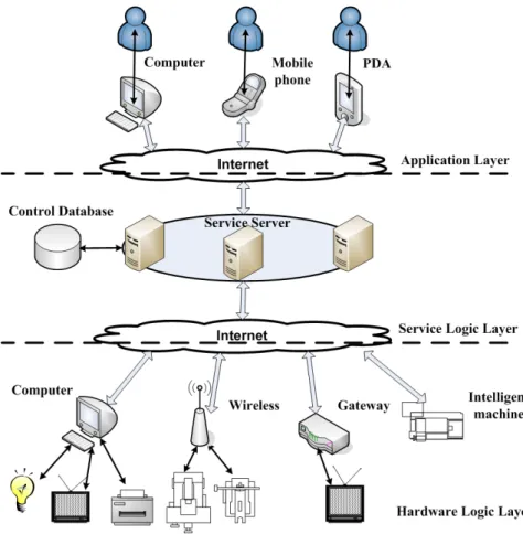
In order to overcome the limitations of the many-to-one architecture, the many-to-many architecture has been proposed. This method enables a platform to support multi-user and multi-machines. The idea is to break the close link between the server and the controlled machines. Based on SOA, controlled machine functions are provided as services. The machines communicate with a central control server via the internet in a loose-coupled way. The general framework of the many-to-many architecture is shown in figure 3.3. In this general framework the control structure is divided into three parts: Application layer, Service Logic Layer and Hardware Logic layer. The application layer offers a user interface for different users to access the service system. The service logic layer is the kernel part of the
system, not only because it connects users with machines, it is also designed for supporting all kinds of remote control services that can offer different controls according to users’ needs. The service logic can be deployed on different servers, and there may be control data support these services. The actual control application is located in the hardware logic layer, where different machines can be accessed via different methods. As shown in Figure 3.3, the machine can be connected through a computer, a wireless router connection, a gateway or other internet devices.
Figure 3. 3 Many-to-many Remote Control Architecture
The essential improvement of this design is separating remote control service logic with control application so that it supports multi-access from both the user side and the device side. According to SOA, the idea behind the approach is that a controlled machine is considered as an independent component or service that can be registered with the service server. The communication link between the controlled machine and the service server is established according to an agreed standard. Compared to the many-to-one method, the control logic no longer has to be located on the same closed network with actual control application. In this
way, different machines in different places can be accessed remotely by the control system from anywhere via the internet.
Another important change is that the focus of the architecture is no longer about establishing a communication middleware. Instead, the focus is on providing a better service development environment. Existing middleware technology such as web service is used to achieve the communication over the internet for the machines.
Currently, research related to this architecture is described in [Walsh and Hong, 2001; Wang, et al., 2003; University Of Florida, 2004; Ha, Sohn and Cho, 2005, 2007; Helal, et al., 2005; Ha, et al., 2007; de Souza, et al., 2008]. Increasingly researchers have put their focus on service-based systems. However, the results still have drawbacks so that they do not offer flexible control services. Three different many-to-many architecture designs will be analysed according their types of problems.
Design problem 1: Lack of standardised mechanism to communicate and understand device level applications.
SOA can be applied to two levels of a remote control system over the internet: the device level and the enterprise level. Device level SOA aims at integrating different machines in to a unified control application so that there is no need to develop different drivers to get data from the machines. Enterprise level SOA aims at integrating different machine applications in to high level services, so that machine data and functions can be used to achieve more complicated tasks. There are some explanations for the differences in these two levels in [de Souza, et al., 2008]. A lot of technology and research is focussed on device level SOA [University Of Florida, 2004; Ha, Sohn and Cho, 2005; Helal, et al., 2005; Ha, et al., 2007; Ha, Sohn and Cho, 2007]. However, there is not as much research into the SOA based mechanism to further link enterprise level applications with different device level applications. Also, there is a lack of research in the mechanisms to exchange the information on how the machines can be operated between the two levels.
Firstly, due to the lack of mainstream SOA middleware technologies, some designs try to separate controlled machine application from the enterprise level remote control services, however they fail to separate them clearly. The researchers need to create their own methods to build communication between servers and controlled machines over the internet. For
example, Wang, et al. [Wang, et al., 2003] proposes a web-based remote control service system that is supposed to support multiple services and is self-organising. From the architecture shown in Figure 3.4, the system is designed according to the many-to-many architecture as it allows different users to control different machines via a system built upon the internet.
Figure 3. 4 Overview Of The Web-based Remote Control Service System Adapted From [Wang, et al., 2003]
The main benefit of this design is to achieve a server that supports self-organised processes. Figure 3.5 shows a remote control factory would create the objects of service. A model called the component image factory will generate console image and device image, which can then communicate with the remote machine and console using XML-based messages. In this way, the machine side application can be separated from the main server and communicate with the server using messages. However, most of the work in the system has to be put into creating a “self-organisation” process, which is actually a method to achieve communication with distributed remote machines.
This kind of design lacks a communication standard over the internet, which will make the resulting system rely heavily on a particular platform, language or implementation environment. This kind of design also lacks consideration for offering control services,
![Figure 2. 2 Web Service Architecture Adapted From [Barry and Gannon, 2003]](https://thumb-us.123doks.com/thumbv2/123dok_us/10951365.2983655/29.892.215.741.546.968/figure-web-service-architecture-adapted-barry-gannon.webp)
![Figure 3. 4 Overview Of The Web-based Remote Control Service System Adapted From [Wang, et al., 2003]](https://thumb-us.123doks.com/thumbv2/123dok_us/10951365.2983655/40.892.218.738.306.682/figure-overview-based-remote-control-service-adapted-wang.webp)
![Figure 3. 5 Hierarchy Of Remote Control Server Adapted From [Wang, et al., 2003]](https://thumb-us.123doks.com/thumbv2/123dok_us/10951365.2983655/41.892.161.675.247.597/figure-hierarchy-remote-control-server-adapted-wang-et.webp)
![Figure 3. 6 Conceptual Architecture Of ubiHome Infrastructure Adapted From [Ha, Sohn and Cho, 2007]](https://thumb-us.123doks.com/thumbv2/123dok_us/10951365.2983655/42.892.203.750.583.988/figure-conceptual-architecture-ubihome-infrastructure-adapted-sohn-cho.webp)
![Figure 3. 7 Detail Architecture Of ubiHome Adapted From [Ha, Sohn and Cho, 2007]](https://thumb-us.123doks.com/thumbv2/123dok_us/10951365.2983655/43.892.214.748.534.882/figure-architecture-ubihome-adapted-ha-sohn-cho.webp)
![Figure 3. 8 Architecture Of The Smart Space Middleware Adapted From [Helal, et al., 2005]](https://thumb-us.123doks.com/thumbv2/123dok_us/10951365.2983655/45.892.193.763.335.723/figure-architecture-smart-space-middleware-adapted-helal-et.webp)