Systematic Testing of Embedded Automotive Software:
The Classification-Tree Method for Embedded Systems (CTM/ES)
Mirko Conrad
DaimlerChrysler AG, Research and Technology, Berlin, Germany
L
The software embedded in automotive control systems increasingly determines the functionality andproper-ties of present-day motor vehicles. The development and test process of the systems and the software em-bedded becomes the limiting factor. While these challenges, on the development side, are met by employing model-based specification, design, and implementation techniques [KCF+04], satisfactory solutions on the testing side are slow in arriving. With regard to the systematic selection (test design) and the description of test scenarios especially, there is a lot of room for improvement. Thus, a main goal is to effectively minimize these deficits by creating an efficient procedure for the selection and description of test scenarios for em-bedded automotive software and its integration in the model-based development process.
The realization of this idea involves the combination of a classical software testing procedure with a technol-ogy, prevalent in the automotive industry, which is used for the description of time-dependent stimuli signals. The result of this combination is the classification-tree method for embedded systems, CTM/ES [Con04]. The classification-tree method for embedded systems complements model-based development by
employ-ing a novel approach to the systematic selection and description of the test scenarios for the software em-bedded in the control systems. CTM/ES allows for the graphic representation of time-variable test scenarios on different levels of abstraction: A problem-oriented, compact representation, adequate for a human tester and containing a high potential for reusability, is gradually being transformed into a solution-oriented techni-cal representation which is suited for the test objects’ stimulation. The CTM/ES notation facilitates a consis-tent representation of test scenarios which may result from different test design techniques. The test design technique which this method is primarily based on, is a data-oriented partitioning of the input domain in equivalence classes. Secondary test design techniques are, for instance, the testing of specific values (or value courses) or requirement-based testing.
Within a model-based development process for embedded automotive software CTM/ES can be combined with structural testing on the model level in order to form an effective test strategy for model-based testing. Systems which have been developed in a model-based way can be tested systematically and efficiently by means of the CTM/ES and the tools based thereon, such as the classification-tree editor for embedded sys-tems CTE/ES [Mis04, CTE/ES], as well as the model-based test environment MTest [LBE+04, MTest].
INTRODUCTION
The rapid increase in the software complexity of today’s ECUs makes testing a central and significant task within embedded automotive software development. Dynamic Testing, meaning the execution of a test object with se-lected (sequences of) test data for the analysis of behavior in these cases, is the most important and most wide-spread measure for software quality assurance.
Since exhaustive testing is impossible in practice, dynamic testing is always a sampling procedure. A subset of test scenarios1 which is as small as possible and which is able to reveal as many errors in the test object as
pos-sible, needs to be selected from the complete set of possible test scenarios. The selection of adequate sample elements (test scenarios) decides on the extent and quality of the whole test.
1 General description of a test case which specifies a set of (detailed) test data or test data sequences.
The work described was partially supported by the IMMOS project funded by the German Federal Ministry of Education and Research (project ref. 01ISC31D)
Because of the exceptional significance of the selection process there is a need for systematic techniques which support the tester when designing adequate test scenarios. The application of these test design techniques2
systematizes the selection of test scenarios and makes it both comprehensible and reproducible [Sim97]. In addition to the test design techniques, there is a need for suitable notations for the documentation of the se-lected test scenarios. The automatic creation of test scenarios of functional tests is desirable but only possible to a limited extent. As a result, test design must largely be carried out manually. It requires a test (scenario) nota-tion which caters for the human tester.
When testing embedded automotive software, an ad-hoc selection of test scenarios is typical, i.e. the test sce-narios are determined without (explicitly) defined test design techniques. This selection depends on the experi-ence and expertise of the tester and can only be reproduced with difficulty, if at all. An ad-hoc selection of test scenarios leads, on the one hand, to test scenarios which are more or less redundant and, on the other hand, to test gaps. As a rule, it is impossible to make statements as to the quality or completeness of the ad-hoc test scenarios. With regard to the number of test scenarios, their level of error detection is often inadequate.
The test notations which are often used when developing automotive control software, such as the direct de-scription of the test scenarios in the form of time-dependent value courses or the use of test scripts, lead to a description of test scenarios on a very low level of abstraction, making maintainability and reuse difficult. In addi-tion, the methodical support for the use of the notations is insufficient.
In order to effectively minimize these deficits, the Classification-Tree Method for Embedded Systems (CTM/ES), an efficient procedure for the selection and description of test scenarios for embedded automotive software, was developed.
THE CLASSIFICATION-TREE METHOD FOR EMBEDDED SYSTEMS (CTM/ES)
The CTM/ES [CDF+99, Con04], an extension of the Classification-Tree Method [GG93], is a black-box test de-sign technique which allows systematic test dede-sign for embedded systems and their control software as well as a comprehensive graphical description of time-dependent test scenarios by means of abstract signal waveforms that are defined stepwise for each input. The basic concept is to split up the input domain of the test object ac-cording to different aspects usually corresponding to different input data sources. The different partitions, called classifications, are subdivided into (input data) equivalence classes. Finally, different combinations of input data classes are selected and arranged into test sequences.
The starting point for the proposed systematic test design approach is an interface description of the test object. Based on this, and by using the Classification-Tree Method for Embedded Systems, the tester can derive test scenarios systematically and describe them graphically.
Example PedInt
For illustration purposes a simplified component is used to interpret the pedal positions within a passenger car. This subsystem can be employed as a preprocessing component for various vehicle control systems. The pedal interpretation (short: PedInt) subsystem interprets the current, normalized positions of accelerator and brake pedal (phi_Acc, phi_Brake) by using the actual vehicle speed (v_act) as desired torques for drivetrain and brake (T_des_Drive, T_des_Brake). Furthermore, two flags (AccPedal, BrakePedal) are calculated which indicate whether or not the pedals are considered to be depressed.
The software requirements on the PedInt component are summarized in Tab 1. For the following considerations, those sub-functions of PedInt should be tested which both flags calculate (SR-PI-01.x). Fig. 1 shows the func-tional Simulink model for the PedInt component which was developed based on the requirements.
2 Standardized procedures for selecting test scenarios on the basis of certain sources of information (e.g. functional
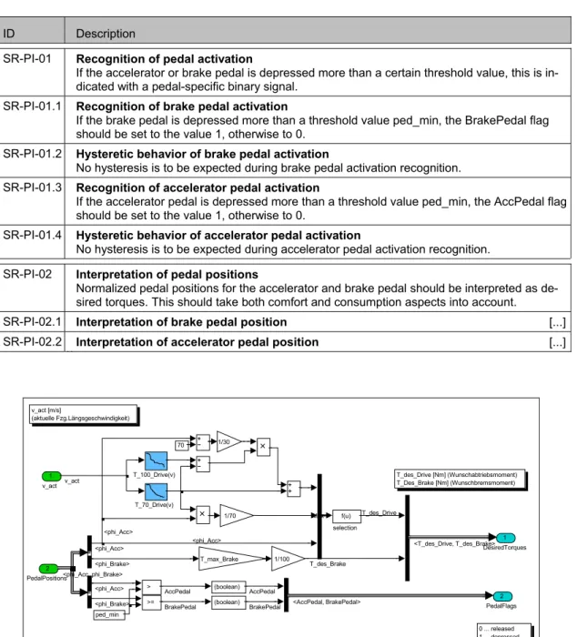
Table 1: Software requirements specification of PedInt (excerpt)
ID Description
SR-PI-01 Recognition of pedal activation
If the accelerator or brake pedal is depressed more than a certain threshold value, this is in-dicated with a pedal-specific binary signal.
SR-PI-01.1 Recognition of brake pedal activation
If the brake pedal is depressed more than a threshold value ped_min, the BrakePedal flag should be set to the value 1, otherwise to 0.
SR-PI-01.2 Hysteretic behavior of brake pedal activation
No hysteresis is to be expected during brake pedal activation recognition. SR-PI-01.3 Recognition of accelerator pedal activation
If the accelerator pedal is depressed more than a threshold value ped_min, the AccPedal flag should be set to the value 1, otherwise to 0.
SR-PI-01.4 Hysteretic behavior of accelerator pedal activation
No hysteresis is to be expected during accelerator pedal activation recognition. SR-PI-02 Interpretation of pedal positions
Normalized pedal positions for the accelerator and brake pedal should be interpreted as de-sired torques. This should take both comfort and consumption aspects into account. SR-PI-02.1 Interpretation of brake pedal position [...] SR-PI-02.2 Interpretation of accelerator pedal position [...]
0 ... released 1 ... depressed T_des_Drive [Nm] (Wunschabtriebsmoment) T_Des_Brake [Nm] (Wunschbremsmoment) v_act [m/s] (aktuelle Fzg.Längsgeschwindigkeit) PedalPositions [%] (normierte Pedalwege) 2 PedalFlags 1 DesiredTorques f(u) selection 70 ped_min T_70_Drive(v) T_100_Drive(v) >= > Mux 1/100 T_max_Brake 1/30 1/70 (boolean) (boolean) 2 PedalPositions 1 v_act <T_des_Drive, T_des_Brake> v_act <phi_Brake> <phi_Acc, phi_Brake> <phi_Acc> <phi_Acc> <phi_Acc> T_des_Drive <phi_Acc> <phi_Brake> AccPedal
BrakePedal <AccPedal, BrakePedal> AccPedal
BrakePedal
T_des_Brake
Figure 1: Simulink model of PedInt component
TEST INTERFACE DETERMINATION
In the first step, the interface which is relevant for the test has to be determined. Let the basis of further consid-erations be a test object with n inputs to be stimulated and m outputs to be observed. The input interface I of the test object is represented via the input variables ii (i=1,...,n), the output interface O via the output variables oj
In order to test the test object, each input variable of the effective test interface has to be stimulated with a time-variant signal. The output variables have to be recorded. Thus, the effective test interface determines the signa-ture of the test scenarios belonging to it:3
I: i1*: Time Æ I1 O: o1*: Time Æ O1
... …
in*: Time Æ In om*: Time Æ Om
Example PedInt
Table 2 describes the effective test interface I ∪ O of the PedInt component.
Table 2: Interface description of PedInt
variable ↔ unit domain data type v_act ► m/s [-10,70] real phi_Brake ► % [0,100] real phi_Acc ► % [0,100] real T_des_Drive ◄ Nm real T_des_Brake ◄ Nm real AccPedal ◄ — {0,1} bool BrakePedal ◄ — {0,1} bool Thus, the signature for the fundamental functional test scenarios is as follows:
I: phi_Acc*, phi_Brake*: Time Æ R|[0,100] O: T_des_Drive*, T_des_Brake*: Time Æ R
v_act*: Time Æ R|[-10,70] AccPedal*, BrakePedal*: Time Æ {0,1}
TEST INPUT PARTITIONING
In a second step, the admissible values of the signals which form the effective input interface must be disjoint-edly and completely partitioned into (equivalence) classes which are suitable abstractions of individual input val-ues for testing purposes. The partitioning is graphically represented by means of a classification-tree.
The partitioning aims to achieve a selection of the individual equivalence classes in such a way that they behave homogeneously with respect to the detection of potential errors. That is, the test object behaves either correctly or erroneously for all the values of one class (uniformity hypothesis).
A heuristic procedure has proved successful in approaching this ideal partitioning as much as possible in prac-tice. The inputs’ data types and value ranges provide the first valuable clues to partitioning: where real-valued data types with minimum and maximum values established are concerned, it is possible, for example, to create a standard class each for the boundary values, for the value of zero and for those intervals in between [Con04]. In general, the data type-specific, standard classifications are not detailed enough for a systematic test. They have to be refined or modified manually in order to approach partitioning according to the uniformity hypothesis. Example PedInt
According to standard partitioning for real-valued signals, the pedal positions which can take values from the range of 0% to 100%, would be partitioned into 3 classes 0, ]0, 100[, and 100
.
For the vehicle speed the five partitions-10, ]-10,0[, 0, ]0,70[, and 70 are obtained4.
3 I
i and Oi are the sets of admissible values for the variables ii and oi respectively.
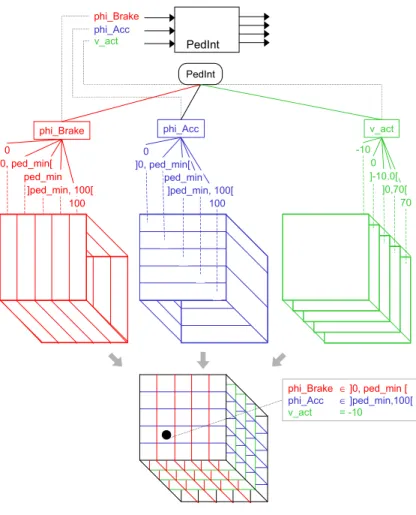
PedInt phi_Brake 0 100 v_act phi_Acc 0 100 -10 70 0 ]0,70[ ]-10,0[ ]ped_min, 100[ ped_min ]0, ped_min[ ]ped_min, 100[ ped_min ]0, ped_min[ phi_Brake phi_Acc v_act PedInt phi_Brake ∈ ]0, ped_min [ phi_Acc ∈ ]ped_min,100[ v_act = -10
Figure 2: From test interfaces to classification-trees
As v_act is only of secondary importance for testing those sub-functions of PedInt which both flags calculate, the standard classification has not been modified there. On the other hand, the evaluation of the pedal positions rec-ognizes a pedal as depressed only if it is activated above a certain threshold value ped_min. Therefore, the pedal values above and below the threshold should be considered separately because behavior is expected to differ. A class has also been added for the exact threshold value. In order to keep the classification-tree flexible, parameter names were partly used as class boundaries rather than fixed values. The result is a final partitioning of the pedal positions into the classes 0, ]0, ped_min[, ped_min, ]ped_min, 100[, and 100
.
The partitioning into classes is visualized by means of a classification-tree (Fig. 2, middle part). The lower part of Fig. 2 shows how the equivalence classes for the individual input variables partition the input domain of the
en-tire test object.
TEST SCENARIO DETERMINATION
In the third step, test scenarios are determined based on the test input partitioning. The test scenarios describe the course of these inputs over time in a comprehensive, abstract manner. Each scenario captures a data ab-straction of the test object's inputs and thus describes – largely independent of detailed test data – what is to be tested.
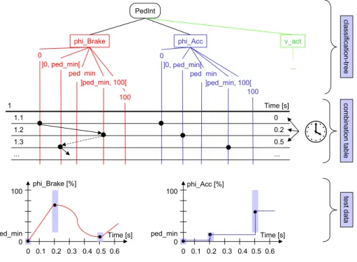
The classification-tree is used to define the columns of a combination table. In order to represent test scenarios in an abstract way, they are decomposed into individual test steps. These compose the rows of the combination table according to their temporal order (Fig. 3, middle part).
The input situation for each test step is defined by combining classes of different classifications from the classifi-cation-tree. This is done by marking the appropriate tree elements in the main column of the combination table. This leads to a sequence of input situations. The duration of each input situation can be captured by the annota-tion of time tags in the rightmost column of the combinaannota-tion table (Fig. 3, middle part).
: PedInt phi_Brake 0 ]0, ped_min[ ped_min 100 ]ped_min, 100[ v_act phi_Acc 0 ]0, ped_min[ ped_min 100 ]ped_min, 100[ ... Time [s]
1 1.1 0 1.2 0.2 1.3 0.5 ... ... classification-tree com bination table test data 0 0.1 0.2 0.3 0.4 0.5 0.6 100 ped_min 0 phi_Brake [%] Time [s] 0 0.1 0.2 0.3 0.4 0.5 0.6 100 ped_min 0 phi_Acc [%] Time [s]
Figure 3: Defining test sequences
Time-dependent behavior, i.e. changing the values of a input over time in successive test steps can be modeled by marking different classes of the classification corresponding to that input. The stimulus signal in the respec-tive test step is thus restricted to the part-interval or single value of the marked class. The combination of the marked input classes of a test step determines the input of the test object at the respective time (Fig. 3, middle part).
The intermediate values of the individual stimuli signals are defined by transitions between markings of consecu-tive test steps. Different transition types represent different signal shapes (e.g. ramp, step function, sine; cf. Tab 3). In this way stimuli signals can be described in an abstract manner with the help of parameterized, step-wise defined functions (Fig. 3, middle and lower part).
Table 3: Assignment of signal shapes for line types
signal shape transition type step
ramp ————— sine / spline - - -
Further test sequences can be described underneath the classification-tree by using the procedure mentioned above.
Example PedInt
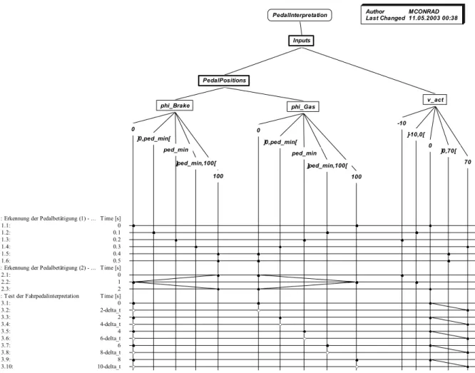
In a first test scenario (Fig 4, test scenario #1), the aim is to investigate the recognition of pedal activation with specific values, each of which are kept constant for a certain period of time.
A second test scenario (Fig 4, test scenario #2) checks the hysteresis properties of the test object. In order to do this, the pedal positions are varied, in the form of a ramp, over the entire value area, each going upwards and downwards once. In doing so, classes are selected arbitrarily for v_act.
In the case of different pedal positions, a third test scenario (Fig 4, test scenario #3), passes over the entire non-negative speed area linearly for each one. phi_Acc is varied over all the classes in 2s rhythm, whilst the other two classifications are each simulated with unchanging behavior (phi_Brake = 0, v_act increases linearly in a
standard way). 0 ]0,ped_min[ phi_Brake ped_min ]ped_min,100[ PedalPositions 100 0 ]0,ped_min[ PedalInterpretation phi_Gas ped_min Inputs ]ped_min,100[ 100 Author
Last Changed MCONRAD11.05.2003 00:38
-10 ]-10,0[ v_act 0 ]0,70[ 70 10-delta_t 3.10: 8 3.9: 8-delta_t 3.8: 6 3.7: 6-delta_t 3.6: 4 3.5: 4-delta_t 3.4: 2 3.3: 2-delta_t 3.2: 0 3.1: Time [s] 3: Test der Fahrpedalinterpretation
2 2.3: 1 2.2: 0 2.1: Time [s]
2: Erkennung der Pedalbetätigung (2) - ... 0.5 1.6: 0.4 1.5: 0.3 1.4: 0.2 1.3: 0.1 1.2: 0 1.1: Time [s] 1: Erkennung der Pedalbetätigung (1) - ...
Figure 4: Classification-tree with test scenarios for PedInt
TEST DATA REFINEMENT
In a fourth step, the abstract test scenarios will be refined into signal waveforms.
The test scenarios gained so far contain abstracted stimulus information because only equivalent classes, but no specific data have been used. Thus, in a further step, the test data is instantiated by the use of specific num-bers.
The test scenarios defined in the combination table form signal corridors for the individual input signals, within which the actual courses of input values must be located. The borders of the equivalent classes form the con-straints of the value ranges at the respective test steps. This step is illustrated in the lower part of Fig. 3.
Example PedInt
On the basis of the uniformity hypothesis any value within the marked interval can be selected when determining the values at the base points. Within the scope of this example the principle of mean value testing is being used, i.e. in each case the mean values of the equivalence classes selected are used as test data (ped_min = 5 %,
Fig. 5). 0 0.2 0.4 phi_Brake phi_Acc v_act -100 5 70 100 time [s] Test 1 / Test sequence 1
0 1 2 phi_Brake phi_Acc v_act 0 50 100 time [s] Test 1 / Test sequence 2
0 5 10 phi_Brake phi_Acc v_act 0 50 100 time [s] Test 1 / Test sequence 3
Figure 5: Test data curves PedInt
What has been presented so far, is how to systematically determine and compactly and adequately describe test scenarios for the black-box test of automotive control software with the help of CTM/ES.
THE UNDERLYING TEST MODEL
CTM/ES can be seen as a model-based testing approach [EW01], which is based on an abstract model of the input data space of the test object.
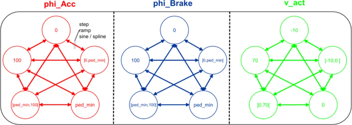
The data-oriented test input partitioning of the CTM/ES implicitly applies a parallel state-machine model to de-scribe the test input space. Each variable of the effective test input interface forms one of the parallel parts (AND-states) of the state machine. The states denote the individual equivalence classes defined for the variable. Test sequences can be viewed as pathes through such a test model.
Making these underlying test models explicit, allows to compare the CTM/ES with other model-based testing approaches. Furthermore, the test model can be used to formalize different test coverage criteria.
Example PedInt
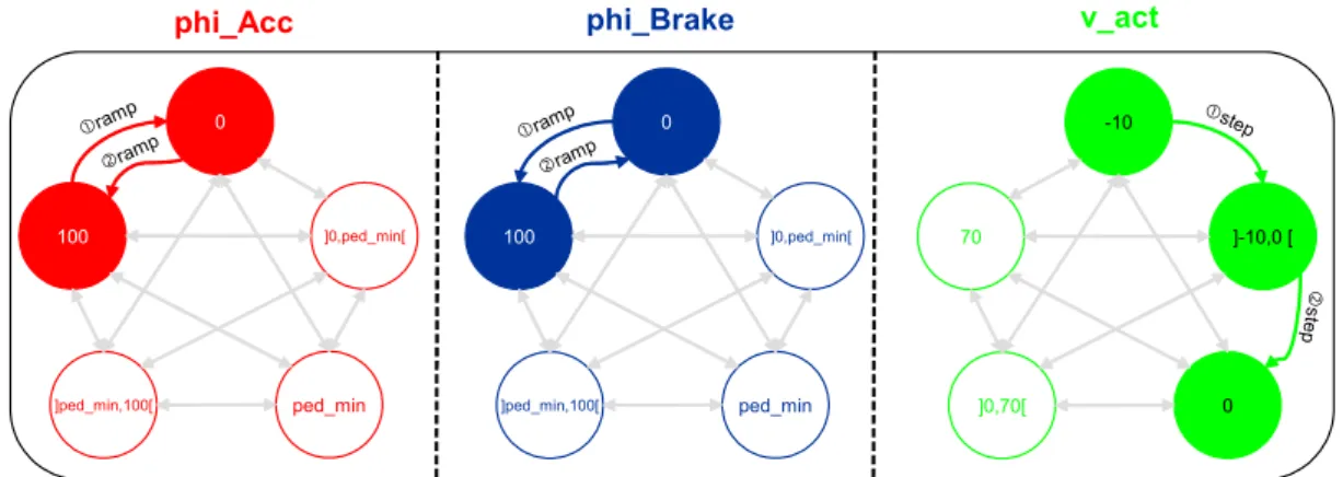
Fig. 6 shows the implicit test model for the PedInt example. Fig. 7 illustrates how test scenario #3 (cf. (Fig 4) can be understood as a path through the test model.
100 ]0,ped_min[ ped_min ]ped_min,100[ 0 100 ]0,ped_min[ ped_min ]ped_min,100[ 0 70 ]-10,0 [ 0 ]0,70[ -10
phi_Acc phi_Brake v_act
step ramp sine / spline
100 ]0,ped_min[
ped_min ]ped_min,100[
0
phi_Acc phi_Brake v_act
cramp 100 ]0,ped_min[ ped_min ]ped_min,100[ 0 dramp cramp dramp 70 ]-10,0 [ 0 ]0,70[ -10 cstep d ste p
Figure 7: Visualization of test scenario #3
A TEST STRATEGY FOR AUTOMOTIVE CONTROL SOFTWARE
CTM/ES can be deployed as a black-box test design technique, independently from an actual development process. The only pre-requisites are the description of the test object’s behaviour and interface.
A typical field of application is the deployment of CTE/ES within the framework of model-based development of automotive control software.
MODEL-BASED DEVELOPMENT
Model-based development can be regarded as an answer of numerous automobile OEMs and suppliers to the
increased demands on the development of embedded software [KCF+04]. This innovative development ap-proach is characterized by the integrated deployment of executable graphical models for specification, design and implementation, using commercial modeling and simulation environments such as MATLAB/Simulink/Stateflow [Matlab]. These tools use block diagrams and extended state machines as model-ing notations.
Very early in this development procedure an executable model of the control software (functional model) is cre-ated, which can be simulated as well as tested. This executable model is used throughout the downstream de-velopment process and forms the 'blueprint' for the automatic or manual coding of the embedded software and its integration into the electronic control unit (ECU). The seamless utilization of models facilitates highly consis-tent and efficient development.
MODEL-BASED TEST STRATEGY
Within the model-based development procedure it is essential to subject the software and its preliminary stages (models) to an appropriate combination of testing techniques in order to detect errors and produce confidence in its correct functioning. Such test strategies have to include combinations of functional and structural testing tech-niques. Furthermore, they must take into account the specifics of model-based development and especially the existence of an executable model in an adequate way.
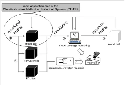
The systematic selection of test scenarios from the functional specification, the interfaces, as well as the execu-table model of the embedded software forms the focal point of such a model-based test strategy. In addition, an adequate structural test criterion is defined on model level, with the help of which the coverage of the tests thus determined can be evaluated and the definition of complementary tests can be controlled. If sufficient test cov-erage has thus been achieved on model level, the functional as well as the structural scenarios can be reused for testing the control software generated from the model and the control unit within the framework of back-to-back tests. In this way, the functional equivalence between executable model and derived forms of representa-tion can be verified (see [CFS04, Con04]). The model-based test strategy, which results from the above men-tioned steps, is schematically depicted in Fig. 11.
funct ional testi ng structura l testi ng moni toring % model test software test
model coverage monitoring
ECU test
model test
comparison of system reactions ?
≈
c d e
f
main application area of the
Classification-tree Method for Embedded Systems (CTM/ES)
TESTED
Figure 8: Model-based test strategy
TOOL-SUPPORT
The systematic definition of functional test scenarios with CTM/ES is supported by the classification-tree editor CTE/ES [Mis04, CTE/ES]. Comprehensive automation of functional testing on model level (step c) is possible with the model-based test environment MTest [LBE+04, MTest], which utilizes the CTE/ES for the test design. Monitoring of model coverage (step d) can be carried out by the Simulink model coverage tool [SL-VV] or the monitoring component of Reactis Tester [Reactis].
An automation of structural test design on model level (step e) is possible with Reactis Tester [Reactis, Ran03] or with an extended version of the evolutionary testing system ET [BCS+03, WSB01].
The execution of back-to-back tests between model and the control software derived from it (step f) can again be carried out with MTest. In order to also check the embedding of the software in the control unit, test scenarios can be exported from MTest to AutomationDesk [AUD, LRR03]. There, it can be reused for the (Hardware-in-the-Loop) test of the control unit.
The results of back-to-back tests can be analyzed with the help of MEval [CFP03, MEval].
SUMMARY AND CONCLUSION
The selection of suitable, i.e. error-sensitive, test scenarios (test design) is the most crucial activity for a trust-worthy software test. It ultimately determines the scope and quality of the test. Moreover, an appropriate descrip-tion of the test scenarios used is essential for the human tester, particularly when developing embedded auto-motive software.
A systematic approach for the selection of test scenarios and a notation for their appropriate description, must therefore form the core elements of a testing approach for automotive control software. In order to allow testing to begin at an early stage, test design should build upon development artifacts available early on, such as the specification or an executable model.
Current practice, however, is characterized by test scenario design according to a gut feel approach, leading to test gaps and test redundancies. In this paper a new, more systematic way of testing automotive control soft-ware has been presented. The core element of the approach is the Classification-tree Method for Embedded Systems (CTM/ES).
Based on the data-oriented partitioning of the input domain into equivalence classes, time-variable test scenar-ios can be derived systematically and described graphically. A compact, problem-oriented representation, suit-able for a human tester and containing a high potential for reusability, is transformed into a technical representa-tion which is suited to the test objects’ stimularepresenta-tion.
CTM/ES can be seen as a model-based testing approach, which is based on an abstract model of the input data space of the test object. Making this underlying test model (a parallel state-machine) explicit, eases the com-parison of CTM/ES with other model-based testing approaches and allows to formalize different test coverage criteria.
The CTM/ES enables the unified representation of test scenarios which result from other (functional and struc-tural) test design techniques. It can thus be employed as a universal means of description for almost all the test scenarios which arise as part of automotive control software testing. Another distinct advantage of the CTM/ES is that it can even be applied in situations in which the specification is incomplete or out of date.
The CTM/ES has recently been successfully employed in different software development projects. One of the main application areas is the testing of automotive software developed in a model-based way. To seamlessly support this application area, functional (black-box) testing with the CTM/ES was combined with structural (white-box) testing on model level. This combination, together with the subsequent reuse of the test scenarios for software and ECU testing, leads up to an integrated model-based test strategy.
Embedded automotive software which has been developed in a model-based way can be tested systematically and efficiently by means of the CTM/ES and the tools based thereon, such as the classification-tree editor CTE/ES, as well as the model-based test environment MTest.
REFERENCES
[AUD] AutomationDesk (product information). dSPACE GmbH, www.dspace.de/ww/en/pub/products
[BCS+03] Baresel, A., Conrad, M., Sadeghipour, S., Wegener, J.: The Interplay between Model Coverage and Code Coverage, 11. Europ. Int. Conf. on Software Testing, Analysis and Review (EuroSTAR 03), Amsterdam, NL, 2003.
[CDF+99] Conrad, M., Dörr, H., Fey, I., Yap, A..: Model-based Generation and Structured Representation of Test Scenarios. Workshop on Software-Embedded Systems Testing (WSEST’99), Gaithersburg, US, 1999
[CFP03] Conrad, M., Fey, I., Pohlheim, H.: Automatisierung der Testauswertung für Steuergerätesoftware. VDI-Berichte, Vol. 1789, VDI Verlag, 2003, pp. 299-315.
[CFS04] Conrad, M., Fey, I., Sadeghipour S.: Systematic Model-Based Testing of Embedded Automotive Soft-ware - The MB3T Approach. ICSE 2004 Workshop W14S on Software Engineering for Automotive Systems (SEAS '04), Edinburgh, UK, May 2004
[Con04] Conrad, M.: Modell-basierter Test eingebetteter Software im Automobil - Auswahl und Beschreibung von Testszenarien. PhD Thesis, Deutscher Universitätsverlag, Wiesbaden, Germany 2004
[CTE/ES] CTE for Embedded Systems (product information). Razorcat Development GmbH, www.razorcat.com
[EW01] El-Far, I.K., Whittaker, J.A.: Model-based Software Testing. In J.J. Marciniak (Ed.): Encyclopedia of Software Engineering, 2nd edition, Wiley 2001.
[GG93] Grochtmann, M.; Grimm, K.: Classification Trees for Partition Testing. Software Testing, Verification and Reliability, 3, 63-82, 1993.
[KCF+04] Klein, T., Conrad, M., Fey, I., Grochtmann, M.: Modellbasierte Entwicklung eingebetteter Fahrzeug-software bei DaimlerChrysler. Lecture Notes in Informatics (LNI), Vol. P-45, Köllen Verlag, 2004, pp. 31-41
[LBE+04] Lamberg, K., Beine, M., Eschmann, M., Otterbach, R., Conrad, M., Fey, I.: Model-based testing of embedded automotive software using MTest. SAE technical paper #2004-01-1593, SAE World Con-gress 2004, Detroit, US, Mar. 2004.
[LRR03] Lamberg, K., Richert, J.; Rasche, R.: A New Environment for Integrated Development and Manage-ment of ECU Tests. SAE World Congress 2003, Detroit, US, Mar. 2003.
[Mis04] Mischke, J.: Classification-tree Editor for Embedded Systems CTE/ES Version 2.3 User Manual. BoD GmbH, 2004
[MEval] MEval (product information). IT Power Consultants, www.itpower.de/meval.html [MTest] MTest (product information). dSPACE GmbH, www.dspace.de/ww/en/pub/products [Reactis] Reactis Tester (product information). Reactive Systems Inc., www.reactive-systems.com
[Ran03] Ranville, S.: MCDC Unit Test Vectors From Matlab Models – Automatically. Embedded Systems Conference, San Francisco, US, 2003.
[Sim97] Simmes, D.: Entwicklungsbegleitender Systemtest für elektronische Fahrzeugsteuergeräte. PhD Thesis, Herbert Utz Verlag Wissenschaft, 1997.
[SL-VV] Simulink Verification and Validation Toolbox (product information). The MathWorks Inc., www.mathworks.com/products/simverification
[WSB01] Wegener, J., Sthamer, H., Baresel, A.: Evolutionary Test Environment for Automatic Structural Test-ing. Special Issue of Information and Software Technology, Vol. 43, pp. 851–854, 2001.
CONTACT
Mirko Conrad studied Computer Science at the Technical Universities Dresden and Berlin. Since 1995 he has been a project manager and research scientist at the Software Technology Lab of DaimlerChrysler Research and Technology. In 2004 he received his PhD from the TU Berlin for his work on model-based testing of embed-ded automotive software.
His main competencies are within the areas of model-based development and quality assurance of embedded automotive software. He co-developed the model-based testing tools CTE/ES, MTest and MEval. He is member of the Special Interest Group for Testing, Analysis and Verification of Software in the German Computer Society (GI TAV) and the MathWorks Automotive Advisory Board (MAAB).