Item #
Quantity
Required Description 1 1 Power Lock Assembly 2 1 Body Wire Harness 3 1 Tailgate Wire Harness
4 1 Hardware Bag
Kit Contents
Item # Quantity Description
1 2 3M T-taps Blue 18 to 16 AWG Tap 2 25 10” Cable Ties
3 1 Pre-assembled fuse harness (w/ B & G connector attached)
4 1 Bolt
5 2 Wire harness grommets
Hardware Bag
Installation Tools
Screw Gun/Drill Assembly Installation
10 mm socket Negative Battery Terminal Handle Mounting Bolt T30 "TORX" socket Tailgate Service Hole Cover 10 mm wrench Handle Mounting Bolt
Nylon Removal Tool
Kick Panels, Wire Harness Protector
Pliers T-Tap installation
Torque Wrench Battery Terminal 48 in-lbs Handle Mounting Bolt 49 in-lbs
Masking Tape
Recommended Tools
STOP: Damage to the vehicle may occur. Do not proceed until process has been complied with.
OPERATOR SAFETY: Use caution to avoid risk of injury.
CRITICAL PROCESS: Proceed with caution to ensure a quality installation. These points will be audited on a completed vehicle installation.
TOOLS & EQUIPMENT: This calls out the specific tools and equipment required for this process.
SAFETY TORQUE: This mark indicates that torque is related to safety.
Legend
INSTALLATION INSTRUCTIONSModel
PL8547HD
2007
-
2021 Toyota Tundra
Have a technical question?
Contact our Technical Support team for installation questions or concerns.
Technical Support: (920) 283 - 1933 Monday –Friday 8:30am to 4:30pm CST
Replacement or Warranty Claim?
Contact Customer Service for general questions or to start a warranty claim.
Customer Service: 1 (844) 996 - 5625 Option 2 Monday –Friday 8:30am to 4:30pm CST
Suggested Accessory:
Installation
INSTALLATION PREPARATION:
Before starting installation
1. Familiarize yourself with the installation instructions.
2. Inspect kit components (Refer to kit contents and hardware bag contents).
1. VEHICLE PREPARATION
A. ”IMPORTANT…………..IMPORTANT”
Disconnect and isolate negative battery cable (Fig. 1-1)
a) Do not come in contact with the positive terminal during the removal of the negative cable.
B. Remove tailgate service hole cover.
(Fig 1-2) using a T30 "TORX" socket, remove the 8 screws and service hole cover. Add masking tape to all openings in tailgate around handle to cover sharp edges as shown in (Fig. 1-2)
Fig. 1
-
1
Fig. 1
-
2
10mm socket or wrench
C. Remove and discard passenger side
mounting bolt with an 10 mm socket (Fig. 1-4) .
2. Power Lock Actuator Assembly
A. Insert power lock assembly through second hole of sheet metal taking caution not to damage lock rod clip. (Fig. 1-5) Place the power lock assembly on to the handle. One hole in the bracket will align with the mounting bolt removed in the previous step. The other hole will surround a plastic post on the handle (Fig. 1-6A).
B. Place the provided mounting bolt in the mounting hole of the power lock bracket. (Fig. 1-6B) and verify that the post on the lock pawl protrudes through the slot on the power lock lever arm.
C. Tighten mounting bolt with 10mm torque
wrench (49 in-lbs).
Verify latch rods and clips are still engaged.
Fig. 1
-
4
Fig. 1
-
6B
10 mm socket or wrenchMounting Bolt Hole
Handle Post Hole
Fig. 1
-
6A
10mm socket or wrench
D. Remove back up wire harness grommet from the cross member of truck bed by pushing in the tabs on the grommet as well as bottom of tailgate using a nylon pry tool. Fig. 1-7. Throw away grommets once removed
E. Route the tailgate wiring harness through the back-up camera access hole on both the tailgate as well as the truck bed cross member using a wire puller (Fig. 1-8). The Female connector end should be in tailgate. Pull it through one of the central cut-outs of the longitudinal stiffening panels of the tailgate. Route the power
lock wire harness below the OEM camera harness. NOTE: It is best to pull all the
wire from the short harness up through the tailgate leaving only about 2 inches of wire and the Delphi plug exposed behind the truck bed cross member. This will make it easy to unplug for tailgate removal.
F. Using provided wire harness grommets
around both camera harness and short wire harness aligning the ends of the black shrink tube with both wire harness grommets (one at each end of the black shrink tube). Snap wire harness grommets into access holes on both tailgate and
truck bed cross member. NOTE: When
inserting tailgate grommet ensure the locking tab is in the same position as the removed OE grommet. Secure wire har-ness to camera cable using (2) cable ties making sure to keep power lock wire har-ness on the OEM camera harhar-ness (Fig. 1-9). Rotate head of zip tie so it faces
Fig. 1
-
7
Fig. 1
-
8
Truck bed crossBottom of tailgate
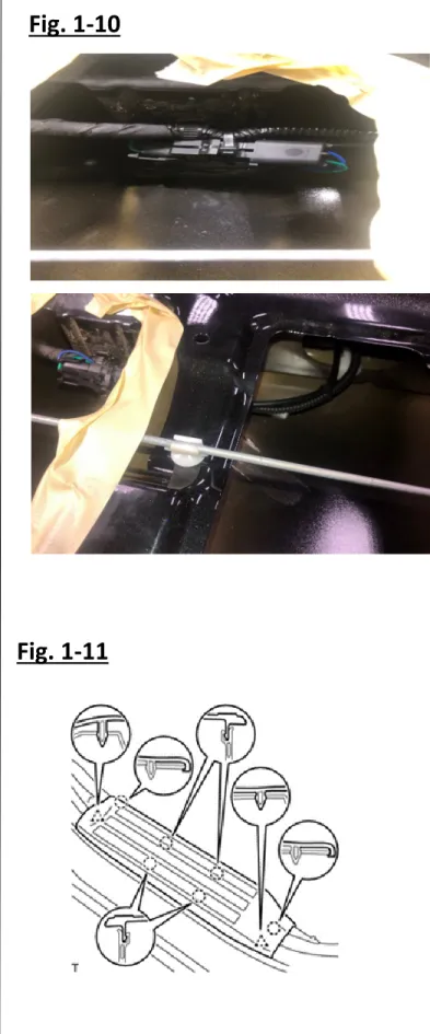
G. Connect the Female Connector end of the short wire harness to the Male Connector End of actuator on the power lock. Roll up and bundle extra wire with a (1) cable tie. With (1) cable tie secure bundle to OEM-tailgate wiring harness. Rotate head of zip tie so it faces down. (Fig. 1-10)
H. Remove the passenger side scuff plate. Note: Picture shown is for LH removal. Procedure is same for RH. (Fig. 1-11)
Fig. 1
-
11
I. Remove the passenger side kick panel by removing the nut that holds the kick panel in place. Gently pull the panel towards you carefully not to break any of the plastic. (Fig. 1-12)
J. From inside vehicle push carpet back and locate the rubber grommet in the floor pan. Using gasket punch to add a small hole in the grommet push end of body wire harness through grommet (Fig. 1-13).
NOTE: When pulling harness through the grommet leave 14 inches of the harness in-side the vehicle.
K. Pull long wire harness through grommet
and route towards back of vehicle. Re-install grommet. (Fig. 1-14)
Fig. 1
-
12
Fig. 1
-
14
Fig. 1
-
13
Note: Picture shown is for LH removal. Procedure is same for RH.
L. Route long wiring harness along factory harness below scuff plate and secure with cable ties. (Fig. 1-15) **Note** When securing harness do not secure to airbag harness (harness identified by yellow connector)
M. Locate the MJ1 connector (Fig. 1-16a). Locate the RED wire at pin 18 and connect the BLUE wire of the in-line fuse harness using the provided T-Tap. Locate the WHITE w/ SILVER DASH wire at pin 9 and connect the GREEN/WHITE STRIPE wire of the in-line fuse harness to the WHITE w/ SILVER wire using the provided T-Tap. (Fig. 1.16b) Bundle in-line fuse harnesses and secure with 2 cable ties to OEM wire harness (Fig. 1-16a)
Fig. 1
-
15
Fig. 1
-
16b
Actuator Vehicle Pin Tap Connector
Green/
White White w/ Silver Dash 9 Blue MJ1
Blue Red 18 Blue MJ1
Fig. 1
-
16a
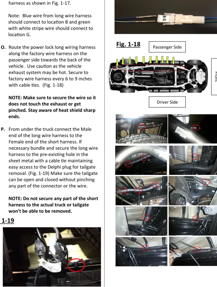
Connect green/white stripewire Connect blue wire hereN. Locate male connector housing on fuse harness and insert pins from long wire harness as shown in Fig. 1-17.
Note: Blue wire from long wire harness should connect to location B and green with white stripe wire should connect to location G.
O. Route the power lock long wiring harness along the factory wire harness on the passenger side towards the back of the vehicle. Use caution as the vehicle exhaust system may be hot. Secure to factory wire harness every 6 to 9 inches with cable ties. (Fig. 1-18)
NOTE: Make sure to secure the wire so it does not touch the exhaust or get
pinched. Stay aware of heat shield sharp ends.
P. From under the truck connect the Male
end of the long wire harness to the Female end of the short harness. If necessary bundle and secure the long wire harness to the pre-existing hole in the sheet metal with a cable tie maintaining easy access to the Delphi plug for tailgate removal. (Fig. 1-19) Make sure the tailgate can be open and closed without pinching any part of the connector or the wire.
NOTE: Do not secure any part of the short harness to the actual truck or tailgate won’t be able to be removed.
Fig. 1
-
17
Fig. 1
-
18
Passenger SideDriver Side Fr o n t
Fig. 1
-
19
Q.
Vehicle Re
-
Assembly
a. Put carpet back in placeb. Reinstall passenger side kick panel
c. Reinstall passenger side scuff plate
d. Reinstall tailgate service hole cover per Fig. 1-2.
e. Reconnect the vehicle’s negative battery cable.
i. Position the negative battery cable at the original factory position.
ii. Tighten the nut with 48 in-lbs of torque.
f. Do not come in contact with the positive terminal during the replacement of the negative cable.
Accessory Function Test
Note: Close tailgate before beginning function test.
Step
Perform
Look For
1 Press the key FOB lock button. The handle is locked and does not allow tailgate to open.
2 Press the key FOB unlock button twice. The handle is unlocked and allows the tailgate to open.
3 Press the vehicle lock button on door. The handle is locked and does not allow tailgate to open.
4 Press the vehicle unlock button on door. The handle is unlocked and allows the tailgate to open.
5 Lock the tailgate with the key. The handle is locked and does not allow tailgate to open.
6 Unlock the tailgate with the key. The handle is unlocked and allows the tailgate to open.
7 Rotate the key in driver door lock to the unlock position twice within seconds.
The handle is unlocked and allows the door tailgate to open.
8 Rotate the key in driver door lock to the lock position The handle is locked and doesnallows the door tailgate to open.’t
9
With the vehicle in reverse and viewing the backup monitor, manually actuate power door locks to check for interference on back up monitor.