Proceedings of 8th International Conference on Short and Medium Span Bridges
Niagara Falls, Canada 2010
THE EAGLE RIVER BRIDGE SUPERSTRUCTURE REPLACEMENT
Biljana Rajlic
Hatch Mott MacDonald, Canada Philip Murray
Hatch Mott MacDonald, Canada Dick Dykstra
Ministry of Transportation of Ontario – Northwest Region, Canada Raymond Krisciunas
Ministry of Transportation of Ontario – Northwest Region, Canada
ABSTRACT
This paper describes the unique rehabilitation method and structural details used for the Eagle River Bridge superstructure replacement. The existing superstructure of the Eagle River Bridge on the TransCanada Highway was a three-span continuous concrete slab on haunched steel girders. As a result of fatigue issues and deck deterioration, the Ontario Ministry of Transportation (MTO) decided to replace the entire superstructure. To address concrete quality issues, accelerate construction and reduce impact on the travelling public, the superstructure replacement was side-by-side prestressed concrete box girders. What was unique about this decision was to forgo the use of a distribution slab or transverse prestressing, while still creating a semi-continuous structure. Other bridge components including curbs, approach slabs, expansion joints and sleeper slabs were also prefabricated. Fibre reinforced polymer (FRP) bars were used to increase structural durability. They were also used throughout the prefabricated components, resulting in a virtually steel free superstructure.
The concept side-by-side prestressed concrete box girders without distribution slab or prestressing was common in the 1950s and „60s but was abandoned in Canada because of failure of transverse shear mechanisms due to environmental exposure. The use of contemporary ultra-high performance concrete (UHPC) has enabled the revival of this very effective construction technique. In past two years, MTO NW Region has designed and constructed several single-span bridges using this type of system. The Eagle River Bridge went a step further in that it was the first multi-span bridge designed with the side–by-side prestressed concrete box girders without a distribution slab. UHPC concrete achieved a singular negative moment connection detail in addition to concrete diaphragms thus making the girders continuous for all superimposed loads.
The Eagle River Bridge was designed as a semi-integral abutment bridge with expansion joints and sleeper slab at the end of approach slab. The new semi-integral abutment detail was developed to accommodate easy installation of the bridge prefabricated accessories.
1. BACKGROUND AND HISTORY
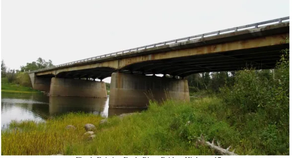
The Eagle River Bridge is located 30 km west of Dryden on Highway 17, which forms part of the Trans Canada Highway. The bridge was built in 1958 and had exhibited very serious fatigue concerns for a number of years requiring regular girder repairs. As well, the deck was suffering considerable deterioration due to salt exposure. The substructure, however, was in reasonably good condition. As a result of these conditions, it was decided in 2008 to replace the entire superstructure but retain the foundation elements.
The bridge was comprised of a three-span (26m, 34m, 26m) continuous variable depth steel girders, with a post-tensioned concrete deck (Fig. 1). Over the past 50 years, the structure was rehabilitated several times including expansion joint replacement and barrier wall replacement in early 1990s.
Fig. 1. Existing Eagle River Bridge, Highway 17
In determining a rehabilitation plan, however, the availability of HPC for cast-in-place (CIP) concrete in this area of the Province had to be considered. HPC delivery is a challenge as many of the NW Region‟s structures are isolated from major communities and suppliers. As well, mobilization costs for a portable concrete batching plant capable of producing high-quality HPC is excessive such that the use of proprietary “pre-packaged” concrete proved to be a more cost-effective solution.
To minimize the use of CIP concrete, bridge replacement projects in this region are undertaken using prefabricated components comprised of concrete girders, deck slabs, steel and timber beams. From a quality perspective, the prefabricated components are manufactured in a controlled environment. This facilitates consistent batching, time of placement, curing, temperature, release of forms and handling; all of which help to provide a product with consistent strength, durability and geometry, and dimensional stability. Not only does this solve the concrete supply issue, but it accelerates the construction of the structure, an important feature as the construction season is only from May till September. This approach has been used successfully since 2004 on many structures.
Historically, side-by-side box girders were used throughout Ontario as an efficient system for new bridges with a lightly reinforced or unreinforced distribution slab. The weak link in theses structures was the quality of the material in the shear key and their ability to share loads between the girders. Several methods were implemented including full distribution slabs and transverse post-tensioning which addressed these issues but increased the cost of this bridge, making them a more expensive solution. With the introduction of UHPC, a new high-quality, highly durable product, the need for a distribution slab was eliminated.
In the past two years, many of the bridge / deck replacements in NW Region have used side-by-side precast, prestressed concrete box girders without a distribution slab. Improved quality and durability through the prefabricated components using high-strength concrete have been obtained while maintaining a cost-effective low maintenance solution. To date, their use has been limited to simply supported spans.
To expand further on the range and efficiency of the box girders, a detail was developed to resist the negative moment connection over top of the piers by providing continuity for all superimposed loads. Connection details typically found in the industry would not work in this application as the need to minimize in-situ concrete was paramount as the unit cost for UHPC is considerably higher than normal concrete.
Several systems were reviewed. However, the chosen system needed to mimic the other details on the structure and use materials which would be readily available on site to maintain the cost effectiveness of this solution. The chosen connection system was a joint which used UHPC, the same material used to connect the box girders longitudinally (Fig. 2). In addition to improved quality achieved by using UHPC, bond development lengths were reduced substantially. To minimize any corrosion potential, a non-corrosive glass fibre reinforced polymer reinforcing (GFRP) was used throughout. Very small designed joints make the surrounding elements continuous and are easy and fast to produce.
Fig. 2. Side- by-side box girders plan view
2. DESIGN
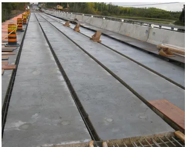
The Eagle River Bridge was an existing three-span structure with haunched steel girders and concrete deck slab approximately 1400mm deep superstructure. The substructure was rehabilitated to accommodate the new superstructure side-by-side box girders 1100 mm deep and 1240 mm of wide (Fig. 3 and Fig. 4) connected longitudinally and transversally with UHPC joints (Hatch Mott MacDonald 2009.).
Fig. 3. Typical section
Design was based on the Canadian Bridge Design Code CAN/CSA-S6-06 (CSA 2006), superior material characteristics of UHPC (LaFarge North America 2009) and results from previous pullout capacity testing of steel strands in UHPC (Lubbers and Steinberg 2003) and load testing of similar joints (Harryson 2003). UHPC is defined as a Portland Cement fibre composite having minimum characteristic design values of 140 MPa (20,000 psi)
compressive strength and 3 MPa (430 psi) direct tensile strength, in order to achieve a ductile behaviour (non-brittle failure) under compression and tension and, thereby, dispense passive (non-prestressed) reinforcement.
Fig. 4. Side-by-side box girders layout
The UHPC technology used for the joints was an ultra-high-strength, ductile material formulation made with constituent ingredients including Portland cement, silica fume, quartz flour, fine silica sand, high-range water reducer, water and steel fibres. Compressive strengths for bridge applications can range from 120 to 200 MPa (17,400 to 29,000 psi) and flexural strengths range from 15 to 40 MPa (2200 psi to 5800 psi).
The material‟s high mechanical properties are a result of proportioning the constituent ingredients to produce a modified compact grading with a nominal maximum coarse aggregate size of 400 µm, and a fibre geometry of 12 x 0.2 mm (½ x 0.008"). The ratio of maximum coarse aggregate size to fibre is important to facilitate random orientation of fibres and a ductile behaviour. These performance characteristics result in improved micro-structural properties of the mineral matrix, especially toughness and control of the bond between the matrix and fibre.
With a carbonation depth penetration of 0.5 mm (0.02″), there is almost no carbonation or penetration of chlorides or sulphides and a high resistance to acid attack. The superior durability characteristics are due to low porosity from a combination of fine powders, selected for their relative grain size (maximum 0.5 mm [0.02″]) and chemical reactivity. The net effect is a maximum compactness and a small, disconnected pore structure.
The material‟s ultra-high strength properties and low permeability also provide excellent protection of the rebar against corrosion and improved bond with the rebar, thereby providing short bond development lengths.
Table 1 indicates the range of material characteristics for UHPC Joint Fill.
Table 1 (a) Strength of UHPC joint fill Table 1(b): Durability of UHPC joint fill
Property Value Characteristic Value
Compressive (28 days) 140 MPa (20000 psi) Freeze/thaw (after 300 cycles) 100% Compressive (48 hours) 100 MPa (14500 psi) Salt-scaling (loss of residue) <0.10 g/m2 Flexural 30 MPa (4300 psi) Carbonation depth <0.5 mm Young‟s Modulus 50 GPa (7200 ksi)
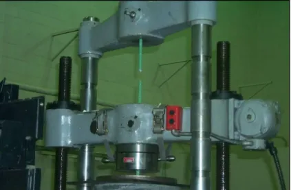
Various tests conducted to demonstrate the pullout capacity of steel strands in UHPC have shown that significantly shorter bond development lengths are required to fully develop the bars. Also, in 2004, testing was conducted to determine bond development lengths for GFRP in UHPC. The test program was undertaken at the labs of EBA Engineering Consultants Ltd. (Calgary) to develop a design recommendation.
Single GFRP bars were embedded into UHPC blocks at lengths of 100 mm (4″) and 150 mm (6″) (Fig. 5). The bars were loaded to failure in accordance with Annex B of CAN/CSA-S806-02 (CSA 2002). Test results (Table 2) show
that the mode of failure for the 150 mm (6″) embedment was a tensile force induced fracture of the GFRP rod, with no discernible slippage or detectable UHPC fracturing. For the 100 mm (4″) embedment, the failure was a delamination of the epoxy sand layer to the bar. Both embedment lengths failed in the bond of the epoxy sand coating. The force applied was compatible with the ultimate tensile strength capacity of an equivalent steel bar.
Table 2: Pullout test data – 15 mm GFRP in UHPC
Sample # Embedment Length Failure Load (N) Failure Mode 1 100 mm (4″) 67,110 GFRP Rod Rupture 2 150 mm (6″) 95,684 GFRP Rod Rupture
This test result validated the design which allowed for a precast bridge deck with a 210 mm (8″) wide joint compared to a conventional design of a 600 mm (24″) wide joint. This also permitted the use of the CHBDC simplified method of analysis (CSA 2006).
Fig. 5. Test set-up for pullout capacity of GFRP in UHPC block
Additional testing recently completed by the New York Department of Transportation (NYDOT) (Perry and Royce 2010.) investigated pullout test specimens manufactured with 13 mm, 16 mm and 19 mm (1/2″, 5/8″ and 3/4″) bar sizes in epoxy coated and black steel bars. Embedment lengths were 75 mm (3″) for the 13 mm (1/2″) Ø bar; 100 mm (4″) for the 16 mm (5/8″) Ø bar; and 125 mm (5″) for the 19 mm (3/4″) Ø bar. Failure behaviour of the pullout tests conducted on all samples was rebar failure (Fig. 6).
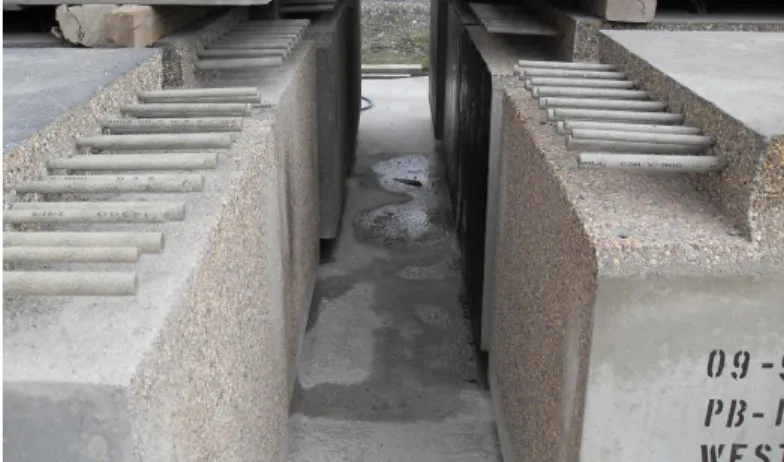
These tests concluded that precast elements connected by UHPC joints (Fig. 7) can be treated as monolithic members in design. Development length for 16 mm GFRP bar is 430 mm (Fig. 8). As per CSA 2006, a splice length for GFRP bars in tension is 1.3 time development length and spliced bars should not be separated by more than 150 mm. Based on this, the designed UHPC joint width was 650 mm. Similar to previously tested joints, transverse reinforcing bars were simply put on top of the spliced bars.
The surface of each precast girder had an exposed aggregate surface in the joint fill contact area to enhance bond between the precast girder and the joint fill (Fig. 9).
Fig. 6. Pullout test set-up (epoxy coated rebar) showing failure behaviour
Fig. 7. UHPC joint fill details (joint fill area)
Fig. 9. Box girders end showing GFRP reinforcing and exposed aggregate roughening
3. CONSTRUCTION
Construction of the Eagle River Bridge was scheduled to begin in summer, 2009. Engineering schedules anticipated construction completion in approximately four months. Work included removal of the existing bridge deck, local removals of the piers and abutments, in addition to localized patching of deteriorated concrete in the substructure. During the design phase, it was noted that the critical path was casting of the precast prestressed concrete box girders. Accordingly, it was decided to let a separate contract for the girders in advance of the main construction contract.
Several key issues surface during bridge rehabilitation when extensive use of precast is employed, including: 1. Variations in as-constructed dimensions of existing structure
2. Normal variations/tolerances in precast components 3. Quality of in-situ concrete for low quantities 4. Bonding of grout/infill concrete.
Impact from variations in the existing structure dimensions were minimized as the new construction included reconstruction of the abutment caps and pier caps (Fig. 10). This challenge was further complicated by the fact that drawings depicting the existing structure were not available and the exact dimensions of the substructure were unknown. Cast-in-place concrete at the abutments and piers was detailed to allow for variations up to 100mm.
This detailing approach was also the tool used to deal with normal tolerances in precast construction. For girders the approach was taken to align each girder at the abutments and install the centre span with equal distance on each size. Since the approach spans were installed first, detailed measurements of the as-constructed lengths of the main span girders were taken and used to ensure that a minimum of 85 mm was maintained between the girders longitudinally over each pier. To expedite installation of the girders, all reinforcing bars were kept short of the end of the girder. Once installed, continuity bars were placed in the closure strip and UHPC placed to complete the continuity link. As previously mentioned in-situ concrete in the Region is critical. Once the substructure was reconstructed to the elevations shown in contract drawings, the precast prestressed box girders were erected into place. Forms were installed at the piers and the gap between the girders was filled with UHPC in three stages to minimize pressure on the forms resulting from 1.2 m of full head (Fig. 7). The final stage included the negative moment closure strip which contains the longitudinal bars required to resist the negative moments. The joint area was congested with GFRP bars (Fig. 11), however, the fluid self-levelling nature of the UHPC assists with the consolidation of the concrete (Fig. 12).
Fig. 11. Plan view of reinforcing bars at transverse joint
4. CONCLUSION
The Eagle River Bridge superstructure replacement project pioneered the use of a UHPC joint for developing continuity over piers for multi-span precast concrete deck bridges. Testing to date indicates that rebar in UHPC has a much shorter bond development length and this provides opportunities for fully developed rebar in shorter joint widths.
5. ACKNOWLEDGEMENTS
The authors of the paper would like to thank various contributors for the information and photos supplied for the various aspects of the paper including Gary Weiss from MTO NW Region, Vic Perry from Lafarge North America, Rob Frenette and John Nurola from TBT Engineering and the bridge staff at HMM who met the tight project schedule making the project success possible.
6. REFERENCES
Canadian Standards Association. 2006. CAN/CSA – S6-06 Canadian Highway Bridge Design Code. Canadian Standards Association, Toronto, Canada.
Canadian Standards Association. 2002. CAN/CSA – S806-02 Design and construction of building components with fibre reinforced polymers. Canadian Standards Association, Toronto, Canada.
Hatch Mott MacDonald. 2009. Eagle River Bridge Rehabilitation Drawings. Ministry of Transportation, Northwest Region, Structural Section, Thunder Bay, Canada.
Harryson, P. 2003. High Performance Joints for Concrete Bridge Applications. Structural Engineering International, 13 (1): 69-75.
Lafarge North America. 2009. Product Data Sheet: Ductal® JS1000, www.imagineductal.com.
Lubbers, A. and Steinberg, E. 2003. Bond of Pre-stressing Strands in UHPC. International Symposium on High Performance Concrete, USA.
Perry, V., Royce, M. 2010. Innovative Field Cast UHPC Joints for Precast Bridge Decks (side-by-side deck-tees) Village of Lyons, NY. 3rd fib International Congress, USA.