© 2012–2013 Advanced American Telephones. All Rights Reserved. AT&T and the AT&T logo are trademarks of AT&T Intellectual Property licensed to Advanced American Telephones, San Antonio, TX 78219. Syn248® is a registered trademark of Advanced American Telephones. Issue 5.0 09/13
Syn248
Installation and
1
C
ONTENTS
Preface ... 4
Additional Documentation ...4 Topic Navigation ...5 Text Conventions...5Installation ... 6
System Overview ...7Software Version Compatibility...8
System Installation Overview...9
Recommended Installation Sequence... 10
Site Preparation... 11
Network Requirements... 11
Placement Considerations... 12
Power Considerations ... 12
Other Preparations... 12
Assigning Telephone Lines and Extensions... 13
Providing Limited Telephone Service During AC Power Outages ... 13
Analog Line Connection Order on Gateways ... 13
Connecting a Two-Line Wall Jack to the Gateway... 13
Extension Assignments... 14
Gateway Placement ... 15
Rack Mounting ... 15
Wall Mounting... 16
Connecting the Gateway... 17
Deskset Installation... 19
Connecting an Overhead Paging System (OHP)... 26
Connecting a Music on Hold Source ... 28
Cordless Headset Installation and Registration... 30
SB35025 Deskset Registration... 30
SB35031 Deskset Registration... 31
Deregistering a Cordless Headset ... 32
Cordless Accessory Registration and Deregistration Time-Out... 33
2
System Configuration...35
Accessing the Administrator WebUI ... 36
Error Handling... 38
System Settings... 39
Changing the System Basic Settings... 39
Configuring the Auto Attendant ... 42
Setting the Current Auto-Attendant... 46
Name Recording for the Auto Attendant Directory... 47
Configuring Hold Settings ... 49
Overhead Paging ... 51
Configuring Phone Line CFNA ... 53
Creating, Editing and Deleting Paging Zones ... 55
System Directory... 57
Line Naming ... 58
Extension Settings... 59
Extension Basic Settings... 59
Personal Directory ... 62
Deskset Programmable Feature Keys (PFKs) ... 64
Device Management... 68
Deleting Devices... 68
Change an Extension Number ... 69
Back Up and Restore Settings... 70
Updating Devices... 74 Device Log ... 78 Advanced PSTN Settings ... 80 Help ... 81
Device Configuration...82
SB35010 Gateway Features... 83Gateway Front Panel Interface... 85
Gateway Configuration... 86
Upgrade Gateway Software ... 87
Deskset Admin Settings ... 89
Setting Intercom Call Forward–No Answer ... 90
Fwd/Trans to Outside Line... 91
IP Settings... 92
Reset User Password... 94
Upgrade Deskset Software... 94
Set Time and Date ... 95
Troubleshooting ...96
Common Troubleshooting Procedures... 97
Resetting Devices... 97
Resolving General Functional Issues... 98
Resolving Audio Echoes... 99
Resolving General Audio Issues...101
Reconnecting a Deskset to the System...101
3
Initial Installation...104 Display Messages...104 Gateway Setup...107 WebUI...108 Administrator WebUI ...108 System Upgrade...112 User WebUI ...113 PC/Deskset Interaction ...114
Other Deskset Features...115
Music on Hold (MoH) (SB35025 Deskset only)...116
Appendixes... 118
Appendix A: Expanding Your System...118
Appendix B: IP Addresses and Connectivity ...119
Appendix C: Technical Specifications ...120
Appendix D: Default Settings...121
Appendix E: Parts Lists ...123
Appendix F: Maintenance ...126
Appendix G: Important Safety Instructions ...127
Preface 4
P
REFACE
This Installation and Configuration Guide provides instructions for installing and setting up your Syn248 system with software version 1.3.1 or later. See page 8 for instructions on checking the software version on the Gateway and the Deskset. To upgrade your Syn248 devices to the latest software version, see “Updating Devices” on page 74. Before using this AT&T product, please read “Appendix G: Important Safety Instructions” on page 127. Please read this guide thoroughly for all the information necessary to install your new AT&T product.
Additional Documentation
Downloadable copies of other Syn248 documents are available from
smbtelephones.att.com. Visit the Video Gallery to watch the Syn248
installation video.For customer service or product information, visit our web site at
smbtelephones.att.com
or call1 (888) 386-2006
. In Canada, dial1 (888) 469-2005
.Preface 5
Topic Navigation
This Syn248 Installation and Configuration Guide features easy navigation between topics and the ability to return to your original topic.
Text in blue indicates a link to another page in the document.
Bold text in blue
indicates a hyperlink to an external web site.You can also click the arrows at the bottom of the page to move around this document.
Text Conventions
Table 1 lists text formats and describes how they are used in this guide. Go back to the last page viewed.
Go to the previous page. Go to the next page.
Table 1. Description of Text Conventions
Text Format Description
Screen Identifies text that appears on a device screen or
a WebUI page in a title, menu, or prompt.
HARD KEY or DIAL-PAD KEY Identifies a hard key, including the dial-pad keys. Identifies a soft key.
Example of a Note.
Example of a Caution. CallFwd
Notes provide important information about a feature or procedure.
A caution means that loss of data or unintended circumstances may result.
Installation 6
C
H A P T E R
1
I
NSTALLATION
This section describes the physical installation of the Syn248 devices. Each system must include at least one Gateway and one Deskset. Each Gateway supports up to four analog telephone lines.
“System Overview” on page 7
“Recommended Installation Sequence” on page 10 “Site Preparation” on page 11
“Assigning Telephone Lines and Extensions” on page 13 “Gateway Placement” on page 15
“Connecting the Gateway” on page 17 “Deskset Installation” on page 19
“Cordless Headset Installation and Registration” on page 30.
Installation 7
System Overview
AT&T SB35010 Analog Gateway — Each Gateway provides access to up to four analog outside telephone lines. A system can have up to two Gateways, supporting up to eight telephone lines.
AT&T SB35020/SB35025 Deskset — These Deskset
models feature a standard screen and programmable feature keys. A system can have up to 24 Desksets. The SB35025 has a DECT 6.0 radio to host an optional cordless headset and an audio in/out port for connecting a Music on Hold (MoH) source and an overhead paging system.
AT&T SB35031 Deskset — This Deskset model features a large screen and a DECT 6.0 radio to host an optional cordless headset. A system can have up to 24 Desksets, and you can combine SB35031 and SB35020/025 Desksets.
AT&T DECT Cordless Accessory Headset (Optional, requires SB35025 or SB35031 Deskset) — The headset lets you work while you talk.
Web User Interface (WebUI) — The WebUI enables you to customize your system using a PC that is connected to the same Local Area Network. The WebUI resides on the Gateways and Desksets, and is updated with device software updates. See “System Configuration” on page 35
and “Updating Devices” on page 74.
The Syn248 system can be expanded to support two Gateways and up to eight lines. For more information, see “Appendix A: Expanding Your System” on page 118.
You can register only one AT&T DECT Cordless Headset to a Deskset. Up to five Desksets can have cordless accessories, although this number can increase depending on your office environment. Factors such as proximity of Desksets, number of simultaneous calls, and structural obstacles affect how many Desksets can have cordless accessories. When a Deskset has cordless accessories, they are all part of the same extension, and only one extension device can be used at a time.
To register a cordless headset to a Deskset, see “Cordless Headset Installation and Registration” on page 30 rather than the manual that is packaged with the headset.
Installation 8
Software Version Compatibility
Systems with software versions 1.3.1 and later support the features described in this guide. All Gateways and Desksets must have compatible software versions installed. To determine the software version of a SB35010 Gateway, on the Gateway front
panel, press SELECT, SELECT, and then DOWN. The software version appears.
To determine the Deskset software version, press (MENU), then 4, and then
until Software Ver appears. To determine the software version of all installed devices, log on as administrator. See “Accessing the Administrator WebUI” on page 36. After logging on, click
to see the software versions and other information. There may be a delay as the system gathers this information.
Device Info SW Ver: . FW Ver: '03 S-Series: .. Deskset Information Quick Dial Model No: SB35031 Status: Synchronized* IP Address: 192.168.0.10 MAC Address: 00:11:A0:11:EA:4D Serial No: GG20013043 Boot Ver: 2.7.1 P Firmware Ver: 1.3.
Exit
Use or to scroll. Press Exit when done.
Installation 9
System Installation Overview
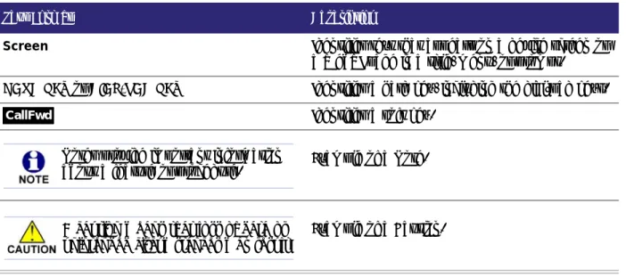
Figure 1 illustrates how the Syn248 system differs from conventional telephone systems in that calls are not coordinated by a central controller. Instead, the system uses a distributed control system over a new or existing local area network (LAN).
Figure 1. Sample System Network
blue lines = telephone
red lines = Ethernet
orange lines = audio
Installation 10
Recommended Installation Sequence
1. Prepare your site for installation. See “Site Preparation” on page 11. 2. Install the Gateway(s). See “Connecting the Gateway” on page 17.
3. Install the first Deskset. See “Deskset Installation” on page 19. This Deskset is assigned extension number 200.
4. Install the other Desksets. See “Deskset Installation” on page 19.
5. If an SB35025 Deskset is installed, connect an optional Music on Hold source and/or overhead paging system. Use the supplied audio in/out cable. Its L-shaped connector is designed to fit into the space available behind the Deskset. See “Connecting an Overhead Paging System (OHP)” on page 26 and “Connecting a Music on Hold Source” on page 28.
6. Configure the system using the WebUI. See “System Configuration” on page 35. 7. Install and register any AT&T DECT Cordless Headsets. See “Cordless Headset
Installation and Registration” on page 30. 8. Complete post-installation tasks.
Ask all users to record their user names on their Desksets.See “Name Recording
for the Auto Attendant Directory” on page 47.
Check for software upgrades and register your Syn248 system products. See
Installation 11
Site Preparation
This section describes how to prepare your site for a successful Syn248 system installation.
Network Requirements
A switched network topology is recommended for your LAN (using standard 10/100 Ethernet switches that carry traffic at a nominal rate of 100 Mbit/s). The office LAN infrastructure should use Cat.-5 (or better) cable.
The LAN connections to Syn248 devices should all be wired. However, wireless connections to other devices (such as laptops) in your office network that are not part of the Syn248 system will not impede performance.
All devices in the Syn248 system must reside on a single subnet.
A DHCP server is recommended and must be on the same subnet as the Syn248 system so that IP addresses can be auto-assigned. In most cases, your network router will have a Dynamic Host Configuration Protocol (DHCP) server that will automatically assign IP addresses to Syn248 devices in the system. By default, Syn248 assumes that this automatic assignment will occur.
If no DHCP server is present, you can assign static IPs. If you do not have a DHCP server or do not manually assign static IPs, you will not be able to access the Syn248 WebUI and/or enable automatic time updates from an NTP server. Syn248 devices will self-assign link-local IP addresses for all voice
communication in addition to any DHCP or static IPs that are assigned for management purposes. For more information, see “Appendix B: IP Addresses and Connectivity” on page 119.
Unless you want to manually set the Syn248 clock and manually upgrade Syn248 software, an Internet connection to the LAN is required.
A DNS server is recommended to resolve the path to the Internet and to the AT&T server for software upgrades.
If a routing path to the Internet is not available, the system administrator can download the upgrade files and use the WebUI to upgrade the software manually.
For users whose computers require a GigE Ethernet frame rate (a gigabit per second), use separate Ethernet connections for the Deskset and the computer. The Ethernet connection through a Deskset is limited to 100 Mbits/s.
Installation 12
Placement Considerations
Avoid placing any Syn248 component too close to the following:
Communication devices, such as television sets, DVD players, or other cordless telephones
Excessive heat sources
Noise sources, such as a window with traffic outside, motors, microwave ovens, refrigerators, or fluorescent lighting
Excessive dust sources, such as a workshop or garage Excessive moisture
Extremely low temperature
Mechanical vibration or shock, such as on top of the washing machine or workbench.
Power Considerations
Ensure that there is an electrical outlet not controlled by a wall switch within 6 feet (1.83 m) of each device location.
Syn248 Desksets are also compatible with Power over Ethernet (PoE). To use PoE, your network needs a switch that provides PoE. Using PoE simplifies your installation by eliminating the need to route separate power cords. It also allows you to protect your system from power outages by connecting an Uninterruptible Power Supply (UPS) to your PoE switch and Gateway(s). For power requirement specifications, see “Appendix C: Technical Specifications” on page 120.
Other Preparations
Before installing the Gateway and Desksets, the following preparations may need to be taken:
All telephone lines must be gathered into one access point situated no more than 9 feet (2.74 m) from the Gateway location. If you need to rewire your lines, contact your telephone service provider and request the help of a qualified technician.
You may need one or more network switches set up to ensure there are sufficient ports available for other devices in the network (such as a DSL modem). If you plan to use the emergency bypass feature on the Gateway, you will need
an analog phone.
An Ethernet port must be available within 9 feet (2.74 m) of each Deskset location. Each Deskset is capable of sharing an Ethernet port with a PC. If one Ethernet port already exists at a workstation, another port is not necessary unless you need a GigE Ethernet frame rate. If this is the case, use a separate Ethernet connection for the Deskset and the computer.
Installation 13
Assigning Telephone Lines and Extensions
This section discusses various telephone line configuration issues to consider.
Providing Limited Telephone Service During AC Power Outages
The fourth line on each Gateway is a Bypass port that works during AC power failures. If you have a telephone line plugged into LINE 4, connect a line-powered analog telephone to the RJ-11 jack labeled BYPASS for telephone service during power failures. When power is restored and the line is idle, a relay disconnects this emergency bypass line so that the bypass line cannot be used to eavesdrop on normal calls.
If your telephone lines are part of a hunt group (a telephone company feature that allows calls to a busy phone number to roll over to the next available telephone line), connect the line with your main (pilot) telephone number to Gateway LINE 4.
Analog Line Connection Order on Gateways
For outgoing calls, by default the system seizes the lowest idle LINE port numbers (as labeled on the Gateway) when users go off hook. You can also configure the automatic off-hook line selection for each extension (see “Extension Basic Settings” on page 59). If you plan not to change the default settings, telephone lines should be connected to your system with your busiest incoming line placed in the highest port number on the highest numbered Gateway (that is, Gateway #2 if you have the maximum two Gateways installed), so that incoming calls are less likely to receive busy signals. For instance, if your customer service team receives many calls, you would want to plug their phone lines into higher-numbered LINE ports.
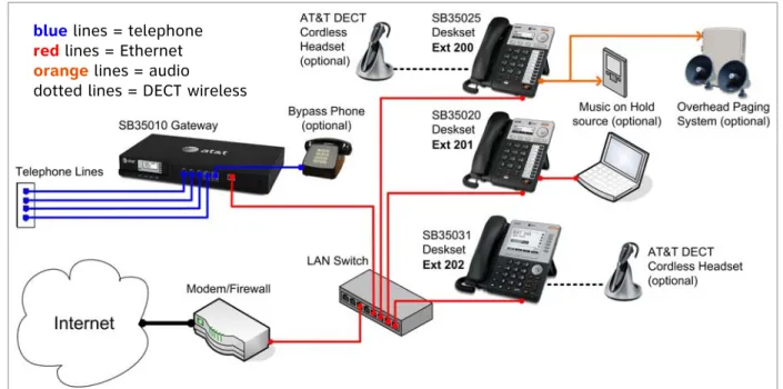
Connecting a Two-Line Wall Jack to the Gateway
If you have two phone lines coming from one wall jack, you must use a two-line adapter (or A/B splitter) as shown in Figure 2 to convert the two-line jack into two single-line jacks. Each single-line jack will then connect to a Gateway LINE port.
Figure 2. Two-line Adapter
To Wall Jack
Installation 14
Extension Assignments
The system assigns the first Deskset to join the network as extension 200. The system automatically assigns each additional Deskset an extension number in ascending order as it is connected to the LAN.
Once the Desksets are connected to the same network, they find each other through Peer-to-Peer (P2P) discovery protocols and automatically self-configure. Additional telephony and network configuration is administered through the WebUI.
Even if you disconnect a unit from the network, its extension number is reserved. If you want to remove an extension from the network permanently, you must disconnect it, then delete the extension number using the WebUI Device Management menu. See
“Deleting Devices” on page 68. Deletion ensures that the Deskset does not tie up an extension. You can also use the WebUI to change extension numbers for Desksets connected to the network.
Installation 15
Gateway Placement
You can install the Gateway in a standard 19-inch rack, on a desktop, or mount it on a wall. The Gateway must be installed within three feet of the building ground point. Install each device using the following instructions.
Rack Mounting
To mount the Gateway into a standard 19-inch rack:
1. Remove the two mounting brackets and six screws from the packing tissue. 2. Position a bracket at the front of the device and align the screw holes using the
locating indentation.
3. Insert each of the three screws into the holes provided and tighten securely. Repeat the process for the other bracket.
4. Position the chassis into the rack.
5. Insert a top mounting screw (not included) in one side and turn it several turns to establish support. Repeat for the other side.
6. Tighten the screws.
Installation 16
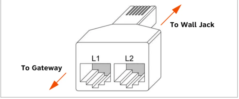
Wall Mounting
You can mount the Gateway to a wall using the two mounting slots on the bottom of the device. Ensure that the device is oriented as shown in Figure 3 to allow air to flow vertically through the ventilation holes on each side of the device.
Figure 3. Wall Mount Orientation
To mount the Gateway to a wall:
1. Install two pan-head screws (with ¼-inch diameter head) 7 ⅞ inches (20 cm) apart. The screw shaft diameter should be ⅛-inch (3.2 mm). Ensure you use anchors appropriate for your mounting surface. Leave about ⅛-inch (3.2 mm) clearance between the screw head and the wall.
2. Position the device with the mounting slot centers aligned over the mounting screws. Carefully bring the device down onto the screws.
3. Slide the device downwards so that the screws go into the mounting slots on the device. Ensure the device is secure.
Installation 17
Connecting the Gateway
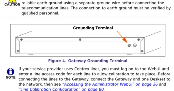
Figure 4. Gateway Grounding Terminal
Connect the telephone lines to the Gateway:
1. Remove the plastic covers from the Gateway LINE ports to be used, as shown in Figure 5.
Figure 5. Gateway Telephone Line Connections
2. Plug up to four telephone lines from the telephone wall jacks into the Gateway.
Figure 6. DSL Connection
The Gateway grounding terminal shown in Figure 4 must be connected to reliable earth ground using a separate ground wire before connecting the telecommunication lines. The connection to earth ground must be verified by qualified personnel.
Grounding Terminal
If your service provider uses Centrex lines, you must log on to the WebUI and enter a line access code for each line to allow calibration to take place. Before connecting the lines to the Gateway, connect the Gateway and one Deskset to the network, then see “Accessing the Administrator WebUI” on page 36 and
“Line Calibration Configuration” on page 80.
DC 5.1V LINE 1 LINE 2 LINE 3 LINE 4 BYPASS
LAN RESET LINE 1 LINE 2 LINE 3 LINE 4 POWER SELECT CANCEL DOWN UP + -BYPASS LINE 1 through LINE 4
If you subscribe to Digital Subscriber Line (DSL) high-speed Internet service through your telephone line, you must plug each telephone line with DSL service into a DSL filter. Then plug the DSL filter into the telephone wall jack, as shown in Figure 6.
Installation 18
Connect the Gateway to the network:
1. Connect the supplied Cat.-5 LAN cable (or a comparable substitute) from your office LAN to the Gateway LAN port.
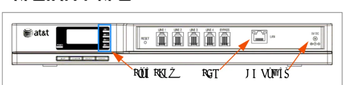
Figure 7. Gateway Power and LAN Connections
2. Plug the AC plug into an electrical outlet not controlled by a wall switch and the DC plug into the DC Power jack on the Gateway, as shown in Figure 7. Wait up to one minute until the screen lights up.
The Gateway takes about a minute to power up. The Line LEDs blink for up to 15 seconds during initialization, then turn off.
After another Syn248 device is installed, and after the Gateway has found the network and the other Syn248 device, Synchronized appears on the third line of the display as shown in Figure 8. This is the Idle screen.
Figure 8. Gateway Idle Screen, Synchronized
An IP address beginning with 169.xxx indicates there is no DHCP server on the network. Without a DHCP auto-assigned IP address (usually beginning with 192.xxx), the Syn248 devices may not show the correct time and date and you may not be able to access the WebUI to configure the system. You may have to set the time and date manually from a Deskset. See “Set Time and Date” on page 95.
LAN DC Power
Installation 19
Deskset Installation
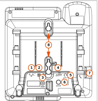
Figure 9 identifies the features on the bottom and side of the Deskset. You can install the Deskset on a desktop or mount it on a wall.
Figure 9. Deskset Connections (SB35025 Model Shown) 1. Network Port There are two LEDs next to each network port.
The green LED is on when the Deskset is connected to the network and has AC power.
The yellow LED flashes when there is network activity. 2. PC Port Intended for connecting an end-user PC to share the same
LAN connection as the Deskset.
3. Reset Button Restarts the Deskset when pressed momentarily.
Restores factory defaults when pressed and held for more than five seconds with the LAN cable disconnected.
4. Power Jack For connecting the AC adapter to the Deskset. The Deskset also supports Power over Ethernet.
5. Corded Headset
Jack For connecting a corded headset. Actual jack location may be different than shown.
6. AUX I/O Port SB35025 Deskset only — For connecting a Music on Hold source and/or a single-zone overhead paging system.
7. Handset Jack For connecting the corded handset to the Deskset base using the supplied handset cord.
8. Wall-Mount Slots See“To install the Deskset on a wall:” on page 22.
RESET 1 2 3 4 5 7 8 6
Installation 20
To attach the Desktop stand for desktop installation:
1. Select a Deskset position. The desktop setup requires the Deskset stand and provides two positions, option 1 at 45° and option 2 at 60°, as shown in Figure 10. If you use option 2, rotate the handset tab as explained in “To rotate the handset tab for wall and Deskset Option 2 installation:” on page 21.
Figure 10. Deskset Stand Options
2. Place the Deskset on a flat surface with the power and network ports facing you, as illustrated in Figure 12.
3. Place the stand, illustrated in Figure 11, on the base with the flexible tab side away from you.
Figure 11. Deskset Stand Tabs
4. Insert the solid tabs of the stand into the option 1 or option 2 slots on the base that are marked in red in Figure 12.
Figure 12. Deskset Stand Installation
Option 1 Option 2 Flexible Tabs Flexible tabs Flexible tabs Solid tabs Solid tabs Option 1 Option 2
Installation 21
5. Rotate the stand away from you until it rests against the base and you hear a click
as the flexible tabs lock into place.
To rotate the handset tab for wall and Deskset Option 2 installation:
1. Press the switch hook and slide the handset tab toward the top of the base, asshown.
2. Rotate the handset tab 180° so that the “hook” is at the top.
3. Slide the handset tab back into the base.
Switch Hook Handset Tab
Installation 22
To install the Deskset on a wall:
1. Plug the Ethernet cable into the port on the back of the Deskset. (See “To connect the Deskset to the network:” on page 24.)
2. Plug the power adapter into the jack on the back of the Deskset. Skip this step if using PoE. (See “To connect power:” on page 25.)
3. Place the Deskset base over the mounting plate as shown in . The Deskset will fit onto wall-mount screws with centers 3 ¼ inches (8.2 cm) or 4 inches (10.2 cm) apart. Most standard wall plates have screw centers 3 ¼ inches apart.
4. Slide the Deskset base down as shown in .
5. Plug the Ethernet cable into the LAN switch or wall jack.
6. Plug the power adapter into a power outlet not controlled by a wall switch. Skip this step if using PoE.
7. Make sure the handset tab is in the wall position, as described in “To rotate the handset tab for wall and Deskset Option 2 installation:” on page 21.
8. Connect the handset to the handset jack on the left side of the Deskset.
Wall-mount screws with centers 3 ¼ or 4 inches apart
Installation 23
Connect the corded handset:
1. Plug the coiled end of the handset cord into the handset jack on the left side of the Deskset.
2. Plug the end of the handset cord with the longer straight portion into the handset, then hang up.
Connect an optional corded headset:
Plug an optional corded headset or cordless headset base into the RJ-9 connector on the bottom of the Deskset, as shown.
Handset Jack on Deskset Handset Jack on Handset
Optional Headset Jack
Installation 24
To connect the Deskset to the network:
1. Plug a Cat.-5 Ethernet cable into the Network port on the back of the Deskset. 2. Plug the other end into an Ethernet wall jack that connects to your LAN switch. If there is a networked computer and no extra Ethernet wall jacks near the Deskset, then the Deskset and PC can share the same network connection.
1. Unplug the Cat.-5 Ethernet cable from your computer.
2. Plug that Cat.-5 Ethernet cable into the Network port on the back of the Deskset, as shown below.
3. Plug another Cat.-5 Ethernet cable into the PC port on the Deskset.
4. Plug the other end of the second Cat.-5 Ethernet cable into your computer.
If a GigE network is being used, a computer connected through the Deskset will be limited to 100 Mbits/s. If you require a GigE Ethernet rate, use separate Ethernet connections for the Deskset and the computer so that the computer can take advantage of the greater bandwidth.
If a PC is connected to your LAN through a Deskset, any Deskset resets and power or network interruptions will disrupt the PC’s connection to the network.
PC Network
The PC port on the Deskset is intended for connection to an end-user PC only.
Do not use the PC port to connect to a PC with a heavy bandwidth load
(such as a network server PC or a hub, switch, or router).
Do not use the PC port to extend the network. The end-user PC should be
Installation 25
To connect power:
If you are using PoE, connecting the Deskset to the network also connects the power. If you are using the supplied power adapter:
1. Plug the power adapter (blue tag) into the DC Power jack on the back of the Deskset.
2. Plug the power adapter into an outlet not controlled by a wall switch. The display screen illuminates within a minute.
If the user's computer is plugged into an uninterruptible power supply (UPS), consider plugging the Deskset into it, too. This will help prevent a computer connected to the Deskset PC port from losing its network connection during a power outage (providing that other network resources have backup power as well).
Installation 26
Connecting an Overhead Paging System (OHP)
You can connect a single-zone overhead paging system to an SB35025 Deskset using the supplied audio in/out cable. Syn248 supports one single-zone paging system per Syn248 system. If necessary, you can connect both an overhead paging system and a Music on Hold source to a single SB35025 Deskset using the supplied audio in/out cable.
Syn248 supports most OHP systems that support auxiliary audio-out connections to a PBX. You should also refer to your OHP system's product documentation for installation and configuration instructions or contact your OHP equipment provider. Some settings for the OHP may have to be changed to work with Syn248.
A single-zone paging system:
broadcasts to all overhead speakers at once. can be included in a Syn248 Paging Zone.
does not appear in the Paging Zones menu on a Deskset unless you add Overhead Page to a paging zone you create.
must be connected to the SB35025 AUX I/O port. You may need to make or buy a custom cable for the final connection to the paging system. One end of this cable must have a 1/8-inch (3.5 mm) jack to connect to the supplied audio in/out cable.
When connecting an overhead paging system, ensure that you use the supplied audio in/out cable to connect the system to the SB35025 Deskset AUX I/O port.
The supplied audio in/out cable terminates in a ring/sleeve (or ground) connection at the “Paging Output” jack. Ensure that the cable that connects between the supplied audio cable and your overhead paging system is
compatible with this configuration. The cable connector shown below would be compatible.
Ring Sleeve
Whether you are replacing a phone system and using an existing, functional OHP, or installing a new OHP, the paging system may have settings that need to be adjusted to work with Syn248.
Installation 27
To install an overhead paging system:
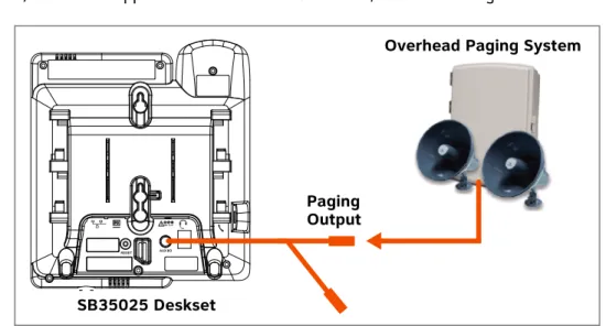
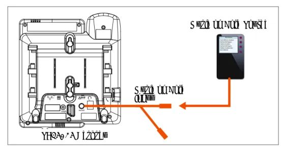
1. Plug an audio cable from the OHP device into the “Paging Output” jack of the audio in/out cable supplied with the SB35025 Deskset, as shown in Figure 13.
Figure 13. Overhead Paging System Connection
If you need to hard-wire a connection between your OHP device and the supplied audio in/out cable, you can configure a stereo audio cable as follows:
a. Remove the 1/8-inch (3.5 mm) plug from one end of the cable.
b. Strip enough shielding from the cable to expose the three wires inside.
c. Identify the Ring (Right channel) and Ground wires. Depending on the cable, the Ring wire may be red and the Ground wire may be bare/unshielded, as shown in Figure 14. You can use a voltmeter to properly identify the wires.
Figure 14. Hard-Wiring a Stereo Cable to the OHP
d. Trim the Tip (Left channel) wire to ensure it does not contact other wires or terminals.
e. Connect the Ground wire to the negative terminal and the Ring wire to the positive terminal on the OHP device.
f. Connect the other end of the hardwired cable to the “Paging Output” jack of the supplied audio in/out cable.
2. Connect the supplied audio in/out cable to the SB35025 Deskset AUX I/O port. 3. Log on to the WebUI to enable the OHP device. See “Accessing the Administrator
WebUI” on page 36 and “Overhead Paging” on page 51.
RESET
SB35025 Deskset
Overhead Paging System
Paging Output
3.5 mm stereo plug to supplied audio in/out cable
Ground Ring (Right Ch.) Tip (Left Ch.)— Do not wire to OHP
Installation 28
Connecting a Music on Hold Source
Your music on hold (MoH) source can be a streaming audio source, such as a radio or MP3 music player. The audio source must have a volume control. The volume adjustment on the audio device should be set to obtain the preferred level of music on hold within the system.
On-hold music functionality should only be used in conjunction with music specifically licensed for on-hold use. Licensed on-hold music is available from many third-party suppliers. AT&T disclaims any liability arising from the failure to obtain such a license.
When connecting an MoH source, ensure that you use the supplied audio in/out cable to connect the source to the SB35025 Deskset AUX I/O port.
The supplied audio in/out cable terminates in a tip/sleeve (or ground) connection at the “Music on Hold Input” jack. Ensure that the cable that connects between the supplied audio cable and your MoH source is compatible with this configuration. Either cable connector shown below would be
compatible.
Installation 29
To install a music on hold source:
1. Connect an audio cable with 1/8-inch (3.5 mm) jacks from your music on hold source to the “Music on Hold Input” jack of the audio in/out cable supplied with the SB35025 Deskset. See Figure 15.
Figure 15. Music on Hold Source Installation
2. Connect the supplied audio in/out cable to the SB35025 Deskset AUX I/O port. 3. Log on to the WebUI to configure the Music on Hold settings. See “Accessing the
Administrator WebUI” on page 36. The Music on Hold settings are listed under Hold
Settings in the WebUI. You must:
Enable Music on Hold.
Select the extension (Deskset) to which you have connected the music on hold source.
For more information, see “Configuring Hold Settings” on page 49.
RESET
SB35025 Deskset
Music on Hold Source
Music on Hold Input
Installation 30
Cordless Headset Installation and Registration
Install the cordless headset charger, then install and charge the battery according to the headset user’s manual.
You can register one AT&T DECT Cordless Headset to a Deskset. When a Deskset has a cordless accessory, the Deskset and headset are all part of the same extension, and only one device can be used at a time.
SB35025 Deskset Registration
To register the cordless headset:
1. On the Deskset, press (MENU), then 2, and then 6.
The Cordless Headset menu appears.
2. Remove and replace the cordless headset from its charging base.
3. Press . Registration in Progress... appears while the Deskset searches for the headset.
4. When registration is complete, Headset is registered appears. 5. Press (CANCEL). The User Settings menu appears.
The SB35020 Deskset does not support AT&T DECT Cordless Headsets.
The headset must be in the charger, fully charged and deregistered from any other device before registration can proceed. Remove and replace the cordless headset before you press Register on the Deskset.
Register
While registration is in progress, registration can be terminated by pressing (CANCEL) on the Deskset.
If the cordless headset is registered to another Deskset, it must be deregistered first. See “Deregistering a Cordless Headset” on page 32.
Installation 31
SB35031 Deskset Registration
To register the cordless headset:
1. Press (MENU), then 2, and then 5.The Cordless Headset Registration menu appears.
2. Remove and replace the cordless headset from its charging base.
3. Press . Registration in Progress... appears while the Deskset searches for the headset.
4. When registration is complete, Cordless Headset is currently Registered appears and the cordless headset ON/OFFlight turns solid blue.
5. Press . The User Settings menu appears.
The headset must be in the charger, otherwise registration cannot proceed.
Cordless Headset Registration Cordless Headset is currently Not Registered
Register Exit
Place Cordless Headset in charger. Press Register to begin process.
Quick Dial
Register
Exit
Registration can be terminated by pressing CANCEL on the Deskset. If the cordless headset is registered to another Deskset, it must be deregistered first. See “Deregistering a Cordless Headset” on page 32.
Installation 32
Deregistering a Cordless Headset
You must deregister cordless accessories before you can register them to different Desksets. If you remove a Deskset from the system, first deregister any cordless accessories.
SB35025
To deregister a cordless headset:
1. Press (MENU), then 2, and then 6.
The Cordless Headset menu appears.
2. Press . The confirmation message appears. 3. Press to confirm deregistration.
The Deskset screen displays Headset is not registered.
4. Press (CANCEL). The User Settings menu appears.
SB35031
To deregister a cordless headset:
1. Press (MENU), then 2, and then 5.The Cordless Headset Registration menu appears.
2. Press . The confirmation message appears. 3. Press to confirm deregistration.
The Deskset screen then displays Cordless Headset is currently Not Registered. DeReg
Yes
Cordless Headset Registration Cordless Headset is currently Registered
Exit
Press DeReg to deregister the Cordless Headset. Quick Dial DeReg DeReg Yes
Installation 33
The cordless headset ON/OFFlight slowly flashes.
4. Press . The User Settings menu appears.
Cordless Accessory Registration and Deregistration Time-Out
For security reasons, the registration process on both Deskset and cordless accessory terminates after the time-out period of two minutes if registration is not successful. If the registration process times out, the Deskset it displays Registration Failed and returns to the Cordless Headset menu.
If cordless headset registration fails, remove the headset from the charger and try the registration process again, beginning with Step 1, “To register the cordless headset:” on page 30 or page 31.
Cordless Headset Registration Cordless Headset is currently Not Registered
Register Exit
Place Cordless Headset in charger. Press Register to begin process.
Quick Dial
Exit
If the cordless device is registered to another Deskset, it must be deregistered first. See “Deregistering a Cordless Headset” on page 32.
Installation 34
Product Registration
In order to keep your system up to date with the latest upgrades and ensure timely warranty support, it is extremely important to register your system. To register a device, you need its MAC address.
To find a Deskset MAC address:
Press (MENU), and then press 4. Scroll down if necessary and note the MAC
Address line.
To find a Gateway MAC address:
Press SELECT, DOWN, SELECT, and then press DOWN until MAC Address appears.
To register your Syn248 system:
1. Open a new browser tab and navigate to the SMB Telephones product
registration web page.
2. Select your products, then complete the form. 3. When the form is complete, click Send.
Deskset Information Quick Dial Model No: SB35031 Status: Synchronized* IP Address: 192.168.0.10 MAC Address: 00:11:A0:11:EA:4D Serial No: GG20013043 Boot Ver: 2.7.1 P Firmware Ver: 1.3.
Exit
Use or to scroll. Press Exit when done.
System Configuration 35
C
H A P T E R
2
S
YSTEM
C
ONFIGURATION
The WebUI allows you to configure Syn248 devices and the Syn248 system. The WebUI is embedded in every SB35010 Gateway and Deskset. When you access the WebUI, you are accessing it on the device, not on the Internet.
This chapter shows you how to access the WebUI, then guides you through the settings you may have to configure to commission or to customize a Syn248 system.
This chapter also covers device management using the WebUI. As the system administrator, you will use the WebUI to delete devices from the system, change extension numbers, back up your settings, and upgrade devices.
The WebUI menus covered in this chapter include: “System Settings” on page 39
“Extension Settings” on page 59 “Device Management” on page 68 “Help” on page 81.
After completing the configuration of the system, back up the system settings. See “Back Up and Restore Settings” on page 70.
System Configuration 36
Accessing the Administrator WebUI
WebUI information for Deskset users is contained in the “Web Interface” chapter of the SB35020/SB35025 Deskset User's Guide and the SB35031 Deskset User’s Guide at
smbtelephones.att.com
.To access the WebUI and log on:
1. Ensure your computer is connected to the same IP subnet as the Syn248 system. The easiest way to ensure this is to connect your PC to the PC port on the back of a Deskset with an Ethernet cable.
2. On the Deskset, press (MENU) then 4. The Deskset Information screen appears.
3. Find the IP Address on the Deskset Information screen. 4. On your computer, open an Internet browser.
5. In the browser address bar, type the Deskset IP Address and press ENTER on your computer keyboard.
The Login page appears.
Only one person at a time should log on as the system administrator to prevent unintentional overwriting of changes.
'HVNVHW,QIRUPDWLRQ 0RGHO1R6% 6WDWXV6\QFKURQL]HG ,3$GGUHVV Deskset Information Quick Dial Model No: SB35031 Status: Synchronized* IP Address: 192.168.0.10 MAC Address: 00:11:A0:11:EA:4D Serial No: GG20013043 Boot Ver: 2.7.1 P Firmware Ver: 1.3.
Exit
Use or to scroll. Press Exit when done.
SB35031 Deskset SB35025/SB35020 Deskset
You can also use a Gateway IP address (shown in Figure 22 on page 85) to log on to the WebUI.
System Configuration 37
6. Enteradminin the Login Name field and12345in the Password field, then click
. You can change the Admin ID and password once you have logged on.
The System Information page appears.
The System Information page displays the count of Desksets and Gateways. You can
also expand the System Information page to display Detailed System Information, which lists information specific to each installed device (such as the IP Address and
Software Version).
Click topics from the navigation menu on the left side of the WebUI to see them. You view and change settings in two different types of fields: drop-down lists and entry fields into which you type information. For your security, the WebUI times out after 10 minutes. If it is idle for that time, you must log on again.
The remaining procedures in this chapter assume that you have already logged on to the WebUI as administrator.
In most cases there are multiple settings on one page. Changing a setting does
not instantly apply the new value. Click on the WebUI to save all
changes on that page.
Changes made on the WebUI are transmitted to all connected devices when applied. If changes are being made at the Deskset and WebUI simultaneously, a first-come-first-served policy applies. System configuration changes are transmitted globally when you press Save on the Deskset or click on the WebUI.
System Configuration 38
Error Handling
If you type an invalid value into one of the WebUI fields and click , the page is not saved. The WebUI displays an error message at the top of the page. The field with the incorrect value is highlighted in yellow, as shown in Figure 16. You can view a more detailed error description by resting your mouse pointer on the highlighted field. .
Figure 16. WebUI Error Indication
To view Detailed System Information:
1. On the System Information page, click .
Information specific to each installed device appears. There may be a delay as the system gathers this information.
Error Message
Invalid Entry
The Connected column indicates whether or not the listed device is
synchronized with the system, so that communication can occur. No means the device is registered with the system, but not currently powered on or detected.
System Configuration 39
System Settings
After you log on to the WebUI as the administrator with a Gateway or Deskset IP address, you can make changes to the system or to individual Desksets.
The System Settings covered in this chapter include:
Changing the System Basic Settings
To view or modify the System Basic Settings:
1. In the navigation menu at left, click Basic Settings.The System Basic Settings page appears.
2. If necessary, change the Administrator Account. The Administrator ID can be up to 16 characters long. The Administrator Password is limited to four to six digits. Values outside this range generate an error message.
3. Select the Operator Extension. Any Deskset can be designated as the system operator. The default is Extension 200. The Operator can select the current Auto Attendant menu. See “Configuring the Auto Attendant” on page 42. As well, incoming external calls are forwarded to the operator extension if the caller presses 0 (zero) after the Auto Attendant answers or when callers reach an extension’s voicemail. Deskset users can call the operator by pressing 0 from an active intercom line.
When making changes to the System Settings through the WebUI, ensure that no one is using the system. To ensure the system is idle, you might need to make the changes outside of normal office hours.
“Changing the System Basic Settings” on
page 39
“Configuring the Auto Attendant” on
page 42
“Configuring Hold Settings” on page 49 “Overhead Paging” on page 51
“Configuring Phone Line CFNA” on
page 53
“Creating, Editing and Deleting
Paging Zones” on page 55
“System Directory” on page 57 “Line Naming” on page 58
System Configuration 40
4. Set the Timer for Forwarded and Transferred Outside Calls. This sets the
Maximum Call Duration for incoming calls when they are forwarded to non-system
phone numbers, such as to cell phones. When you forward these calls, two phone lines are in use for the duration of the forwarded call — one for the incoming call and one for the call to the forwarded line — with no Syn248 user able to end the call. The default time is 30 minutes, adjustable from 15 to 120 minutes. Calls exceeding the Maximum Call Duration are dropped with no warning to the callers.
5. Enable or disable Hook Flash system-wide. When enabled, Desksets have a
soft key available when an external line is active. Pressing simulates a hook flash, which signals your telephone service provider to activate a feature. For example, hook flash may switch you to another incoming call when you hear a call-waiting tone, or enable you to create a conference call. These features may be offered as part of your phone plan. Features that use hook flash occur at the Central Office (CO) and are separate from any similar functions in Syn248.
6. Set the System Time/Date Options. You can set the system time to follow a Network Time Protocol (NTP) Server (recommended) or you can set the time and date manually.
Click Set Time by NTP Server:
a. Click Default to set the time automatically from the Internet.
Flash Flash
System Configuration 41
b. Click Custom Time Server if you have your own preferred time server, then
enter the server’s URL. c. Select your Time Zone.
d. Click Yes or No for Daylight Savings Time.
OR
To set the time and date manually, click Manual. a. Enter the current time and date.
b. Select your Time Zone.
c. Click Yes or No for Daylight Savings Time. 7. Click to save these settings or click .
System Configuration 42
Configuring the Auto Attendant
The Auto Attendant automatically answers unanswered external calls when it is set as a Call Foward–No Answer destination on the Phone Line CFNA page. See “Configuring Phone Line CFNA” on page 53. When calls are forwarded to the Auto Attendant, callers hear the Auto Attendant menu, which tells them how to use a touch-tone telephone to reach the appropriate person, operator, or extension mailbox.
There are three Auto Attendant menus available — the Default menu, a Day Menu, and a Night Menu. The Default menu instructs callers to “Enter the extension number or enter 0 for the operator.” You can select the current active Auto Attendant menu using the Deskset that is set as the Operator extension (see “Setting the Current Auto-Attendant” on page 46).
You can configure the Day Menu and Night Menu with your own voice greetings and key-press commands. You cannot customize the Default menu.
Customizing the Auto Attendant Day and Night Menus
Auto Attendant menus consist of the recordings that the callers hear and lists of actions they can take. To customize the Day and Night menus, plan what you want callers to be able to do. In preparation for recording, write down the greeting and instructions you want callers to hear when they reach each menu. See “Auto Attendant Voice Prompts” on page 45.
System Configuration 43
To customize a menu:
1. Click System Settings, then Auto Attendant. The Day Menu appears.
2. Click to record a menu voice prompt. The Auto Attendant Voice
Prompts screen appears. See “Auto Attendant Voice Prompts” on page 45.
3. Set Enable Direct Dial. Enabling Direct Dial allows callers to directly dial extensions by entering an extension number after reaching the Auto Attendant.
4. Select Enable Operator. Enabling the operator allows callers to press zero (0) to reach the operator. (The default operator extension is 200.) When Enable Operator is On, callers cannot press 0 for other actions.
5. Set the dial key values. Program an action for each digit as needed by selecting the action from each digit’s drop-down list.
If you assign dial key values that are the same as the first digit of any extension (2, for example), callers will be unable to directly dial those extensions. Instead, they will be connected to the menu action associated with that key value.
System Configuration 44
The available choices are:
None — No action.
Replay — Replays the current message.
Auto Attendant Directory — Accesses the Auto Attendant Directory, which
allows callers to spell a name, followed by the pound (#) sign. See “Name Recording for the Auto Attendant Directory” on page 47 and “Extension Basic Settings” on page 59.
<Extensions> — Sends calls directly to a specific extension. Select the extension
that callers will ring when they press a specific dial key. For example, under
Press 1, select Ext. 201. Your Day Menu recorded voice prompt might say, “To
call Graham Bell at extension 201, press 1.”
<Personal Voicemails> — Sends calls directly to a specific extension’s personal
voicemail. Select the extension’s voicemail that callers will reach when they press a specific dial key. For example, under Press 1, select Mailbox 201. Your Day Menu recorded voice prompt might say, “To leave a message for Graham Bell at extension 201, press 1.”
6. When you are done, click to save these settings or click to refresh the screen without saving the changes.
If no digit keys have been pressed five seconds after the voice prompt, the voice prompt replays. After replaying the voice prompt three times, the Auto Attendant says “Goodbye” and hangs up the call.
System Configuration 45
Auto Attendant Voice Prompts
To record Auto Attendant voice prompts:
1. Click System Settings, then Auto Attendant.2. On an Auto Attendant Day Menu or Night Menu page, click . The
Auto Attendant Voice Prompts page appears.
3. Follow the instructions on the web page to record the voice prompt. Here is an example of a script for a Day menu:
“This is the Widget Company. We are open from 9 AM to 5 PM, Monday to Friday. If you know your party's extension, dial it now. To reach someone by spelling their name, followed by the pound sign, press 1. For Sales, press 3. For Customer Service, press 4. To replay this message, press 5. To speak with the operator, press 0." The Auto Attendant menu that you configure might look like the menu shown in Figure 17.
4. Click . You return to the Auto Attendant Menu Editor so that you can add actions to the menu. If you press before you hang up, the recording is not saved.
OR
System Configuration 46
Figure 17. Day Menu Example
Setting the Current Auto-Attendant
To set the current Auto-Attendant:
1. On the Operator Deskset, press (MENU), then 5 to display the Auto-Attendant menu.
2. SB35031 Deskset — Highlight the desired menu, then press .
SB35020/SB35025 Deskset — Press
or
to select the current menu: DefaultMenu, Day Menu, or Night Menu.
3. Press to save the setting.
Set?
Auto Attendant Settings 1. Default Menu
3. Night Menu 2. Day Menu
Quick Dial
Use or to scroll or press 1-3. Press Set? then press Save.
[Set]
Save Set?
SB35031 Deskset SB35025/SB35020 Deskset
System Configuration 47
Name Recording for the Auto Attendant Directory
The administrator and individual users can create name recordings at the Desksets. When callers access the Directory through the Auto Attendant, the name recording plays to confirm the selection.
In order to create a fully functional Auto Attendant Directory, ensure that you also enter a name for every extension. See “Extension Basic Settings” on page 59.
To create consistent Auto Attendant name recordings for incoming callers, ask Deskset users to state their name slowly, clearly, and at a reasonable volume. You may also recommend that users state both their name and extension number to assist incoming callers further.
SB35020/025
To record, play, or delete a personal name:
1. Press (MENU), then 2, then 1, and then 2 to display the Name Recording menu. The and soft keys do not appear if the name has not already been recorded.
2. Pick up the handset and press . The key changes to . 3. Press when finished.
4. Press to review the recorded name or press to delete the greeting. 5. Press (CANCEL) to return to the Message Greetings menu.
SB35031
To record a personal name:
1. Press MENU, 2, and 4.The Name Recording screen appears.
2. Press 1 to display the Play/Rec Name screen.
3. Pick up the handset and press to record a personal name.
You are limited to a 10-second recording. Recording stops automatically if you exceed the limit.
Play Delete
Record Record Stop
Stop
Play Delete
System Configuration 48
4. When you are finished recording, press . The screen changes to display
and .
5. Press to review the name recording.
6. To return to the User Settings screen, press .
SB35031
To delete a name:
1. Press MENU, 2, and 4.The Name Recording screen appears.
2. Press 2. A confirmation screen appears.
3. Press to confirm.
After deleting the name recording, the extension number plays to callers when they look up your name in the Auto Attendant Directory.
Stop
Play Record
Play
Exit
System Configuration 49
Configuring Hold Settings
On the Hold Settings page, you can enable Music on Hold and create a hold
announcement for callers to hear when they are on hold. When the hold announcement and Music on Hold are disabled, callers on hold hear two short beeps every 10 seconds.
To configure Hold Settings:
1. In the navigation menu at left, click Hold Settings. The Hold Settings page appears.
2. Under Hold Music, if you have a Music on Hold source connected, click Enable. 3. Select the Port, which is the extension number of the SB35025 Deskset to which the
Music on Hold source is connected. All SB35025 Desksets installed in the Syn248 system appear in the list.
4. If you want to use a hold announcement, click Enable.
5. Enter the amount of delay before the announcement first plays to a caller on hold. 6. Enter the delay before the announcement repeats.
7. To play, record, or delete the announcement, click .
8. Follow the instructions on the Hold Announcement page to record a prompt.
OR
Click to delete the announcement.
The hold announcement does not play when placing a conference on hold, or if one of the parties drops out of the conference.
Music on Hold settings do not appear if there are no SB35025 Desksets connected to the system.
System Configuration 50
9. After hanging up and clicking , you return to the Hold Settings page.
If you press before you hang up, the recording is not saved.
OR
Click to return to the Hold Settings page without saving the changes. 10. On the Hold Settings page, click to save these settings or click to
System Configuration 51
Overhead Paging
To set up external overhead paging:
1. In the navigation menu at left, click Overhead Paging. The Overhead Paging
Configuration page appears.
2. Enable or Disable the overhead Paging. When overhead paging is enabled,
“Overhead Page” appears as an available Paging Zone member on the Create/Edit
Paging Zone WebUI page. See “Creating a Paging Zone with Overhead Paging” on
page 52 and “Creating, Editing and Deleting Paging Zones” on page 55.
3. Select the AUX I/O Port, which is the extension number of the SB35025 Deskset to which the overhead paging system is connected. All SB35025 Desksets installed in the Syn248 system appear in the list.
4. Click to save these settings or click to return to the previous page without saving the changes.
The Overhead Paging Configuration page does not appear if there are no
System Configuration 52
Creating a Paging Zone with Overhead Paging
An overhead paging (OHP) system issues a one-way broadcast to all overhead speakers. These speakers cannot be grouped into separate zones. A single OHP system can be connected to the AUX I/O port of an SB35025 Deskset. This OHP system is automatically included when you page “All Extensions”.
To create a single overhead paging zone:
1. Follow the instructions in “Creating, Editing and Deleting Paging Zones” on page 55
to either Create New Paging Zone, or View/Edit an existing Paging Zone. 2. Select Overhead Page from the Available Members list and click . 3. Click to save these settings or click to return to the previous page
System Configuration 53
Configuring Phone Line CFNA
On the Phone Line CFNA (Call Forward–No Answer) page, you can specify how to forward calls that do not get answered. You can set a CFNA destination for each telephone line connected to the Gateway.
If your telephone lines are part of a hunt group (a telephone company feature that allows calls to a busy phone number to roll over to the next available telephone line), then it is recommended to set the same CFNA destination for all lines in that group.
To configure CFNA settings:
1. In the navigation menu at left, click Phone Line CFNA. The Phone Line Call
Forward No Answer page appears.
2. Select a line. The lines are listed along with their names. See “Line Naming” on page 58.
3. Select a Call Forward–No Answer Target for the line.
Off. The line rings until the call is answered or the caller hangs up.
Voicemail. The unanswered call is directed to the selected extension’s
System Configuration 54
Extension. The unanswered call is directed to the selected extension. Note
that if the call is not answered at the extension, then the call is forwarded again according the extension’s Intercom CFNA setting.
Outside Phone Number. After selecting this, enter a telephone number.
Auto Attendant. The unanswered call is directed to the currently selected
Auto Attendant menu.
4. Select the Seconds before Forwarding, from 0 to 45 seconds.
5. Click to save the setting. The new setting appears in the CFNA Destination column at top. To configure another line, return to step 2.
System Configuration 55
Creating, Editing and Deleting Paging Zones
Use paging zones to set up extensions that can be paged as a group. For example, all extensions in the sales department could be defined as a paging zone. Any Deskset user can initiate a page to all extensions or only to the members of a paging zone. You can configure up to eight paging zones, each with one or more members. You can place every extension in a paging zone.
To create a paging zone:
1. In the navigation menu at left, click Paging Zones. The Paging Zones Summary page appears.
2. Click to create a new paging zone. The Create Paging Zone page appears.