VoIP Switch
Tenor AF
Product Guide
P/N 480-0084-00-12
Tenor and Quintum are registered trademarks. Quintum Technologies, Inc., PacketSaver, Risk Free VoIP, The Perfect Fit, are trademarks of Quintum Technologies, Inc.
NOTE:The current release of the Tenor Monitor does not support the Tenor AF Series.
This unit contains new hardware, which requires newer software. This software was installed on the unit prior to leaving the factory.
If you must downgrade the software in this unit, please visit http://ae.quintum.com/support/ rohs/ for a list of latest software patches that support this new hardware. Loading unsup-ported software will render this unit inoperable and will require physical access to this unit for recovery.
T
able of Contents
About this GuideWhat’s included? . . . 1-2 Typographical Conventions . . . 1-3 Product Guide Conventions . . . 1-3 Finding Help. . . 1-4 Chapter 1: Overview
What is the Tenor AF?. . . 1-2 Features. . . 1-4 Unique Design . . . 1-4 State-of-the-Art GUI Configuration and Network Management . . . 1-4 Easy Connect to Console . . . 1-4 Powerful System Monitoring . . . 1-4 Capabilities . . . 1-5 PacketSaver™ reduces bandwidth consumption . . . 1-5 Virtual Tie Trunk. . . 1-5 SNMP Support . . . 1-5 Call Detail Recording . . . 1-6 IVR/RADIUS Support . . . 1-6 NATAccess™. . . 1-6 Dynamic Call Routing . . . 1-7 Tenor AF Call Paths . . . 1-8 Tenor VoIP Switch (AFG200, AFG400, AFG800) Configuration . . . 1-8 Tenor VoIP Switch (AFT200, AFT400, AFT800) Configuration . . . 1-9 Tenor VoIP Switch (Tenor AFM200, AFM400) . . . 1-9 Tenor VoIP Switch (Tenor AFE400, AFE600) . . . 1-11 Advanced Features/Capabilities . . . 1-12 Call Management . . . 1-12 Dial Plan Options . . . 1-12 H.323 Gatekeeper Services . . . 1-13 SIP User Agent . . . 1-14 Chapter 2: Hardware Components
Hardware Description . . . 2-2 Front Panel LEDs. . . 2-2 Back Panel . . . 2-3
RJ-11 Cables . . . 2-7 RJ-45 Ethernet Cable (10/100) . . . 2-8 DB-9 Serial RS-232 Cable . . . 2-9 Specifications. . . 2-10 Voice/Fax . . . 2-10 PSTN/PBX Connections . . . 2-10 LAN Connection . . . 2-10 Physical . . . 2-10 Electrical . . . 2-10 Environmental . . . 2-10 Chapter 3: Installation Installation . . . 3-2 Pre-Installation Guidelines . . . 3-2 Inspect Package Contents . . . 3-2 Connect to Phone/FXS Interface . . . 3-5 Connect to Line/FXO Interface . . . 3-6 Connect to Ethernet LAN . . . 3-7 Connect to PC Console (if required, see Note) . . . 3-8 Power up the System. . . 3-9 Login without the PC’s COM port/Obtain IP Address from Ethernet . . . 3-9 Login through the PC’s COM port (if required, see note) . . . 3-10 Chapter 4: Diagnostics/Maintenance
Common Symptoms/Problems . . . 4-2 Monitor LEDs . . . 4-4 Monitor Alarms. . . 4-4 How to Read Alarms . . . 4-4 Valid Alarms . . . 4-7 Display all Alarms . . . 4-9 Display Active Alarms . . . 4-10 Display Alarm History. . . 4-10 Verify Unit Provisioning . . . 4-11 Perform Maintenance . . . 4-11 Restore Factory Defaults (including password) . . . 4-11 Reset System. . . 4-12 Change Password . . . 4-13 Change Unit Date and Time . . . 4-13
Warranty/Approvals
Quintum Limited Warranty . . . 1-3 Documentation Notice . . . 1-5 Agency Approvals . . . 1-6 FCC WARNINGS. . . 1-7 Canadian Notice . . . 1-9
What’s included?
This product guide is divided into chapters; each chapter describes a specific topic. The following chapters are included:
• About this Guide: Describes what is included in the Product Guide, including typographical
conventions.
• Chapter 1: Overview. Includes a general overview of the product, including a description of the
Tenor AF features and capabilities.
• Chapter 2: Hardware Components. Hardware description, including the front and rear panels,
as well as LEDs and required cables.
• Chapter 3: Installation. Describes how to install the Tenor AF unit, including how to connect
and power up the system.
• Chapter 4: Diagnostic/Maintenance. Describes how to troubleshoot and monitor the health of
the system.
• Glossary
• Index
Typographical Conventions
Product Guide Conventions
Certain typographical conventions are used throughout this product guide. See below.
• All commands you enter via keystrokes appear in bold (e.g., Press Enter or Press Ctrl-I).
• All text commands you enter via Telnet session or command line typing appear in italics (e.g.,
type active).
• There are three types of special text that are designed to reveal supplemental information: Note, Warning, and Caution. See below.
A NOTE provides additional, helpful information. This information may tell you how to do a certain task or just be a reminder for how-to’s given in previous sections. (i.e., For a list of valid commands at any time, type ?)
A WARNINGprovides information about how to avoid harming your VoIP equipment or other equipment (i.e., Do not stack more than 4 units together.)
A CAUTION provides information about how to avoid injury to yourself or to others (e.g., Do not install the equipment during a lightning storm).
Finding Help
Refer to the Product Guide for help. The Table of Contents and Index tells you where to find infor-mation easily.
Extensive configuration help is available from the Tenor Configuration Manager User Guide or the
Command Line Interface User Guide. Both documents are on the CDR ROM you received with
C
hapter 1: Overview
This chapter gives you a general overview of the Tenor AF, including feature descriptions and
capa-bilities. Specifically, the following topics are covered:
! A description of Tenor AF
! Features
! Capabilities
! Call Paths
What is the
Tenor AF?
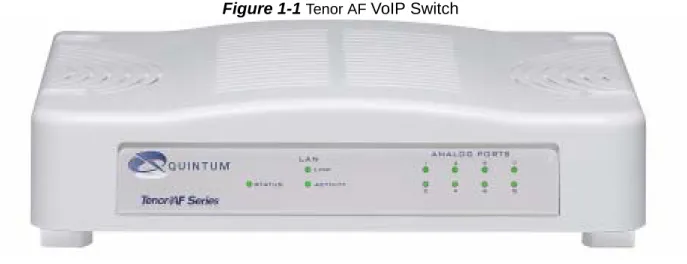
The Tenor AF is a VoIP (Voice over Internet Protocol) H.323/SIP switch that digitizes voice, fax,
and modem data, and transmits it over the IP network. Designed as a SOHO product, the Tenor AF
gives small to medium sized businesses with analog voice infrastructure an easy, cost-effective way to capitalize on the power of Voice over IP (VoIP).
The Tenor AF integrates a gateway, gatekeeper, border element, intelligent call routing, and supports
H.323/SIP all in one solution. The gateway converts regular phone calls to VoIP calls, the gate-keeper performs IP call routing functions, and the border element distributes the call routing directo-ries throughout the network. Through the FXS port, you can connect to a telephone, key system or PBX; through the FXO port, you can connect to the PSTN (through direct connection to the Central Office).
Figure 1-1 Tenor AF VoIP Switch
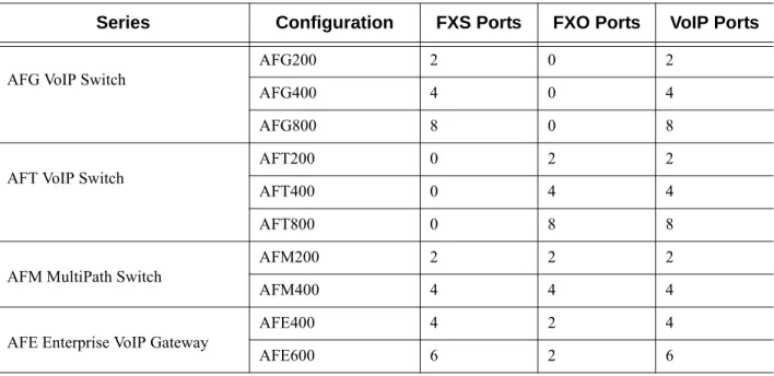
The Tenor AF is available in several configuration types:
• AFG VoIP Switch. The AFG VoIP Switch is mainly intended for applications interfacing
between the PBX and the VoIP network. The number of VoIP ports equals the number of FXS ports.
• AFT VoIP Switch. The AFT VoIP Switch is mainly intended for trunk side connections
between the PSTN and the VoIP network. The number of VoIP ports is equal to the number of FXO ports.
• AFM Multipath Switch. The AFM MultiPath Switch is mainly intended for symmetrical
mul-tipath applications, with an equal number of FXO and FXS ports. The number of VoIP channels is equal to half the number of telephony (i.e. PSTN) channels.
With its MultiPath architecture, the Tenor AF can intelligently route calls between the FXS,
FXO, and the VoIP network to achieve the best combination of cost and quality. The Tenor AF
also routes calls over IP to reduce costs, and then transparently “hops off” to the PSTN, to reach off-net locations. Calls can be routed in any direction between any of the ports.
• AFE Enterprise VoIP Gateway.The AFE VoIP Gateway is mainly intended for applications
Table 1-1 Tenor AF Configuration Types
Whichever configuration you choose, the high performance unit provides one Autosensing 10/100 Base-T connection (mode is either in half or full-duplex), along with one RS-232 serial console port connection.The unit also incorporates an intelligent call routing engine which regulates system resources and configuration while coordinating all voice traffic activity in the unit.
The unit’s simple plug-and-play embedded system architecture brings VoIP technology to your net-work without changing your existing telephony infrastructure. Your netnet-work stays as is, and the call type is transparent to the user.
Series Configuration FXS Ports FXO Ports VoIP Ports
AFG VoIP Switch AFG200 2 0 2
AFG400 4 0 4
AFG800 8 0 8
AFT VoIP Switch AFT200 0 2 2
AFT400 0 4 4
AFT800 0 8 8
AFM MultiPath Switch AFM200 2 2 2
AFM400 4 4 4
AFE Enterprise VoIP Gateway AFE400 4 2 4
Features
The Tenor AF’s specific features are explained below.
Unique Design
The Tenor AF packs powerful VoIP features into one compact unit. The Tenor can be installed
with-out upgrades to the existing voice or data network. You can install the unit in a home or office envi-ronment, without affecting the network infrastructure you already have in place. As with all Tenor products, the Tenor AF provides the power of VoIP in an easy-to-use product that takes just minutes
to get up and running.
State-of-the-Art GUI Configuration and Network Management
The Tenor AF is managed/monitored by the Tenor Configuration Manager and Tenor Monitor.
Through the Tenor Configuration Manager, you can configure all options, such as dial plans, call
routing numbers, etc. An easy-to-use Java-based installation process enables you to an install the manager and start configuring within minutes. Through the Tenor Monitor, you can monitor the
health of the system, including alarms, call detail records, etc. Both the Tenor Configuration Man-ager and Tenor Monitor provide comprehensive on-line help systems.
In addition, you can configure the unit via Command Line Interface (CLI). Through a telnet session,
you can access all configuration options, including an online help system built into the CLI, which provides help for all features and functions. Just type help at any prompt, and data about that field
will be displayed.
Easy Connect to Console
Plugging a serial cable between the unit’s RS-232 port and your PC’s console port will allow local unit management. Through the console connection, you are able to assign a static IP address. In addition, through the RS-232 port, you are able to configure the unit via the Command Line Inter-face (CLI).
Powerful System Monitoring
There are many different ways to monitor the health of the unit, including LEDs and alarms. LEDs appear on the front of the unit.The LEDs light up according to operations and alarms it is experienc-ing. Alarms indicate the unit’s operational status.
Capabilities
PacketSaver™ reduces bandwidth consumption
PacketSaver packet multiplexing technology reduces the amount of IP bandwidth required to sup-port multiple calls flowing between two endpoints. PacketSaver minimizes bandwidth usage by aggregating packet samples from multiple VoIP conversations, and packing them into a larger IP packet with a single IP header. The process removes the need to send a bulky IP header with individ-ual voice packets. This also eliminates the transmission of redundant information.
Figure 1-2 PacketSaver
Virtual Tie Trunk
The Tenor unit can emulate a tie trunk by means of the “IP Extension” feature. It provides all of the functionality of a tie trunk, including the considerable cost savings, but eliminates the need for a PBX trunk to be configured, or marked as a tie trunk. (A traditional tie trunk is a PBX-configured direct PSTN connection between two PBXs in separate locations. The virtual tie trunk bypasses the PSTN network, which results in considerable savings.) Your PBX does not need any additional con-figuration.
For example, the IP extension feature allows you to map and statically route on a one-to-one basis, each of the ports on a local Tenor to each of the ports on a remote Tenor. When the user at the remote location picks up the phone, they hear dial tone from the PBX. They get all the available PBX fea-tures, but over VoIP instead of directly. Likewise, an incoming call that would terminate otherwise onto eight telephones at the local Tenor, are instead routed via VoIP to the remote Tenor.
SNMP Support
The Tenor AF supports Simple Network Management Protocol (SNMP), the standard protocol used
to exchange network information between different types of networks.
Conventional VoIP Transmission Sends Many Redundant Packet Headers
Tenor using PacketSaver to Minimize Bandwidth Usage
Call Detail Recording
Through the Call Detail Record (CDR) feature, the Tenor AF generates a call record at the
comple-tion of each call, typically for accounting purposes. A CDR is a string of data that contains call information such as call date and time, call duration, calling party, and called party. The Tenor AF
may store Call Detail Records locally or send them to a CDR server within the network. The CDR contains sufficient information to capture billing data, which can be used to create billing reports using third party billing software. For more information about CDR, see the Billing Authentication
Handbook available on the CD you received with the unit, or at http://www.quintum.com/support.
IVR/RADIUS Support
Interactive Voice Response (IVR) is a feature of the Tenor AF that enables you to offer services to
your customers, such as Pre-paid calling cards and Post-paid accounts.
The Tenor uses the RADIUS (Remote Authentication Dial-In User Service), for authenticating and authorizing user access to the VoIP network, including ANI Authentication (Types 1 and 2). The RADIUS is a standard protocol which provides a series of standardized message formats for trans-mitting and receiving dialed information, account data and authorization codes between the network access gateway and the billing server.
For more information about CDR, see the Billing Authentication Handbook available on the CD you
received with the unit, or at http://www.quintum.com/support.
NATAccess™
NATAccess is an intelligent network address translation technology. It enables VoIP networks with
multiple H.323 endpoints to operate behind firewalls equipped with H.323 Network Address Trans-lation (NAT); this provides maximum network security. NATAccess simplifies deployment by
elim-inating the need to place the Tenor on a public IP network. Using NATAccess provides easy, secure
expansion between multiple VoIP sites. In addition, NAT technology in the Tenor permits the use of private subnets at the same time; in-house calls will never go over the public internet.
Figure 1-3 Tenor with NATAccess Deployment
Dynamic Call Routing
The Tenor AF’s intelligent call routing capabilities are state-of-the-art. The unit automatically
detects and supports three call types: voice, fax, and modem. The Tenor will first identify the call origination site—Line/FXO or Phone/FXS—and then route the call according to the parameters you have configured in the routing database.
Tenor AF Call Paths
Tenor VoIP Switch (AFG200, AFG400, AFG800) Configuration
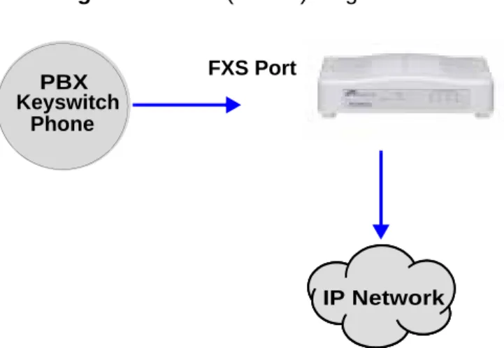
The Tenor VoIP Switch configuration is used for Phone/FXS ports connecting to the VoIP Network. The number of VoIP ports is equal to the number of FXS ports. Calls coming from the Phone/FXS interface (e.g., PBX) may be switched to the data network as a VoIP call. The routing decision made by the Tenor is based upon your configuration and the dialed number. See Figure 1-4 for an
exam-ple of a call originated from a PBX.
Figure 1-4 FXS (Phone) Originated Calls
Keyswitch Phone
PBX
IP Network FXS Port
Tenor VoIP Switch (AFT200, AFT400, AFT800) Configuration
The Tenor VoIP Switch configuration is used for trunk side PSTN (Line/FXO port) to VoIP connec-tions. Calls coming from the Line/FXO interface (i.e., PSTN) may be switched to the data network as a VoIP call. See Figure 1-5 for an example of a call originating from the PSTN.
Figure 1-5 FXO (Line) Originated Calls
Tenor VoIP Switch (Tenor AFM200, AFM400)
The Tenor MultiPath Switch Configuration is symmetrical with an equal number of Phone/FXS and Line/FXO ports. Calls are routed from the Phone/FXS, Line/FXO, or IP Network. Calls can be routed in any direction between any of the ports.
FXS (Phone) Originated Calls. Calls coming from the Phone/FXS interface (i.e. PBX) may be
switched to either the data network as a VoIP call or to the FXO interface, typically for connection to another circuit switched network such as the PSTN. The routing decision made by the Tenor is based upon your configuration and the dialed number. See Figure 1-6 for an example of a call
origi-nated from a PBX.
Figure 1-6 FXS (Phone) Originated Calls
IP Network PSTN FXO Port Keyswitch Phone PBX PSTN IP Network OR
FXO (Line) Originated Calls. A call coming from a Line/FXO interface may be switched to either
the data network as a VoIP call, a Line Circuit, or trunk typically for connection to a termination device on the user’s premises such as a PBX. The routing decision made by the Tenor AF is based
upon your configuration and the dialed number. See Figure 1-7 for an example of a call originated
from the PSTN.
Figure 1-7 FXO (Line) Originated Calls
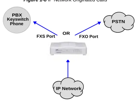
IP Network Calls. Calls coming from the IP network (data network) can be routed to the Line/FXO
or Phone/FXS interfaces. The Tenor will route calls based upon the dialed number. If the number is configured as a local phone number, the call will be sent to a Phone/FXS circuit for termination, oth-erwise the call is considered a “Hop-Off call” and the Tenor sends it out through a Line/FXO inter-face, typically connected to the PSTN. See Figure 1-8 for an example of a call originated from the
IP network.
Figure 1-8 IP Network Originated Calls
Keyswitch Phone
PBX
PSTN
FXS Port FXO Port
IP Network OR Keyswitch Phone PBX PSTN IP Network OR
Tenor VoIP Switch (Tenor AFE400, AFE600)
The Tenor AFE Enterprise VoIP Gateway is mainly intended for applications interfacing between
the PBX and the VoIP network, but it also includes two FXO ports for autoswitching PSTN back-up and 911 service provisioning. The number of VoIP ports is equal to the number of FXS ports. Calls can be routed in any direction between any of the ports.
See Figure 1-9 for an example of a call originating from a PBX.
Figure 1-9 Tenor AFE Phone/FXS Originated Call Sample
Keyswitch Phone
PBX
PSTN
IP Network
Advanced Features/Capabilities
Call Management
There are four types of routing databases you can configure: Bypass Directory Numbers (BPN), Hunt Local Directory Numbers (Hunt LDN), Hop-Off Directory Numbers (HDN) and Static Routes.
Hunt Local Directory Numbers. A Hunt group is agroup of configured phone numbers (Hunt
Local Directory Numbers, or HLDNs) assigned to a group of ports. An incoming call with a match-ing destination DN causes the Tenor to “hunt” for a port that is not in use.
Hop-Off Directory Number. A Hop-off PBX call travels over IP, and then “hops” off into the
pub-lic network (PSTN) on the destination side to reduce or eliminate pubpub-lic toll charges (also known as Leaky Area Map call). A Hop-Off Directory Number is routed over the IP to another Tenor location and then out to the Trunk circuit, possibly to the PSTN as a local call (although it does not have to be local).
Static Routes. Static Routes are used between networks and other H.323 devices that are not
regis-tered to the network through the Border Element (such as non-Quintum gateways). A static route associates endpoints (as represented by their IP address) with Directory Number patterns. Dial Plan Options
Public/Private Dial Plan Support.The Tenor AF supports public and private dial plans. A public
dial plan includes numbers which conform to the international dialing plan (E.164) of a country code + city/area code + local number. For a public dial plan, you can define the numbering plan structure for the Tenor AF to use for outgoing calls.
A private dial plan does not conform to a public dialing plan (e.g., 3 digit dialing plan); through the
Tenor AF you are able to configure the unique pattern/dialing plan structure, including number
length.
You are able to configure which dial plan to use for incoming and outgoing calls, including whether other options such as hop-off calls, will use a public or private dial plan.
User Programmable Dial Plan Support. The User Programmable Dial Plan Support (UPDP)
enables the Tenor to route calls based on the UPDP rules, which are completely customizable sets of digit sequences, such as Local, National, International, or Private Numbers.
PassThrough support for certain call types. Certain call types can be directly routed to a trunk
circuit, without using the IP. There are several routing tables you can configure via the Tenor
Con-figuration Manager to determine how the Tenor AF unit routes these types of “pass through”
num-bers. For example, you may want to configure 911 as a “bypass number”, which means that all 911 calls coming into Tenor AF from a telephone or PBX will be routed directly to a Trunk circuit
pre-sumably connected to a PSTN. Bypass calls are never routed over IP.
Hop-off PBX Calls. Hop-off numbers are phone number patterns for calls to be routed out to the
elimi-nate the toll charge.) They are entered in a Hop-off Number Directory and associated with trunks where matching calls should be sent.
Tenor AF supports those hop-off PBX calls where the destination Tenor AF is programmed to route
the call to the PSTN. The destination Tenor AF unit is configured with the phone numbers to be
“supported” for this feature. H.323 Gatekeeper Services
The Tenor AF unit’s built-in H.323 gatekeeper performs IP call routing functions, such as call
con-trol and administrative services to another Tenor AF unit, or another H.323 endpoint. The
gate-keeper’s functionality complies with the H.323 industry specifications for voice control and management.
Gatekeeper. A Gatekeeper in an H.323 network provides call control services and other services to
H.323 endpoints (i.e., gateways, terminals, and MCUs). The Tenor AF has a built-in H.323
gate-keeper which complies to the H.323 industry specifications for voice control and management. The gatekeeper performs call routing functions for calls entering and exiting a site.
The Gatekeeper performs IP call routing functions, such as Call Control Signaling and Call Authori-zation for Gateways, IP phones, and H.323 terminals. The Gatekeeper communicates with other Gatekeepers through a Border Element. When using a group of Tenor AF units, you can assign one
unit as the Gatekeeper for the network. We recommend you configure each as its own gatekeeper.
Tenor AF supports gatekeeper to gatekeeper communication using the standard LRQ (Location
Request)/LCF (Location Confirm) messaging scheme.
Zone Management. A zone is a group of H.323 defined endpoints controlled by a Gatekeeper.
End-points can be gateways (i.e., Tenor AF), terminals, and/or multipoint conferencing units (MCUs).
Endpoints establish control channels with a gatekeeper for registration, admission, and security. Call routing information about the endpoint is sent to the gatekeeper, including: IP address, unit type (gateway, terminal, or MCU) and routing information (such as phone numbers, number patterns, etc.).
A collection of zones is an administrative domain. An administrative domain provides call routing services for its zones through gatekeeper to gatekeeper messages or gatekeeper to border element messages (see below for more information).
Call Registration. When registration from an H.323 endpoint is complete and a call is originated,
the call request is sent to the gatekeeper. The call request provides the Gatekeeper with the dialed number and requests the routing information. The gatekeeper confirms the dialed number and sup-plies the endpoint with the destination IP address. For example, a Tenor AF’s gatekeeper will act as
the gatekeeper for that zone and all of the other endpoints will register with it.
Border Element. The Tenor AF’s gatekeeper uses a border element to gain access to the routing
database of the administrative domain for the purpose of call completion or any other services that involve communications with other endpoints out of the administrative domain. The border element functionality is built into the Tenor AF unit, along with the gateway and gatekeeper.
The primary function of the border element is to collect, manage, and distribute call routing infor-mation. A gatekeeper will establish a service relationship with a border element; through the border element, gatekeepers from multiple zones will be able to communicate.
A border element also establishes relationships with other border elements to route between admin-istrative domains. If a gatekeeper cannot resolve an address, it contacts the border element.
In addition, if you are using more than one Tenor unit, you can configure one of the border elements for that zone. The Tenor AF unit can use two border elements: primary and secondary. These work
together to provide redundancy and fault tolerance.
Call Services. Gatekeepers provide services such as addressing, authorization and authentication of
terminals and gateways, bandwidth management, accounting, billing, and charging. Gatekeepers also provide call-routing services. Specifically, the Tenor AF Gatekeeper provides the functions
which follow:
Address Translation. The gatekeeper translates telephone numbers into IP addresses and vice
versa. It performs Alias Address (phone number) to Transport Address (IP address) translation when an endpoint requests service. The Gatekeeper uses a translation table to translate an Alias Address (an address such as an H.323 identifier that a user may not understand) to a transport address. The translation table is updated using Registration messages.
Autodiscovery. The gatekeeper is discovered in one of the following ways: An endpoint sends an IP
broadcast called a Gatekeeper Request message (GRQ) message (which includes that correct gate-keeper name) to discover a Gategate-keeper OR the endpoint will discover a gategate-keeper by its IP address.
Routing. The gatekeeper identifies the IP address of endpoints in its administrative domain. The
gatekeeper builds a routing database from information obtained from the border element and also from gateways and H.323 endpoints.
Admissions Control. All H.323 endpoints must register and request permission to enter the
gate-keeper’s zone; the gatekeeper will confirm or deny access to the network. The gatekeeper authorizes network access and protects the integrity of the network using Admission Request (ARQ), Admis-sion Confirmation (ACF) and AdmisAdmis-sion Reject (ARJ) messages.
SIP User Agent
SIP (Session Initiation Protocol) is a signaling protocol used to establish a session on an IP network for voice control and management; it is a request-response protocol that closely resembles Hypertext Transfer Protocol (HTTP), which forms the basis of the World Wide Web. SIP re-uses many of the constructs and concepts of Internet protocols such as HTTP and Simple Mail Transfer Protocol (SMTP). The purpose of SIP is only to establish/change/terminate sessions. SIP is not concerned with the content or details of the session.
SIP is Transport layer-independent, which means it can be used with any transport protocol: UDP, TCP, ATM, etc. It is text-based, so it requires no encoding/decoding like H.323. SIP also supports user mobility, using proxies and redirecting requests to your current location.
When configured for SIP, the Tenor will act as a SIP User Agent (Endpoint) as defined in IETF RFC3261. Multiple user agents allow for separate agents to be allocated to each SIP call. It will be
able to gateway calls to and from the IP network, and Customer Premise Equipment (CPE) such as phones, PBX's, and FAX machines, or the Public Switched Telephone Network (PSTN). The Tenor SIP User Agent will work in conjunction with an external SIP proxy or redirect server to route and connect calls over SIP based networks.
C
hapter 2: Hardware Components
This chapter tells you what is contained in your hardware package. A description of each component is also included.
Specifically, the following topics are covered:
! Hardware Description
! Cables
Hardware Description
The Tenor AF is a stackable device which provides Phone/FXS and Line/FXO connections as well
as connections to the Ethernet LAN and a PC.
The unit’s front panel includes LEDs; the back panel includes connection jacks, a diagnostics but-ton, and a power adapter jack.
Front Panel LEDs
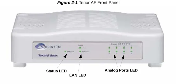
Figure 2-1 Tenor AF Front Panel
The LEDs display the health of the system. There are different types of LEDs: Status, LAN and Analog Port. A description of each is listed in Table 2-1.
Table 2-1 Front Panel LEDs Definitions
LED Label LED Color Description
Status Status Green O perational Status.
On: Unit is powered up. Off: No power.
LAN
Link Green On: Ethernet link is up.
Off: Ethernet link is down.
Activity Green Flashing: Activity (i.e,
trans-mit, receive) on the line.
Off: No activity on the line.
LAN LED
Analog Ports LED Status LED
Back Panel
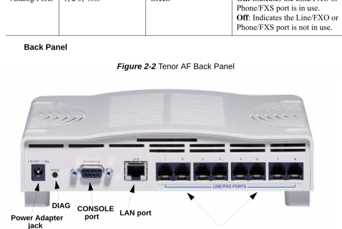
Figure 2-2 Tenor AF Back Panel
• Power Adapter jack. Connection port to external power supply.
• DIAG. Enables you to perform software diagnostic procedures.
• CONSOLE port. This RS-232 connector is used for connection to a PC’s serial port via a
DB-9 serial cable at 38400 bps 8 N 1, no flow control. The input/output signals are listed in Table 2-2.
Figure 2-3 DB-9 Female Connector Pin Order
Analog Ports 1, 2 3, 4...8 Green On: Indicates the Line/FXO or
Phone/FXS port is in use.
Off: Indicates the Line/FXO or
Phone/FXS port is not in use.
LED Label LED Color Description
Power Adapter LAN port
DIAG jack
CONSOLE port
Port Label (varies by product according to product configuration)
5 4 3 2 1 9 8 7 6
Table 2-2 Serial RS232 DB-9 Connector Pinouts
• LAN port. 10/100 Base-T Ethernet port. This port provides an RJ-45 jack for an individual
connection to a 10/100 Ethernet LAN switch or hub via RJ-45 cable; the interface is individu-ally configured with a unique IP and MAC address.
Figure 2-4 10/100 BASE-T Ethernet Port Pin Order
Table 2-3 Input/Output 10/100 Ethernet port
Pin # Function Description
1 DTR Data Terminal Ready
2 TXD Transmit Data 3 RXD Receive Data 4 CD Carrier Detect 5 GND Signal Ground 6 N.C. No Connect 7 N.C. No Connect 8 N.C. No Connect 9 N.C. No Connect
Pin # Signal Definition Color
1 TX + Transmit Data White w/orange
2 TX - Transmit Data Orange
3 RX + Receive Data White w/green
4 RSVD Reserved Blue
5 RSVD Reserved White w/blue
6 RX - Receive Data Green
7 RSVD Reserved White w/Brown
• Port Label (Phone/FXS or Line/FXO ports). For Phone/FXS, provides an RJ-11 jack for
connection to a PBX, Keyphone or analog phone. For Line/FXO, enables connection to
another piece of equipment that houses your telephone lines running to the PSTN, such as the patch panel.
Figure 2-5 RJ-11 Phone/FXS or Line/FXO Port Pin Order
Table 2-4 Input/Output RJ-11 Phone
• Port Labels. Each Phone/FXS or Line/FXO port is labeled according to the product
configura-tion.
Figure 2-6 Label according to Product configuration
Pin # Definition 1 No Connect 2 No Connect 3 Tip 4 Ring 5 No Connect 6 No Connect
Product Label Text Label Color Position on Unit
AFG200 Phone/FXS Silver with Blue Text Beneath ports 1 - 2 AFG400 Phone/FXS Silver with Blue Text Beneath ports 1 -2 & 3 - 4 AFG800 Phone/FXS Silver with Blue Text Beneath all ports
AFT200 Line/FXO Silver with Blue Text Beneath ports 1 - 2
6 5 4 3 2 1
Label example shown for AFT800. See below for label information according to product configuration.
Online/Offline Mode - AFE400/AFE600 only
If the FXS has a matching FXO port, the FXS will have online/offline capability. If the FXS goes offline, it will automatically connect to the corresponding port shown in Figure 2-7. For detailed
information about online/offline capability, see the Command Reference Guide available at http:// www.quintum.com/support.
Figure 2-7 Online/Offline Capability
AFT400 Line/FXO Silver with Blue Text Beneath ports 1 -2 & 3 - 4 AFT800 Line/FXO Silver with Blue Text Beneath all ports
AFM200 Phone/FXS Silver with Blue Text Beneath ports 1 - 2 Line/FXO Silver with Blue Text Beneath ports 5 - 6 AFM400 Phone/FXS Silver with Blue Text Beneath ports 1 - 2 & 3 - 4
Line/FXO Silver with Blue Text Beneath ports 5 - 6 & 7 - 8 AFE400 Phone/FXS Silver with Blue Text Beneath ports 3 - 4
Line/FXO Silver with Red Text Beneath ports 1 - 2 & 5 -6
AFE600 Phone/FXS
Silver with Red Text Beneath ports 1 - 2 Silver with Blue Text Beneath ports 3 - 4 Silver with Blue Text Beneath ports 7 - 8 Line/FXO Silver with Red Text Beneath ports 5 - 6
AFE400 Ports 1 2 3 4 5 6 7 8 FXS FXS FXO AFE600 Ports 1 2 3 4 5 6 7 8 FXS FXS FXO FXS
Cables
The cables listed in Table 2-5 are required to connect a Tenor AF to various interfaces. Contact
Quintum for ordering information, if necessary.
Table 2-5 Cables Supported
RJ-11 Cables
An RJ-11 to RJ-11 cable is used to connect the Tenor AF to an FXO or FXS external device. The
RJ-11 cable connector pinouts are given in this section to help you identify the proper connector to accommodate your specific networking requirements. The pin order is shown in Figure 2-8.
Figure 2-8 RJ-11 Pin Order
Figure 2-9 RJ-11 Connector Pinouts
Cable Usage
RJ-11 to RJ-11 Cable Connection to FXO/Line. RJ-11 to RJ-11 Cable Connection to FXS/Phone.
RJ-45 Ethernet cable Connection to Ethernet LAN 10/100 DB-9 Serial RS-232 Connection to PC’s asynchronous console
port. 6 1 1 6 Top View P in # C o n n e c ts to P in # 1 2 3 4 5 6 N o C o n n e c t N o C o n n e c t N o C o n n e c t N o C o n n e c t 1 2 3 4 5 6
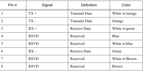
RJ-45 Ethernet Cable (10/100)
RJ-45 cable connector pinouts are given in this section to help you identify the proper connector to accommodate your specific networking requirements. The RJ-45 (ISO 8877) connector is the EIA/ TIA standard for Unshielded Twisted Pair (UTP) cable; the wiring color codes are UTP Standard Coloring. The pin order is shown in Figure 2-10.
An RJ-45 (10/100 Base-T) straight through shielded cable is used to connect Tenor AF to an
Ether-net LAN. Cable pinouts are listed in Table 2-6. Color specifications are applicable to the RJ-45 cable
provided.
Figure 2-10 RJ-45 Pin Order
Figure 2-11 RJ-45 (10/100BT) Connector Pinouts
Table 2-6 RJ-45 (10/100BT) Connector Pinouts
Pin # Signal Definition Color
1 TX + Transmit Data White w/orange
2 TX - Transmit Data Orange
3 RX + Receive Data White w/green
4 Unused Unused Blue
5 Unused Unused White w/blue
6 RX - Receive Data Green
7 Unused Unused White w/Brown
8 1 1 8 Side View Top View
Pin # Connects to Pin #
1 2 3 4 5 6 7 8 1 2 3 4 5 6 7 8
DB-9 Serial RS-232 Cable
The Serial RS-232 9-pin cable with a DB-9 male connector (with RS-232 interface) is used to con-nect the Tenor AF to your PC’s asynchronous serial port. The pin order for DB-9 male and female
connectors are shown in Figure 2-12 and Figure 2-13.
Figure 2-12 DB-9 Male Connector Pin Order
Figure 2-13 DB-9 Female Connector Pin Order
Figure 2-14 DB-9 Connector Pinouts
Table 2-7 DB-9 Connector Pinouts
Pin # Function Description Pin #
1 DTR Data Terminal Ready 1
2 TXD Transmit Data 2 3 RXD Receive Data 3 4 CD Carrier Detect 4 5 GND Signal Ground 5 6 N.C. No Connect 6 7 N.C. No Connect 7 8 N.C. No Connect 8 9 N.C. No Connect 9 1 2 3 4 5 6 7 8 9 5 4 3 2 1 9 8 7 6 P in # Con nects to P in # 1 2 3 4 5 6 7 8 9 1 2 3 4 5 6 7 8 9
Specifications
Voice/Fax
Call Routing: FXO/FXS
Coding: A-law , mu-law
Voice Algorithms: G.723.1A (5.3, 6.3 Kbps), G.726 (16, 24, 32, 40 Kbps), G.729A, G711 Fax Support: Group III at 2.4, 4.8, 7.2, 9.6, 12, 14.4 Kbps
Automatic Call Detection:Voice/Modem/Fax PSTN/PBX Connections
Interface: Analog, FXO Interface (PSTN side), FXS Interface (PBX side)
Connector: RJ-11
Ringing Cadence: Adjustable, country-dependent Maximum Loop Current: 24 mA
Ringer Equivalence Number:0-3 REN (FXO port) Ringing Frequency: Adjustable, country-dependent
Ringing Voltage: 52v RMS (1000 feet of 24 AWG wire with 3 REN LOAD) LAN Connection
LAN Support: 10/100 Mbps Ethernet
Connection Type: Autosensing of speed and mode Physical Depth: 7 ” (18.73 cm) Height: 2” (5.1 cm) Width 8 1/4 (21 cm) Weight: 1.3 lbs (0.6 kg) Electrical
Ethernet: S tandard 10/100 Base-T RJ-45 interface (IEEE 802.3) FXO/FXS: S tandard RJ-11 connectors
Console Port: RS-232/DB-9 Female
AC Power: 100-240 Volts AC, 50/60 Hz, 22 Watts Environmental
Operating Temperature: 40° to 104° F (5 - 40° C) Operating Humidity: 20% to 80% non-condensing
Altitude: -200 to 10,000 feet, or -60 to 3,000 meters Storage Temperature: 14° to 140° F, or -10° to 60° C
C
hapter 3: Installation
This chapter gives you installation instructions, as well as how to position the Tenor AF successfully
within your network.
Specifically, the following topics are covered:
! Installation
! Power up the System
! Login Without PC’s COM Port/Obtain IP Address from Ethernet
Installation
Before you begin the actual installation, review the pre-installation guidelines which follow and inspect the package contents.
Pre-Installation Guidelines
• Do not make connections from the Tenor to your public phone lines during any kind of electri-cal storm. It is possible to receive a serious injury.
• Always use an anti-static wrist strap when handling the unit.
• Do not open the unit cover. Inside parts have hazardous voltages and are extremely sensitive to static. If the unit has been opened, your warranty is void.
• Do not connect equipment in wet locations and keep away from dusty areas.
• The area must not exceed the temperature and humidity guidelines outlined in Chapter 2: Hardware Components.
• Avoid exposing the unit to excessive vibrations. Inspect Package Contents
Before you install the hardware, ensure the following components are included in your shipment: • Tenor AF
• 1 - AC Power adapter/cord • 1 - DB-9 RS-232 Serial Cable • 1 - RJ-45 to RJ45 Cable
• RJ11 to RJ11 Cables (Qty depends on model ordered) • Product Guide in CD format
If a listed component is not included in your package, contact your customer service representative. Wall Mount (Optional)
Pre-installation Guidelines
• Ensure the wall is level and stable.
• Do not attach the unit to a temporary wall.
• Ensure the wall mounting area is within cord distance of the power outlet. Required Materials
• 2 screws, #4 (diameter measure of 0.112 inches, 2.845 mm). • Drill
The Tenor AF has two wall-mount slots, which are located on the bottom of the unit. Attach the unit to the wall as follows:
1. Determine the wall area to mount the unit. With chalk or a soft pencil, mark the install area according to Figure 3-1.
Figure 3-1 Wall Mounting Dimensions
NOTE: Ensure the unit is level.
2. Drill two holes in the wall. Ensure the holes are 4.6 inches (116.84 mm) apart. See Figure 3-1.
3. Insert a screw in each hole, leaving 0.25 inches (6.35 mm) out. (The screws are not included with the unit.)
4. Line up the wall-mount slots (located on the bottom of the unit) with the 2 screws.
5. Engage the wall-mount slots over the screws and slide the unit down until the screws fit snugly onto the slots. See Figure 3-2.
Figure 3-2 Engage Wall Mount Slots over Screws in Wall
4.6” (116.84 mm)
Engage the wall mount slot over the screws inserted in the wall.
Connect to Phone/FXS Interface
Since there are many different PBX devices, key systems, fax machines and phones you can connect to the Tenor AF, the instructions which follow explain the general procedure for connecting an
RJ-11 cable (included in your package) between the Phone/FXS port and an external device. Use the phone/FXS ports for on-premise wiring only.
See Chapter 2: Hardware Components for the RJ-11 cable pinouts you can use to acquire another
cable or adapter that may be required to connect to the specific external device. NOTE: This step is not applicable if you have a configuration of all Line/FXO ports.
Figure 3-3 Connect to Phone/FXS Interface
Connect to Phone/FXS port as follows:
CAUTION: Connect the Phone/FXS ports to a telephone, fax machine, PBX, or key system only. Connecting to other devices/networks (i.e., telephone wall jack) will cause damage to the unit.
1. Plug one end of the RJ-11 cable into one of the ports on the rear of the unit labeled Phone/FXS.
See Chapter 2: Hardware Components for cable pinouts.
2. Insert the other end of the RJ-11 cable into the appropriate analog port on the PBX or key system, or into the jack on the back or underside of a phone or fax machine. For a PBX connection, see the PBX documentation port requirements for connection specifics.
3. Repeat for each RJ-11 port labeled Phone/FXS.
NOTE: For pictorial purposes, the Phone/FXS
connection is made in Port 1 and Port 2. Connection to the remainder of the ports will look identical.
PBX RJ-11 RJ-11 12ABCDEF3 45JKLMNO6 GHI 78TUVWXYZ9 PQRS *OPER0# 7910 CISCO IP PHONE i messagesdirectories settings services
Connect to Line/FXO Interface
To connect to the Line/FXO port, you can first connect the analog phone lines to another piece of equipment that houses your telephone lines running to the PSTN, such as the patch panel. If you are unsure of the installation procedures, contact the network administrator or review the documentation you received with the PBX.
See Chapter 2: Hardware Components for the RJ-11 cable pinouts you can use to acquire another
cable or adapter that may be required to connect to the specific external device. Figure 3-4 Connect to Line/FXO Interface
NOTE: If you are connecting to a punchdown block, we recommend you use solid conductor between size 22 AWG and 26 AWG, twisted pair cables.
1. Plug one end of the RJ-11 cable into one of the ports on the rear of the unit labeled Line/FXO.
See Chapter 2: Hardware Components for cable pinouts if you are making your own cable.
2. Insert the other end of the RJ-11 cable to the patch panel (or other external device) which houses your telephone lines.
3. Repeat for each RJ-11 port labeled Line/FXO.
Patch Panel RJ-11
NOTE: For pictorial purposes, the Line/FXO
connection is made in Port 1.
Connection to the remainder of the ports will look identical.
Connect to Ethernet LAN
You can use these instructions for general connection purposes only. The Ethernet hub/switch manu-facturer’s documentation should provide specific instructions for connection to another device, such as the Tenor AF.
Figure 3-5 Connect to Ethernet Hub/Switch
1. Plug one end of the RJ-45 ethernet cable into the port labeled LAN.
2. Plug the other end of the cable into one of the Ethernet hub/switch ports. If a custom cable or adapter is required, see Chapter 2: Hardware Components for the Ethernet RJ-45 10/100 cable
specifications.
Ethernet Hub/Switch
Data Network RJ-45
Connect to PC Console (if required, see Note)
NOTE: This step is not required for installation unless you would like to connect to the PC’s COM port to configure a Static IP address.
You will need to connect the Tenor AF to your workstation’s serial port through the RS-232
connec-tion (This connecconnec-tion will be used when you assign an IP address to the unit). For the following instructions, it is assumed you are connecting to a Windows PC.
Figure 3-6 Connect to PC Console (if required, see note)
1. Insert the male end of the DB-9 cable into the port labeled Console.
2. Insert the female end of the DB-9 cable into your workstation’s serial port (see your PC docu-mentation for more information about this port).
DB-9
Computer
Power up the System
Once you have all cables connected properly, you are ready to turn the system on as follows: 1. Plug the Power adapter end into the port on the Tenor AF labeled 12VDC 1.8 A.
2. Connect the other end of the Power adapter to the Power cord. 3. Plug the Power cord into the wall outlet.
Figure 3-7 Connect Power adapter
The unit will power up and the Status LED will light up and remain lit. For information about the LEDs, see Chapter 2: Hardware Components.
Login without the PC’s COM port/Obtain IP Address from Ethernet
Factory defaults are the configuration elements set on the unit new from the factory. By default, when the Tenor is shipped from the factory, the ability to support DHCP (Dynamic Host Configura-tion Protocol) is enabled. That way, you can obtain an IP address upon bootup and log into the sys-tem, without needing the COM port.
Through the LAN port on the Tenor AF, you can connect to a port on a router that is capable of
pro-viding DHCP. You can then look at the active lease table of the firewall to get an IP address. If there is no DHCP service available when you turn the unit on, the Tenor gets an IP address of
169.254.xx.xx, where xx and yy are the last two bytes of the serial number (in decimal), which
allows it to be connected to a PC with an IP on the same subnet.
Power adapter
Power cord
Login through the PC’s COM port (if required, see note)
NOTE: This step is only necessary if you wish to set a static IP address.
If you do have a COM port on your PC, when you log into a unit through the COM port at bootup, you have the option either to restore factory defaults or to configure the static IP address in the Tenor. The instructions which follow are for configuring a static IP address.
Connect through the COM port as follows:
1. Click on Start > Programs > Accessories > Communications > HyperTerminal. The Connection
Description window is displayed.
2. Enter a connection name (i.e., name for the unit such as Tenor AF NJ). Click OK.
3. Choose the serial port on your PC from the Connect Using drop down list box (i.e., Direct to
Com 1). Click OK. The COM1 Properties window is displayed. See Figure 3-8.
Figure 3-8 COM1 Properties Window
4. Select the following information: • Bits per Second: 38400
• Data Bits: 8
• Parity: None
• Flow control: None
5. Click OK.
6. Power up the unit via Power up the System. A connection to the Tenor will establish. Information
about the unit will scroll on the screen, followed by a message, "WITHIN 4 SECONDS, PRESS 'r' FOR FACTORY DEFAULTS or 'i' to SET STATIC IP".
7. Select 'i' - Set Static IP. The login prompt is displayed. The default user name/password is
admin. The current IP address, Subnet Mask, and Default Gateway are displayed. A message
asks you whether you would like to change these.
8. Type y. Follow the prompts to change the ethernet information. A message is displayed to tell
you the Ethernet interface has been successfully configured and the unit will be restarted. (If you type n, the procedure will be cancelled).
C
hapter 4: Diagnostics/Maintenance
This chapter explains the advanced topics for diagnosing problems with the unit, viewing system alarms, and performing maintenance procedures, such as upgrading the software.
! Common Symptoms/Problems
! Monitor LEDs
! Monitor Alarms
! Verify Unit Provisioning
! Perform Maintenance
Common Symptoms/Problems
Before you begin troubleshooting a potential malfunction, it is a good idea to check your basic hard-ware connections. See below.
• Ensure the AC external power adapter is firmly installed in the back panel’s power adapter port and the AC power cord is plugged into the power source.
• Verify that all RJ-45 to RJ-45, RJ-11 to RJ-11, and DB-9 cables fit snugly in each back panel jack. Faulty connections may cause a number of network interfacing or connection issues. If you suspect the problem to be on the network end, contact your Central Office to verify proper operation.
Below is a list of common symptoms and problems you may encounter. Use this list as a guideline; if your problem is not listed, use the diagnostic procedure explained in the beginning of this chapter.
Table 4-1 Common Symptoms/Problems
Common Symptom/Problem Description/Solution
Unit will not turn on. Check AC power source. Communication between Tenor AF and
the FXO or FXS cannot be established. There are several reasons why communication may not be successful. A few of the most common are listed below.
Verify correct RJ-11, RJ-45 and DB-9 cables are installed in the correct ports.
Ensure the unit is on.
Network issues may cause a number of problems. Contact the Central Office to perform test procedures. Verify that the unit is online.
Communication with Command Line Interface (CLI) cannot be established
using Telnet.
The IP address of the Tenor AF unit may be incorrect.
Check Ethernet Cable.
Verify the IP address of Tenor AF. Check the Default
Gateway Subnet Mask. These can be verified using an RS-232 connection via Console connection.
Verify network connectivity using ping from another
Communication with Ethernet Hub, or
switch cannot be established. Verify RJ-45 cable is firmly installed in the LAN port. Check MDI/MDIX configuration. Verify the mode setting on the Tenor AF matches the mode setting on
the hub/switch. Check duplex setting on the switch in which they were connected and the speed of 10 Mb/ sec or 100 Mb/sec.
Communication between the computer’s COM port and Tenor AF serial port
can-not be established.
Verify DB-9 cable is firmly placed in the unit’s con-sole port and your PC’s serial port.
Verify Terminal port settings are 38400 BPS 8N1 No Flow Control.
Tenor AF cannot receive or transmit
calls. Ensure FXO/FXS ports are working correctly.
Generate alarm list for more information.
Verify that your Ethernet connection is working. Use pin to verify.
Verify that your VoIP configuration is set correctly. Use the Tenor Configuration Manager to view
set-tings.
Verify the settings under Analog-Interface Phone and Line are correct and associated correctly.
Contact Central Office for interface issues.
Tenor AF does not have dial tone. Verify the online command is enabled through either
Command Line Interface (CLI) or the Configuration
Manager. For specific information about this
com-mand, see the Command Reference Guide at http:// www.quintum.com/support or on the Documentation
CD you received with the unit.
Monitor LEDs
LEDs monitor the health of the system; they are the first signal that the unit is not working properly or that an internal or external error has occurred. LEDs appear on the front of the unit. SeeChapter 2: Hardware Components to ensure the correct lighting of each LED. If the LEDs are not lighting at
all, check the AC power source to ensure power is being supplied to the unit.
Monitor Alarms
Alarms are brief text messages that appear on your workstation when the Tenor AF unit encounters a
problem, such as a failed interface, disconnected call, etc. Alarms help you identify where a specific problem is occurring with the Tenor AF unit.
There are two ways to view alarms for the Tenor AF unit: through the Command Line Interface (CLI) or through the Tenor Monitor. The instructions in this section are for obtaining alarms through
the CLI; see the Tenor Monitor Product Guide for information about obtaining alarms through the Tenor Monitor.
How to Read Alarms
The Alarm Manager reports alarms according to criteria such as the alarm’s severity level, line
num-ber the alarm occurred on, channel numnum-ber, etc. There are two alarm types displayed: Active Alarms and Alarm History. An Active Alarm list displays all the alarms still active on the system; these alarms have not been cleared or deleted. An Alarm History is a list of the last 100 alarms stored in the system since the last time you performed a delete operation.
Definitions for generated alarm fields appear in Table 4-2.
Table 4-2 Alarm Fields and Definitions
Field Definition Valid Entry
IP # The unit’s IP address (32 bit
address). Example:192.168.1.34.
Sequence # Internal number used to
Type (displays only if you
generate an Alarm History) The type of alarm generated. ALR = Alarm. Exceptional condition which may be a crit-ical, major, or minor condition which impacts the ability to make calls. An ALR is cleared when the abnormal condition is remedied.
CLR = Clear. This indicates an alarm that has been cleared from the system.
RPT = Report. Exceptional event which indicates a prob-lem, but which is never cleared (i.e., it is a transitory event).
Severity Level or alarm severity. 1 = Critical (complete system is affected).
2 = Major (major problem is detected).
3 = Minor (minor problem is detected).
4 = Info (Information about a minor problem).
Description A text description of the alarm; see Table 4-3 for detailed description.
Varies.
Slot # Defines which slot the alarm
occurred on. Slot 1 or 2. Slot 1 refers to the system controller functions.
Slot 2 refers to DSP functions.
Device # Defines which device the alarm
occurred on. Always device 0.
Analog Interface Defines which interface (line)
the alarm occurred on. 1 = PBX2 = PSTN
Channel # Specifies which channel the
alarm occurred on. Channel the alarm occurred on.
Date/Time Date/time the event occurred
on. Day of week: name of day.Month: Jan, Feb, March, etc. Day of month: 1 or 2 digits. Time: 6 digits (hour minutes seconds based on a 24-hour clock).
Year: 4 digits.
Valid Alarms
The following is a list of all alarm descriptions (text that appears in the Alarm Description field) for all possible alarms the system can generate. In the generated alarm list, the alarm description appears as part of the Description field.
Table 4-3 List of Valid Alarms Severity
(appears as part of severity
field)
Alarm Description
(text appears in desc field) Definition
Critical Loss of signal A loss of signal (32 consecutive zeros) at least once during a one second period.
Critical Ethernet Disconnected Ethernet cable has been disconnected from the unit, or Ethernet connectivity has been lost. No new VoIP calls will be made and existing calls will be switched to the PSTN.
Critical Call Handler not registered with
Gatekeeper The Call Handler process cannot be registered with the Gatekeeper. Critical Critical Software Error A software error has occurred that affects the
oper-ability of the complete system. Critical Tenor AF Chassis reset The chassis has reset.
Critical Configuration Data Missing Configuration is missing. Check the configuration data and add the necessary information.
Critical IVR Configuration Missing Appears if an attempt to make an IVR call has been made when a valid IP address is not configured. Occurs if an IVR call has been passed through accidently, without a real intention to use IVR for subsequent calls, while both of the servers were disabled. In order to clear the alarm, you will have to change one of the IP addresses to some value, and then disable it again.
Critical RADIUS Configuration Missing Appears when a RADIUS request is made, and one or more required configuration parameters are missing.
This alarm is cleared when the required RADIUS parameters are configured via CLI.
Critical RADIUS Server Not Responding Appears when none of the configured RADIUS servers respond.
This alarm is cleared when any of the RADIUS servers responds or the RADIUS server is disabled via CLI.
Major Major Software Error A software error has occurred that affects system signaling, interfaces, or other major operation. Major File Missing in the File Server This alarm will be reported to the system when a
particular voice prompt file is not found in the IVR Prompt Server.
This alarm applies only to the system with enabled IVR functionality.
Major Switch to other RADIUS server Appears when the current RADIUS server stops responding after three consecutive calls end in tim-eouts and another RADIUS server is configured. The Tenor will then switch to the next RADIUS server.
Major Border Element connection lost. Indicates that the Gatekeeper lost connection with the Border Element. This is cleared if the connec-tion is re-established.
Minor Call Event(s) Lost A call has failed.
Minor Missing or Incorrect Profile The configuration profile has caused a problem. Minor Minor Software Error A software error has occurred but will not affect
the operation of the complete system. Minor Remote end did not back off in a
glare situation An incoming and outgoing call went through at the same time, and the remote end call did not back off. Minor Unit resource constrained A shared resource in the unit loads the system. Minor Hardware component failed A hardware component has failed. Check all
com-ponents, hardware connections, etc.
Severity
(appears as part of severity
field)
Alarm Description
Display all Alarms
You are able to display both active alarms and an alarm history as follows: 1. Through CLI, access the Monitor prompt.
2. Type alarm. Both active alarms and the alarm history will be displayed. See section How to Read Alarms for field definitions.
Figure 4-1 Alarm sample
Minor Log RADIUS server error Displayed when the RADIUS server fails to send required data or the data sent by the RADIUS server has improper values. Incorrect information may contain the following:
RADIUS Server: Credit amount (-1) RADIUS Server: Credit minus amount RADIUS Server: Not supported currency RADIUS Server: Credit time (-1)
RADIUS Server: Credit time < 6 sec RADIUS Server: Invalid error code Informational Gatekeeper status Reports the status of the Gatekeeper. Informational Miscellaneous information Miscellaneous information about the unit is
reported. The contents of this alarm will vary. Informational Info Software Error Indicates information about a miscellaneous
soft-ware error. This does not affect system operation. Informational Glare occurred An incoming and outgoing call went through at the
same time, and the remote end call did not back off, but the situation was corrected.
Severity
(appears as part of severity
field)
Alarm Description
(text appears in desc field) Definition
IP# Sequence#Type#Severity# Desc# Slot# Device# Analog Interface# Channel# Date/Time
192.166.28.230:944:ALR:3:Border Element connection lost:0:0:0:0:TUE OCT 14 14:05:27 2005 192.166.28.230:946:RPT:4:Gatekeeper status (Gatekeeper(0.0.0.0) removed):0:0:0:0:TUE OCT 14 14:05:27 2005
Display Active Alarms
You are able to display all active alarms as follows: 1. Through CLI, access the Monitor prompt.
2. Type alarm a. The active alarms will be listed. See section How to Read Alarms for field
defini-tions. If you enter alarm without a command following it, both active alarms and the alarm
his-tory will be displayed.
Figure 4-2 Active Alarm Sample
Display Alarm History
1. Through CLI, access the Monitor prompt.
2. Type alarm h. An alarm history will be displayed. See section How to Read Alarms for field
def-initions. If you enter alarm without a command following it, both active alarms and the alarm
history will be displayed.
Figure 4-3 Alarm History Sample
IP# Sequence#Type#Severity# Desc# Slot# Device#Analog Interface# Channel# Date/Time
192.166.28.230:944:ALR:3:Border Element connection lost:0:0:0:0:TUE OCT 14 14:05:27 2005
IP# Sequence#Type#Severity# Desc# Slot# Device# Analog Interface# Channel# Date/Time
192.166.28.230:944:ALR:3:Border Element connection lost:0:0:0:0:TUE OCT 14 14:05:27 2005
192.166.28.230:945:RPT:4:Gatekeeper status (Gatekeeper(192.168.20.175) removed):0:0:0:0:TUE OCT 14 14:05:27 2005
192.168.20.175:946:RPT:4:Gatekeeper status (Gatekeeper(0.0.0.0) removed):0:0:0:0:TUE OCT 14 14:05:27 2005
Verify Unit Provisioning
An error with provisioning the Tenor AF may cause a number of problems. It may be a simple error,
such as an incorrect IP address or telephone number. See the Command Line Interface (CLI) guide
or the Tenor Configuration Manager Product Guide for configuration information.
Perform Maintenance
The following are advanced maintenance procedures you can do through the Command Line
Inter-face (CLI) or through the Tenor Configuration Manager. See the applicable user documentation you
received with the unit for detailed information. Restore Factory Defaults (including password)
Before the unit is shipped, it is set to a default factory configuration. There are several ways to restore factory defaults to the system: through the Command Line Interface (CLI), through the
Con-figuration Manager, or through the COM port.
Command Line Interface
1. Access config and type setfactory. A message will display asking whether you are sure you want
to set to factory defaults.
2. Type yes. The unit is set back to factory defaults, including the password (the default password is admin).
Configuration Manager
1. Access and log into the Tenor Configuration Manager. For more information on this step, see the
Tenor Configuration Manager Product Guide, available on the CD ROM you received with the
unit or from http://www.quintum.com/support.
2. From the main tool bar menu, select Tools > Set Factory. The Confirm Set Factory dialog box is
displayed.
3. Click Yes. Your unit’s configuration, including the password, is reset to factory defaults. A
mes-sage appears when the unit has finished being set to defaults. A dialog box tells you the unit must be reset.
PC’s COM port
You are able to change the unit back to factory defaults, including the password, after initial config-uration.
1. Click on Start> Programs> Accessories> Communications> HyperTerminal. The Connection
Description window is displayed.
2. Enter a connection name (i.e., name for the unit such as Tenor AF NJ). Click OK.
3. Choose the serial port on your PC from the Connect Using drop down list box (i.e., Direct to COM 1). Click OK. The COM1 Properties window is displayed.
4. Select the following information: • Bits per Second: 38400
• Data Bits: 8
• Parity: None
• Stop bits: 1
• Flow control: None
5. Reset the unit. Information about the unit will scroll on the screen, followed by a message, “WITHIN 4 SECONDS, PRESS ‘r’ FOR FACTORY DEFAULTS or ‘i’ to SET STATIC IP”. 6. Type ‘r’. A message asks you to confirm the factory default.
7. Type y. The configuration sets to factory defaults and the IP address related information will
remain unchanged. The login prompt is displayed. The default user name and password is
admin. Reset System
The Reset system feature enables you to reset the system, including hardware and software. You can reset through the Command Line Interface (CLI) as follows:
1. Access the CLI through a Telnet session. See the Command Line Interface (CLI) guide for more
information.
2. Access the Maintain-MasterChassis-1# prompt.
3. Type reset. You will be asked if you want to set the unit back to factory defaults.