Using Multiprotocol Label Switching (MPLS) to
Improve IP Network Traffic Engineering
Frank Gonzales, Chia-Hwa Chang, Liang-Wu Chen, Chih-Kuang Lin[email protected], [email protected],
[email protected], [email protected]
1
Introduction
The demand for multimedia applications along with rapid growth, the need for quality of service, reliability, and security have made traffic engineering an essential consideration in the design and operation of large public Internet backbone networks.1 Moreover, the rapid proliferation of the Internet has established the IP protocol suite as the predominant networking technology. With IP’s incumbent nature it is also predicted that the convergence of voice and video and data will happen over IP-based networks.2 To meet this end, the IETF (Internet Engineering Task Force) has chartered the MPLS (Multiprotocol Label Switching) working group to establish a standards based approach in developing MPLS as a means to achieve the benefits of this new technology that allows for increased performance in linking, routing and switching functions.3
MPLS attempts to enhance traffic engineering over IP-based networks by combining elements of the Open System Interconnection Model (OSI), specifically between the Link Layer (Layer 2) and the Network Layer (layer 3). This framework for an integrated layer 2 and 3 routing paradigm is referred to as label-switching.4 Packets are routed based on a size label, compared to the traditional IP network layer destination based routing. The Layer 3 protocols can be of the existing network layer protocols such as IP, IPX, Apple Talk, CLNP etc. Therefore, the label-switching scheme is referred to as ‘multi-protocol’. MPLS’s traffic engineering capabilities support existing forwarding platforms in both IP and ATM networks.
2
Purpose
The purpose of this paper will be to show that MPLS provides increased scalability, manageability, and Quality of Service (QoS) functions to IP-based networks in order to improve traffic engineering.
2.1 Defining Multiprotocol Label Switching (MPLS)
MPLS is the convergence of connection-oriented forwarding techniques and the Internet’s routing protocols.5 MPLS directs a flow of IP packets along a predetermined path across a network. The path is called a label-switched path (LSP). LSPs are similar to ATM PVCs (Private Virtual Circuits) in that they are one-way oriented. Label Switch Routers (LSR) make up the points that determine the route a packet will take. The important aspect to obtain from Figure 1 6 is that with MPLS, the physical path is not limited to what a shortest path protocol would choose.
Shortest path protocol
=
LSR Label-Switched Path (LSP)Figure 1: LSRs being used in an MPLS domain
2.2 MPLS Concept
MPLS is a forwarding scheme that evolved from Cisco's Tag Switching which uses a fixed-length label to decide packet handling. Each MPLS packet has a header that contains a 20-bit label, a 3-bit Class of Service (COS) field, a 1-bit label stack indicator, and an 8-bit Time to Live (TTL) field.7 The MPLS header is encapsulated between the link layer header and the network layer header in Point to Point Protocol and LAN Protocols. In a Frame Relay PDU it is located in the DLCI and in ATM it is located in the VPI/VCI.8 Figure 2: MPLS Concept9 Seatle (head-end) New York (tail-end) LSR LSR
MPLS
Concept
MPLS Cloud Step 2-Interior Nodes• Perform exact match on incoming label
• Lookup outgoing interface and label
• Swap labels and forward out appropriate interface
Step 1- Ingress
• Perform Layer 3 Lookup • Map to Forwarding
Equivalence Class (FEC) • Attach label and forward
out appropriate interface according to FEC
Step 3- Egress
• Pop off label
• Perform Layer 3 lookup • Forward according to L3
lookup
IP Packet LSR - Label Switch Router IP Packet w / label LER - Label Edge Router
While MPLS provides a method to set up explicit paths and forward traffic on them, it does not address the issue of how to find paths with constraints. Routing protocols as currently defined typically only advertise reachability information along with an administrative cost for the links. To enable the computation of routes with constraints, the IETF is working on extending the commonly used Interior Gateway Protocols (IGP) – Open Shortest Path First (OSPF) and Intermediate System – Intermediate System (IS-IS) -- to carry additional information about links to provide better QoS to avoid congestion and scalability problems.10
3
Traffic issues with IP
Issues that affect IP relate directly to its inability to provide traffic control as it relates to the issues of scalability, manageability and quality of service.
3.1 Traffic Control
A drawback of the present-day Internet is the complete lack of traffic management; all traffic receives best-effort service, and there is no way to predict a priority or guarantee the QoS (quality of service) that will be received by a particular traffic flow.11 Route selection is based on shortest path computations using simple additive link metrics. This approach is highly distributed and scalable, but flawed. The flaw is that these protocols do not consider the characteristics of offered traffic and network capacity constraints when making routing decisions. This results in subsets of network resources becoming congested, while other resources along alternate paths remain underutilized. This type of congestion problem is a symptom of poor resource allocation, and is an issue that traffic engineering specifically attempts to rectify through MPLS.12
4
Scalability
Normal IP unicast routing is destination based. At each router a packet is forwarded based solely on its destination address. This happens regardless of the source of the packet. At each router, flows to a destination are thus aggregated. From a routing scalability perspective, this is very desirable. Maintaining routes on a source-destination simply isn’t scalable.13
4.1 Current Forwarding Techniques
IP networks use a routing hierarchy that consists of autonomous systems (ASs) running an Interior Gateway Protocol (IGP) routing protocol and reachability across ASs conveyed using an Exterior Gateway Protocol (EGP). In IP networks, the most common IGP routing protocols used by service providers are Open Shortest Path First (OSPF) and integrated Intermediate System-Intermediate System (IS-IS). The Border Gateway Protocol (BGP-4) is almost exclusively used as the EGP. For reasons of scalability the network may be broken up into smaller administrative domains, thus introducing another level of hierarchy within the AS. Outside this domain reachability information may be aggregated, and is further aggregated when distributed across ASs. At the lowest level in
the routing hierarchy, IGP routing protocols are used to distribute information about all links in the network. Each router then uses this information to compute the shortest path to every possible destination in the network using a shortest path algorithm. In this manner each router makes an autonomous decision about how to forward a packet, and forwarding proceeds in a connectionless way at every hop. The above approach works fine in networks with sparse topology. In a network with a richly connected topology, this approach may cause an imbalance of network load. Links that do not happen to be on a shortest path tree will remain underutilized.14
The key architectural principle of MPLS is a clean separation of control and forwarding. This separation enables effective service integration including QoS transparency between service layers. MPLS’s simple label-switching paradigm applies to all traffic. Labels can be used to implicitly route packets as in native IP forwarding or they can be used to explicitly route packets in the same way as an ATM Virtual Circuit.15
5
Quality of Service & Manageability
5.1 Integrated Service and RSVP
Integrated services (IntServ) and the Reservation Protocol (RSVP) were developed as a solution to provide per-flow signaling and traffic management support. However, the acceptance and deployment of the IntServ model has been slow due in part to its scalability problems stemming from requiring periodic refreshing of the reservations of all flows. The problems with the Integrated Services architecture are:
- The amount of state information increases proportionally with the number of flows. This places a huge storage and processing overhead on the routers. Therefore, this architecture does not scale well in the Internet core.
- The requirement on routers is high. All routers must have RSVP, admission control, MF classification, and packet scheduling.
- Ubiquitous deployment is required for guaranteed service. Incremental deployment of load service is possible by deploying controlled-load service and RSVP functionality at the bottleneck nodes of a domain and tunneling the RSVP messages over other parts of the domain.16
5.2 Differentiated Services
More recently, the IETF has been working on the standardization of Differentiated Services (DiffServ), which overcomes the scalability problems of the RSVP/IntServ approach by not requiring maintenance of per-flow state in the network. Therefore, Differentiated Services is essentially a relative-priority scheme.17
Differentiated Services is significantly different from integrated services. First, there are only a limited number of service classes indicated by the DS field. Since service is allocated in the granularity of a class, the amount of state information is proportional to the number of classes rather than the number of flows. Differentiated Services is therefore more scalable. Second, sophisticated classification, marking, policing, and shaping operations are only needed at the boundary of the networks. ISP core routers
need only to have behavior aggregate (BA) classification. Therefore, it is easier to implement and deploy differentiated services.
Diffserv, for example, takes the IP TOS (type of service) field, renames it the DS byte, and uses it to carry information about IP packet service requirements. It's strictly a Layer 3 proposition and makes no assumptions about the underlying transport.
MPLS, on the other hand, specifies ways that Layer 3 traffic can be mapped to connection-oriented Layer 2 transports like ATM and frame relay; it adds a label containing specific routing information to each IP packet and allows routers to assign explicit paths to various classes of traffic. It also offers capabilities not directly related to QOS (quality of service), like traffic engineering techniques that can boost IP routing efficiency.18
5.3 How MPLS Adds Value
5.3.1 Label Switched Paths (LSP)
There are two kinds of LSPs (label switched path) based on the method used for determining the route: control-driven LSPs (also called hop-by-hop LSPs), and explicitly routed LSPs (also referred to as constraint-based routed LSPs, CR-LSPs).
Table 1:Comparison-Hop-by-Hop vs. Explicit Routing
Category Hop-by-Hop Explicit Routing
Topology Distributes topology awareness
Centralized topology awareness (in ingress node)
Path management No path
setup/teardown/refresh required
Path
setup/teardown/refresh required
Routing protocol Automates routing using industry standard
protocols (e.g. OSPF, ISIS) Requires manual provisioning, or creation of new routing protocol Path and rerouting Reroute on failure impacted by convergence time of routing protocol
Backup paths may be pre-provisioned for rapid restoration Routing flexibility Existing routing protocols are
destination prefix based
Operator has routing flexibility (policy-based, QoS-based) Traffic engineering Difficult to perform traffic engineering, QoS-based routing
Easily used for traffic engineering
A comparison of the two kinds of LSPs is depicted in Table 1.19 Having two kinds of LSPs allows for flexibility in path setup options. They include strict and loose CR-LSPs, as well as the option to pin loose segments of a path. These capabilities allow the network operator to either specify the complete path (nodes and interfaces) a LSP traverses (strict CR-LSP), or request that a portion of the route be set up automatically based on the default IGP routing protocol (loose CR-LSP). The operator may also want to pin a loose explicit path to ensure that the path doesn't change once it has been set up.20
To set up a hop-by hop LSP, the Label Distribution Protocol (LDP) has been proposed by IETF MPLS working group as the control protocol. When CR-LSP is required for traffic engineering purposes, two approaches have been debated in the MPLS working group, namely, extending the capabilities of the LDP protocol to include explicit paths via CR-LDP and extensions to the RSVP protocol.21 The extensions to existing routing protocols coupled with MPLS signaling provide powerful constructs for implementing traffic engineering in ISP networks
.
Table 2: Comparison of RSVP and CR-LDP
Category CR-LDP RSVP Transport mechanism Transport on TCP (reliable) Raw IP packets (unreliable) State management
Hard state; allow it to scale as the number of ER-LSPs increases in the network
Soft state; needs per-flow refresh
management; scalability problem when the number of paths is increased on a node, due to the refresh messages to keep the soft-state for each path
Messages required for LSP setup and maintenance
Request and Mapping Path, Resv, and ResvConf; Unnecessary message overhead in RSVP results from soft state management Architecture Base architecture Based on LDP developed for MPLS
Based on RSVP, but may require major changes to the basic protocol to improve its scalability Signaling of Qos and traffic parameters
Can signal DiffServ and ATM traffic classes Extendable; currently based on IntServ traffic classes Types of CR-LSPs
Strict, loose, and loose pinned
Strict and loose; no pinning; Pinning, gives stability control over the loose segment Modes of label
distribution and LSP setup
Easy to support all modes since ER-LDP is based on LDP
Only downstream on demand; need to run both RSVP and LDP for other modes; such as downstream-unsolicited LSPs;
Two signaling systems complicates network control Path preemption Supported Supported Failure notification
Reliable procedure Unreliable procedure
Traff ic engin eerin g featu res
Failure recovery
Global and local repair
Global and local repair; local repair done using fast-reroute which requires
precomputing alternate paths at every node
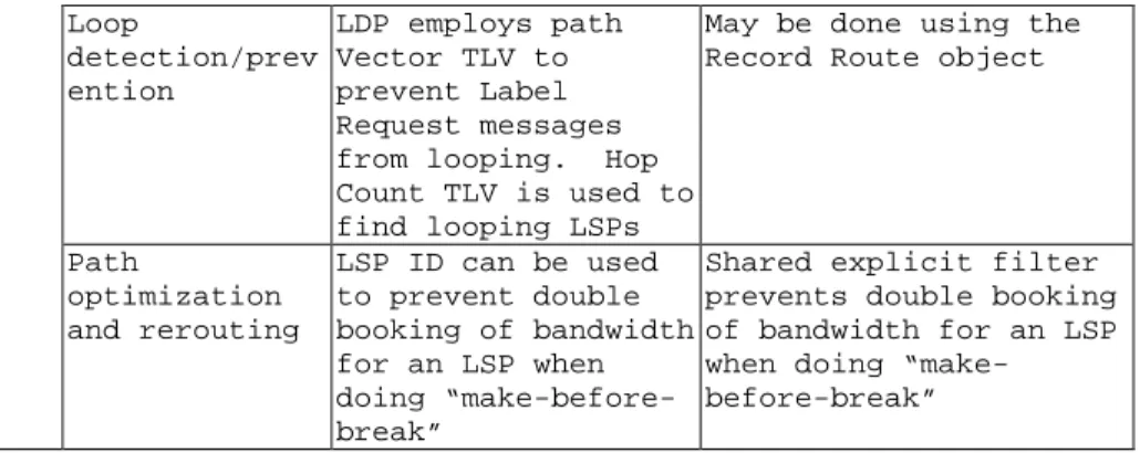
Loop detection/prev ention LDP employs path Vector TLV to prevent Label Request messages from looping. Hop Count TLV is used to find looping LSPs
May be done using the Record Route object
Path optimization and rerouting LSP ID can be used to prevent double booking of bandwidth for an LSP when doing “make-before-break”
Shared explicit filter prevents double booking of bandwidth for an LSP when doing “make-before-break”
In comparing the two signaling approaches (Table 222) for MPLS-based traffic engineering it can be seen that both RSVP and CR-LDP have similar signaling capabilities. However CR-LDP is considered be superior particularly because it uses TCP, a proven and well-optimized reliable transport mechanism, for its signaling messages. This ensures dependable operation of the protocol even in the presence of network failures and congestion. The RSVP approach, on the other hand, requires many modifications to existing RSVP mechanisms in order to improve its scalability and dependability. These modifications are currently under development in the MPLS Working Group.23
6
MPLS and ATM
6.1 Why not the IP Overlay Model
The Overlay model is a technique that was applied, prior to MPLS, to circumvent some of the limitations of IP systems regarding traffic engineering. The basic idea is to introduce a secondary technology, with virtual circuit and traffic management capability (e.g., ATM), into the IP infrastructure in an overlay configuration. The virtual circuits of the secondary technology serve as point to point links between IP routers. Figure 3 24 shows the overlay model with ATM switches at the core surrounded by an epidermis of IP routers logically interconnected by ATM permanent virtual connections (PVCs).
Figure 3: MPLS eliminates the “n-squared” problem IP over MPLS IP over ATM VCs
The overlay approach extends the design space and allows arbitrary virtual topologies to be defined and superimposed onto the physical network topology. The overlay model also permits estimation of a rudimentary traffic matrix from statistics on the PVCs that interconnect routers. Traffic engineering can also move traffic from overloaded links to relatively underutilized links by changing the designated transit lists (DTLs) of a subset of PVCs.25
There are fundamental drawbacks to the IP over ATM overlay model. Perhaps the most significant problem is the need to build and manage two networks with dissimilar technologies. The overlay model also increases the complexity of network architecture and network design. Reliability is also a concern because more network elements now exist in series on the routed path. Scalability is another issue because the number of adjacencies in the overlay graph generally increases quadraticlly with the number of routers, thereby increasing the CPU and network resource consumption associated with routing. Other issues include; the quantization and encapsulation overhead associated with ATM. The technical difficulties inherent in developing microelectronics that perform segmentation and reassembly (SAR) at very high speeds (OC-48c and above), and the possibility of routing instability in the IP domain induced by multiple PVCs failures following a single interswitch link impairment in the ATM core.
The trend, therefore, is to evolve core IP networks away from the overlay model and toward more integrated solutions. This evolution is now possible because of developments in MPLS and recent advances in high-performance gigabit/terabit routers and optical internetworking systems. Figure 426 presents the expected technology layer evolution of core IP networks from IP over ATM over SONET over fiber to IP with MPLS over SONET over DWDN; and, finally, to IP with MPLS over an adaptation layer interfacing with a versatile optical transport network (OTN).27
IP
ATM IP and MPLS IP and MPLS SONET SONET Adaptation layer
Fiber DWDM Optical transport network
(a) (b) (c)
Figure 4: Technology layer evolution.
6.2 MPLS in ATM Network
Conventional IP networks may be built by routers whose link technology is based on ATM. The MPLS technology enables node products to use ATM switches for the forwarding function. Label switch router (LSR) nodes of this kind consist of an MPLS control component (LSR-CC) and an ATM switch. The LSR-CC handles network-layer functionality, such as routing protocols, and label-management functions, which include
the label-distribution protocol. The forwarding information base and the label information base also compose part of the LSR-CC.
An ATM connection is set up for each label-switched path. The labels are used as virtual-channel-identifier (VCI) values, as virtual-path-identifier (VPI) values, or both, on each link along the path. When the upstream and downstream label-FEC binding is complete for a label-switched path, the LSR-CC can request a corresponding ATM connection through its node between upstream and downstream label or virtual channel identifier. While this is performed in the nodes along the path, the ATM connection is set up from the ingress to the egress label-edge routers along the label-path are required to perform layer-3 forwarding.
Label-switched paths are typically point to point (mp-p) paths. In a multi-protocol label switching ATM network, this translates into multipoint to point connections without interleaving cells from different frames—a facility called virtual connection merging. This type of connection has not yet been defined in standards. The present generation of ATM switches will use point to point label switched paths from each ingress node. As virtual connection merging is introduced, the scalability of multiprotocol label switching ATM will improve.
6.2.1 Label Stacks and Tunnels
To allow label-switched paths to core one or more autonomous systems, the MPLS architecture provides a mechanism for tunneling an inter-domain label-switched path between two border routers through an intra-domain label-switched path. The tunnel LSP is set up via intra-domain routing mechanisms, such as OSPF, whereas the tunneled inter-domain label-switched path is set up via the inter-inter-domain routing functions in the border routers. While in transit through the tunnel, the MPLS packet header contains a stack of two labels: one for the intra-domain routing, and one for carrying the inter-domain label through the tunnel. In multiprotocol label switching ATM networks, the tunnel label is mapped onto the VPI field and the inter-domain label is mapped onto the VCI field. The core routers of the autonomous systems switch the virtual paths for the tunnel LSPs, and the border nodes switch the virtual channels.
7 Conclusions
MPLS’s network-layer scalability and integration of Layer 2 switching and Layer 3 routing have really provided the solution for the Internet traffic problem. MPLS has many advantages for traffic engineering. It increases network scalability, simplifies network service integration, offers integrated recovery and simplifies network management, design and operation. MPLS has a greater chance of success and implementation because it is IETF standards-based and builds on the lessons learned from previous multilayer switching solutions and has been adopted by many routing protocol vendors.
From a service and cost perspective MPLS allows ISPs to deliver new services that are not readily supported by conventional IP routing techniques. This base technology (label switching) is expected to improve the price/performance of network layer routing
and provide greater flexibility in the delivery of new routing services without changing the forwarding paradigm.
Lastly, a significant attribute is that MPLS is specifically designed to run over any link-layer technology, hence the name Multiprotocol Label Switching. This attribute assists in the migration to an optical Internet based on SONET/WDM and IP/WDM infrastructures.28
Feedback
The majority of our peer feedback was based on the technical nature of our paper. Many felt that we needed approach the subject from a more interdisciplinary approach and yet others felt that it was fine as is. Our presentation was perhaps to busy and technical but given the nature of our paper and research we did we decided to deliberately keep it at the technical level we did. For those interested in obtaining a copy of our presentation for follow-on research you may contact and one of us listed at the top of the paper.
Some MPLS Terminology:
Edge Label Switch Router (Edge LSR) – The edge device that performs initial packet processing and classification and applies the firs label. This device can be either a router or a switch with built-in routing.
Label Switch Router (LSR) – The core device that switches labeled packet according to precomputed switching Tables. It can also be a switch or a router.
Label Distribution Protocol (LDP) – Provides communications between edge and core devices. It assigns labels in the edge and core devices to establish Label Switched Paths (LSPs) in conjunction with routing protocols such as OSPF, IS-IS, Enhanced Interior Gateway Routing Protocol, or BGP.
Label Switched Path (LSP) -- Path defined by all labels assigned between end points. And LSP can be dynamic or static.
Label – A label is a header used by an LSR to forward packets. The header format depends upon network characteristics. In router networks, the label is a separate, 32-bit header. In ATM Networks the label is placed into the virtual channel identifier/virtual path identifier (VCI/VPI) cell header. In the core, LSRs read only the label, not the packet header. One key to the scalability of MPLS is that labels have only local significance between tow devices that are communicating.
Cited References
1
Awduche, Daniel O. “MPLS and Traffic Engineering in IP Networks.” IEEE Communications Magazine, Dec 1999: 42-47.
2 Ghanwani, Anoop, Bilel Jamoussi, Don Fedyk, Peter Ashwood-Smith, Li Li, Nancy Feldman. “Traffic
Engineering Standards in IP Networks Using MPLS.” IEEE Communications Magazine, Dec 1999: 49-53.
3 “Multiprotocol Lable Switching (MPLS)”, 15 Jan 2000
http://www.ietf.org/html.charters/mpls-charter.html
4 van der Zee, Martin. “Quality of Service Routing.” Ericsson, July 1999: 27-39. 5
Armitage, Grenville. “MPLS: The Magic Behind the Myths.” IEEE Communications Magazine, Jan 2000: 124-131.
6 Semeria , Chuck. Traffic Engineering for the New Public Network. January 1999. 29 Jan 2000
http://www.juniper.net/techcenter/techpapers/TE_NPN.html
7 Xiao, Xipeng and Lionel M. Ni, “Internet QoS: A Big Picture.” IEEE Network, Mar/Apr 1999: 8-18 8
Rosen, Eric C. Label Stack Encoding. September 1999, 27 Feb 2000. http://www.ietf.org/internet-drafts/draft-ietf-mpls-label-encaps-07.txt
9 N+I 99 Atlanta InteropNet Labs Update, Washington, DC, November 11, 1999, 4 Feb 00.
http://www.mpls.interop.net/confstuff/atl99/interop/sld005.htm 10 Ghanwani, 50. 11 Ibid. 12 Awduche, 42. 13
Swallow, George. “MPLS Advantages for Traffic Engineering,” IEEE Communications Magazine, Dec 1999: 54-57. 14 Ghanwani, 49. 15 Swallow, 54-55. 16 Xiao, 10. 17 Ibid.
18 Ashley Stephenson, “Read the Label,” Post date N/A. 21 November, 1998
http://www.data.com/issue/981121/quality.html
19
N+I 99 Atlanta InteropNet Labs Update, Washington, DC, November 11, 1999, 4 Feb 00. http://www.mpls.interop.net/confstuff/atl99/interop/sld015.htm
20 Ghanwani, 51.
21 Li, Li, Nancy Feldman, Paul Doolan, Juha Heinanen, Andrew Malis and Liwen Wu, “IP Traffic
Engineering Using MPLS Explicit Routing in Carrier Networks: Between the Signaling Approaches—CR-LDP and RSVP,” Post date N/A. 29 Jan 2000.
http://www.nortelnetworks.com/products/announcements/mpls/source/collateral/whitepaper.html
22 Li, 51. 23 Ghanwani, 52. 24
Ashwood-Smith, Peter, Bilel N. Jamoussi, “MPLS Tutorial”, 1999, Nortel Networks, 7 Feb 00.
25 Awduche, 44. 26 Ibid.
27 Awduche, 45. 28
Semeria
Other references used
-Delivering New World Virtual Private Networks with MPLS, 13 May 1999, 13 Jan 2000
http://www.cisco.com/wrap/public/cc/cisco/mkt/servprod/dial/tech/mpls_wi.htm
-Li, Tony, “MPLS and the Evolving Internet Architecture,” IEEE Communications Magazine, Dec 1999:38-41.
-Masud, Sam, “MPLS Special Delivery.” Telecommunications Magazine, Oct 99: 22-28
-Viswanathan, Arun, Nancy Feldman, Zhen Wang, Ross Callon, “Evolution of Multiprotocol Label Switching, IEEE Communications Magazine, May 1998: 165-172