ETSI TS 136 300
V8.12.0
(2010-04)
Technical Specification
LTE;
Evolved Universal Terrestrial Radio Access (E-UTRA)
and Evolved Universal Terrestrial Radio
Access Network (E-UTRAN);
Overall description;
Stage 2
(3GPP TS 36.300 version 8.12.0 Release 8)
Reference
RTS/TSGR-0236300v8c0
Keywords
LTE
ETSI
650 Route des Lucioles
F-06921 Sophia Antipolis Cedex - FRANCE Tel.: +33 4 92 94 42 00 Fax: +33 4 93 65 47 16
Siret N° 348 623 562 00017 - NAF 742 C Association à but non lucratif enregistrée à la
Sous-Préfecture de Grasse (06) N° 7803/88
Important notice
Individual copies of the present document can be downloaded from:
http://www.etsi.org
The present document may be made available in more than one electronic version or in print. In any case of existing or perceived difference in contents between such versions, the reference version is the Portable Document Format (PDF). In case of dispute, the reference shall be the printing on ETSI printers of the PDF version kept on a specific network drive
within ETSI Secretariat.
Users of the present document should be aware that the document may be subject to revision or change of status. Information on the current status of this and other ETSI documents is available at
http://portal.etsi.org/tb/status/status.asp
If you find errors in the present document, please send your comment to one of the following services:
http://portal.etsi.org/chaircor/ETSI_support.asp
Copyright Notification
No part may be reproduced except as authorized by written permission. The copyright and the foregoing restriction extend to reproduction in all media.
© European Telecommunications Standards Institute 2010. All rights reserved.
DECTTM, PLUGTESTSTM, UMTSTM, TIPHONTM, the TIPHON logo and the ETSI logo are Trade Marks of ETSI registered for the benefit of its Members.
3GPPTM is a Trade Mark of ETSI registered for the benefit of its Members and of the 3GPP Organizational Partners.
LTE™ is a Trade Mark of ETSI currently being registered
for the benefit of its Members and of the 3GPP Organizational Partners.
Intellectual Property Rights
IPRs essential or potentially essential to the present document may have been declared to ETSI. The information pertaining to these essential IPRs, if any, is publicly available for ETSI members and non-members, and can be found in ETSI SR 000 314: "Intellectual Property Rights (IPRs); Essential, or potentially Essential, IPRs notified to ETSI in respect of ETSI standards", which is available from the ETSI Secretariat. Latest updates are available on the ETSI Web server (http://webapp.etsi.org/IPR/home.asp).
Pursuant to the ETSI IPR Policy, no investigation, including IPR searches, has been carried out by ETSI. No guarantee can be given as to the existence of other IPRs not referenced in ETSI SR 000 314 (or the updates on the ETSI Web server) which are, or may be, or may become, essential to the present document.
Foreword
This Technical Specification (TS) has been produced by ETSI 3rd Generation Partnership Project (3GPP).
The present document may refer to technical specifications or reports using their 3GPP identities, UMTS identitiesor GSM identities. These should be interpreted as being references to the corresponding ETSI deliverables.
The cross reference between GSM, UMTS, 3GPP and ETSI identities can be found under http://webapp.etsi.org/key/queryform.asp.
Contents
Intellectual Property Rights ... 2
Foreword ... 2
Foreword ... 10
1 Scope
... 11
2 References
... 11
3 Definitions,
symbols and abbreviations ... 12
3.1 Definitions ... 12 3.2 Abbreviations ... 12
4 Overall
architecture ... 15
4.1 Functional Split ... 15 4.2 Interfaces ... 17 4.2.1 S1 Interface ... 17 4.2.2 X2 Interface ... 174.3 Radio Protocol architecture ... 17
4.3.1 User plane ... 18 4.3.2 Control plane ... 18 4.4 Synchronization ... 19 4.5 IP fragmentation ... 19 4.6 Support of HeNBs ... 19 4.6.1 Architecture ... 19 4.6.2 Functional Split ... 20 4.6.3 Interfaces... 21
4.6.3.1 Protocol Stack for S1 User Plane ... 21
4.6.3.2 Protocol Stacks for S1 Control Plane ... 22
5
Physical Layer for E-UTRA ... 23
5.1 Downlink Transmission Scheme ... 25
5.1.1 Basic transmission scheme based on OFDM ... 25
5.1.2 Physical-layer processing ... 25
5.1.3 Physical downlink control channel ... 26
5.1.4 Downlink Reference signal ... 26
5.1.5 Downlink multi-antenna transmission ... 26
5.1.6 MBSFN transmission ... 27
5.1.7 Physical layer procedure ... 27
5.1.7.1 Link adaptation ... 27
5.1.7.2 Power Control ... 27
5.1.7.3 Cell search ... 27
5.1.8 Physical layer measurements definition ... 27
5.2 Uplink Transmission Scheme ... 27
5.2.1 Basic transmission scheme ... 27
5.2.2 Physical-layer processing ... 28
5.2.3 Physical uplink control channel ... 28
5.2.4 Uplink Reference signal ... 29
5.2.5 Random access preamble ... 29
5.2.6 Uplink multi-antenna transmission ... 29
5.2.7 Physical channel procedure... 29
5.2.7.1 Link adaptation ... 29
5.2.7.2 Uplink Power control ... 29
5.2.7.3 Uplink timing control ... 29
5.3 Transport Channels... 30
5.3.1 Mapping between transport channels and physical channels ... 31
5.4 E-UTRA physical layer model ... 31
5.4.1 Void ... 31
6 Layer
2
... 31
6.1 MAC Sublayer ... 33
6.1.1 Services and Functions ... 33
6.1.2 Logical Channels ... 33
6.1.2.1 Control Channels ... 33
6.1.2.2 Traffic Channels ... 34
6.1.3 Mapping between logical channels and transport channels ... 34
6.1.3.1 Mapping in Uplink ... 34
6.1.3.2 Mapping in Downlink ... 34
6.2 RLC Sublayer ... 35
6.2.1 Services and Functions ... 35
6.2.2 PDU Structure ... 35
6.3 PDCP Sublayer ... 36
6.3.1 Services and Functions ... 36
6.3.2 PDU Structure ... 36
6.4 Void ... 37
7 RRC
... 37
7.1 Services and Functions ... 37
7.2 RRC protocol states & state transitions ... 37
7.3 Transport of NAS messages ... 38
7.4 System Information ... 38
7.5 Void ... 39
8 E-UTRAN
identities
... 39
8.1 E-UTRAN related UE identities ... 39
8.2 Network entity related Identities ... 40
9 ARQ
and HARQ ... 40
9.1 HARQ principles ... 40
9.2 ARQ principles ... 41
9.3 Void ... 41
10 Mobility ... 41
10.1 Intra E-UTRAN ... 42
10.1.1 Mobility Management in ECM-IDLE ... 42
10.1.1.1 Cell selection ... 42
10.1.1.2 Cell reselection ... 42
10.1.1.3 Void... 43
10.1.1.4 Void... 43
10.1.1.5 Void... 43
10.1.2 Mobility Management in ECM-CONNECTED... 43
10.1.2.1 Handover ... 44 10.1.2.1.1 C-plane handling ... 44 10.1.2.1.2 U-plane handling ... 47 10.1.2.2 Path Switch ... 48 10.1.2.3 Data forwarding ... 48 10.1.2.3.1 For RLC-AM DRBs ... 48 10.1.2.3.2 For RLC-UM DRBs ... 49 10.1.2.3.3 SRB handling ... 49 10.1.2.4 Void... 49 10.1.2.5 Void... 49 10.1.2.6 Void... 49 10.1.2.7 Timing Advance ... 49 10.1.3 Measurements ... 50
10.1.3.1 Intra-frequency neighbour (cell) measurements ... 51
10.1.3.2 Inter-frequency neighbour (cell) measurements ... 51
10.1.4 Paging and C-plane establishment ... 51
10.1.5 Random Access Procedure ... 51
10.1.5.1 Contention based random access procedure ... 52
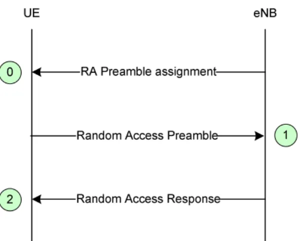
10.1.5.2 Non-contention based random access procedure ... 54
10.1.5.3 Interaction model between L1 and L2/3 for Random Access Procedure ... 54
10.1.7 Radio Access Network Sharing ... 56
10.1.8 Handling of Roaming and Area Restrictions for UEs in ECM-CONNECTED ... 56
10.2 Inter RAT ... 57
10.2.1 Cell reselection ... 57
10.2.2 Handover ... 57
10.2.2a Inter-RAT cell change order to GERAN with NACC ... 58
10.2.2b Inter-RAT handovers from E-UTRAN ... 58
10.2.2b.1 Data forwarding ... 58
10.2.2b.1.1 For RLC-AM bearers ... 58
10.2.2b.1.2 For RLC-UM bearers ... 59
10.2.3 Measurements ... 59
10.2.3.1 Inter-RAT handovers from E-UTRAN ... 59
10.2.3.2 Inter-RAT handovers to E-UTRAN ... 59
10.2.3.3 Inter-RAT cell reselection from E-UTRAN ... 59
10.2.3.4 Limiting measurement load at UE ... 59
10.2.4 Network Aspects ... 60
10.3 Mobility between E-UTRAN and Non-3GPP radio technologies ... 60
10.3.1 UE Capability Configuration ... 60
10.3.2 Mobility between E-UTRAN and cdma2000 network ... 60
10.3.2.1 Tunnelling of cdma2000 Messages over E-UTRAN between UE and cdma2000 Access Nodes ... 60
10.3.2.2 Mobility between E-UTRAN and HRPD ... 61
10.3.2.2.1 Mobility from E-UTRAN to HRPD ... 61
10.3.2.2.1.1 HRPD System Information Transmission in E-UTRAN ... 61
10.3.2.2.1.2 Measuring HRPD from E-UTRAN ... 61
10.3.2.2.1.2.1 Idle Mode Measurement Control ... 62
10.3.2.2.1.2.2 Active Mode Measurement Control ... 62
10.3.2.2.1.2.3 Active Mode Measurement ... 62
10.3.2.2.1.3 Pre-registration to HRPD Procedure ... 62
10.3.2.2.1.4 E-UTRAN to HRPD Cell Re-selection ... 62
10.3.2.2.1.5 E-UTRAN to HRPD Handover... 62
10.3.2.2.2 Mobility from HRPD to E-UTRAN ... 63
10.3.2.3 Mobility between E-UTRAN and cdma2000 1xRTT ... 63
10.3.2.3.1 Mobility from E-UTRAN to cdma2000 1xRTT ... 63
10.3.2.3.1.1 cdma2000 1xRTT System Information Transmission in E-UTRAN ... 63
10.3.2.3.1.2 Measuring cdma2000 1xRTT from E-UTRAN ... 63
10.3.2.3.1.2.1 Idle Mode Measurement Control ... 63
10.3.2.3.1.2.2 Active Mode Measurement Control ... 63
10.3.2.3.1.2.3 Active Mode Measurement ... 64
10.3.2.3.1.3 E-UTRAN to cdma2000 1xRTT Cell Re-selection ... 64
10.3.2.3.1.4 E-UTRAN to cdma2000 1xRTT Handover ... 64
10.3.2.3.2 Mobility from cdma2000 1xRTT to E-UTRAN ... 64
10.3.2.3.3 1xRTT CS Fallback ... 64
10.4 Area Restrictions ... 65
10.5 Mobility to and from CSG cells ... 65
10.5.0 Principles for idle-mode mobility with CSG cells ... 65
10.5.0.1 Intra-frequency mobility ... 65
10.5.0.2 Inter-frequency mobility ... 65
10.5.0.3 Inter-RAT Mobility ... 65
10.5.1 Inbound mobility to CSG cells ... 65
10.5.1.1 RRC_IDLE... 65
10.5.1.2 RRC_CONNECTED... 66
10.5.2 Outbound mobility from CSG cells ... 66
10.5.2.1 RRC_IDLE... 66
10.5.2.2 RRC_CONNECTED... 66
10.6 Measurement Model ... 66
11
Scheduling and Rate Control ... 67
11.1 Basic Scheduler Operation ... 67
11.1.1 Downlink Scheduling ... 67
11.1.2 Uplink Scheduling ... 67
11.2 Void ... 68
11.4 Rate Control of GBR and UE-AMBR ... 68
11.4.1 Downlink ... 68
11.4.2 Uplink ... 68
11.5 CQI reporting for Scheduling ... 69
12
DRX in RRC_CONNECTED ... 69
13 QoS
... 70
13.1 Bearer service architecture ... 71
13.2 QoS parameters ... 71
14 Security... 72
14.1 Overview and Principles ... 72
14.2 Security termination points... 74
14.3 State Transitions and Mobility ... 74
14.3.1 RRC_IDLE to RRC_CONNECTED ... 74
14.3.2 RRC_CONNECTED to RRC_IDLE ... 74
14.3.3 Intra E-UTRAN Mobility ... 75
14.4 AS Key Change in RRC_CONNECTED ... 75
14.5 Security Interworking ... 75
15 Void
... 75
16
Radio Resource Management aspects ... 75
16.1 RRM functions ... 76
16.1.1 Radio Bearer Control (RBC) ... 76
16.1.2 Radio Admission Control (RAC) ... 76
16.1.3 Connection Mobility Control (CMC) ... 76
16.1.4 Dynamic Resource Allocation (DRA) - Packet Scheduling (PS) ... 76
16.1.5 Inter-cell Interference Coordination (ICIC) ... 76
16.1.6 Load Balancing (LB) ... 77
16.1.7 Inter-RAT Radio Resource Management ... 77
16.1.8 Subscriber Profile ID for RAT/Frequency Priority ... 77
16.2 RRM architecture ... 77
16.2.1 Centralised Handling of certain RRM Functions ... 77
16.2.2 De-Centralised RRM ... 77
16.2.2.1 UE History Information ... 77
16.2.3 Load balancing control ... 78
17 RF
aspects
... 78
17.1 Spectrum deployments ... 7818 UE
capabilities ... 78
19 S1
Interface
... 79
19.1 S1 User plane ... 79 19.2 S1 Control Plane ... 79 19.2.1 S1 Interface Functions ... 80 19.2.1.1 S1 Paging function ... 8119.2.1.2 S1 UE Context Management function... 81
19.2.1.3 Initial Context Setup Function ... 81
19.2.1.3a UE Context Modification Function ... 81
19.2.1.4 Mobility Functions for UEs in ECM-CONNECTED ... 81
19.2.1.4.1 Intra-LTE Handover ... 81
19.2.1.4.2 Inter-3GPP-RAT Handover ... 81
19.2.1.5 E-RAB Service Management function ... 81
19.2.1.6 NAS Signalling Transport function ... 81
19.2.1.7 NAS Node Selection Function (NNSF) ... 82
19.2.1.8 S1-interface management functions ... 82
19.2.1.9 MME Load balancing Function ... 82
19.2.1.10 Location Reporting Function ... 82
19.2.1.11 Warning Message Transmission function ... 82
19.2.1.12 Overload Function ... 82
19.2.1.13 RAN Information Management Function ... 82
19.2.1.15 Configuration Transfer Function ... 83
19.2.2 S1 Interface Signalling Procedures ... 83
19.2.2.1 Paging procedure ... 84
19.2.2.2 S1 UE Context Release procedure ... 84
19.2.2.2.1 S1 UE Context Release (EPC triggered) ... 85
19.2.2.2.2 S1 UE Context Release Request (eNB triggered)... 85
19.2.2.3 Initial Context Setup procedure ... 85
19.2.2.3a UE Context Modification procedure ... 86
19.2.2.4 E-RAB signalling procedures... 87
19.2.2.4.1 E-RAB Setup procedure ... 87
19.2.2.4.2 E-RAB Modification procedure ... 88
19.2.2.4.3 E-RAB Release procedure ... 89
19.2.2.4.4 E-RAB Release Indication procedure ... 89
19.2.2.5 Handover signalling procedures ... 90
19.2.2.5.1 Handover Preparation procedure ... 90
19.2.2.5.2 Handover Resource Allocation procedure ... 90
19.2.2.5.3 Handover Notification procedure ... 91
19.2.2.5.4 Handover Cancellation ... 91
19.2.2.5.5 Path Switch procedure ... 92
19.2.2.5.6 Message sequence diagrams ... 92
19.2.2.5.7 eNB Status Transfer procedure ... 99
19.2.2.5.8 MME Status Transfer procedure ... 100
19.2.2.6 NAS transport procedures ... 100
19.2.2.7 S1 interface Management procedures ... 102
19.2.2.7.1 Reset procedure ... 102
19.2.2.7.1a eNB initiated Reset procedure ... 102
19.2.2.7.1b MME initiated Reset procedure ... 102
19.2.2.7.2 Error Indication functions and procedures... 103
19.2.2.7.2a eNB initiated error indication ... 103
19.2.2.7.2b MME initiated error indication ... 103
19.2.2.8 S1 Setup procedure ... 104
19.2.2.9 eNB Configuration Update procedure ... 104
19.2.2.9a eNB Configuration Transfer procedure ... 105
19.2.2.10 MME Configuration Update procedure ... 105
19.2.2.10a MME Configuration Transfer procedure ... 106
19.2.2.11 Location Reporting procedures ... 106
19.2.2.11.1 Location Reporting Control procedure ... 107
19.2.2.11.2 Location Report procedure ... 107
19.2.2.11.3 Location Report Failure Indication procedure ... 107
19.2.2.12 Overload procedure ... 108
19.2.2.12.1 Overload Start procedure ... 108
19.2.2.12.2 Overload Stop procedure ... 108
19.2.2.13 Write-Replace Warning procedure ... 108
19.2.2.14 eNB Direct Information Transfer procedure ... 109
19.2.2.15 MME Direct Information Transfer procedure ... 109
19.2.2.16 S1 CDMA2000 Tunnelling procedures ... 110
19.2.2.16.1 Downlink S1 CDMA2000 Tunnelling procedure ... 110
19.2.2.16.2 Uplink S1 CDMA2000 Tunnelling procedure... 110
20 X2
Interface ... 111
20.1 User Plane ... 111
20.2 Control Plane ... 111
20.2.1 X2-CP Functions ... 112
20.2.2 X2-CP Procedures ... 112
20.2.2.1 Handover Preparation procedure ... 113
20.2.2.2 Handover Cancel procedure ... 114
20.2.2.3 UE Context Release procedure ... 114
20.2.2.4 SN Status Transfer procedure ... 115
20.2.2.5 Error Indication procedure ... 115
20.2.2.6 Load Indication procedure ... 115
20.2.2.7 X2 Setup procedure ... 116
20.2.2.9 Reset procedure ... 117
20.2.2.10 Resource Status Reporting Initiation procedure ... 117
20.2.2.11 Resource Status Reporting procedure ... 117
20.2.3 Void ... 118
21
System and Terminal complexity ... 118
21.1 Overall System complexity ... 118
21.2 Physical layer complexity ... 118
21.3 UE complexity ... 118
22
Support for self-configuration and self-optimisation ... 118
22.1 Definitions ... 118
22.2 UE Support for self-configuration and self-optimisation ... 119
22.3 Self-configuration ... 120
22.3.1 Dynamic configuration of the S1-MME interface ... 120
22.3.1.1 Prerequisites ... 120
22.3.1.2 SCTP initialization ... 120
22.3.1.3 Application layer initialization ... 120
22.3.2 Dynamic Configuration of the X2 interface ... 120
22.3.2.1 Prerequisites ... 120
22.3.2.2 SCTP initialization ... 120
22.3.2.3 Application layer initialization ... 120
22.3.2a Automatic Neighbour Relation Function ... 121
22.3.3 Intra-LTE/frequency Automatic Neighbour Relation Function ... 122
22.3.4 Inter-RAT/Inter-frequency Automatic Neighbour Relation Function ... 123
22.3.5 Framework for PCI Selection ... 124
22.3.6 TNL address discovery ... 124
22.3.6.1 TNL address discovery of candidate eNB via S1 interface ... 124
23 Others
... 125
23.1 Support for real time IMS services ... 125
23.2 Subscriber and equipment trace ... 125
23.2.1 Signalling activation ... 125
23.2.2 Management activation ... 125
23.3 E-UTRAN Support for Warning Systems ... 125
23.3.1 Earthquake and Tsunami Warning System ... 125
Annex A (informative):
NAS Overview ... 126
A.1 Services and Functions ... 126
A.2 NAS protocol states & state transitions ... 126
Annex B (informative):
MAC and RRC Control ... 127
B.1 Difference
between
MAC and RRC control ... 127
B.2
Classification of MAC and RRC control functions ... 127
Annex C (informative):
System Information ... 128
C.1 SI
classification
... 128
C.1.1 Information valid across multiple cells ... 128
C.1.2 Information needed at cell/PLMN search ... 128
C.1.3 Information needed prior to cell camping ... 129
C.1.4 Information needed prior to cell access ... 129
C.1.5 Information needed while camping on a cell ... 130
C.1.6 Thoughts about category division... 131
C.2
Division of SI between static and flexible parts ... 131
C.2.1 Static part... 131
C.2.2 Flexible part... 132
C.2.3 Information whose location is FFS ... 133
C.2.4 Dedicated part ... 133
Annex E (informative):
Drivers for Mobility Control ... 135
E.1 Drivers ... 135
E.1.1 Best radio condition ... 136
E.1.2 Camp load balancing ... 136
E.1.3 Traffic load balancing ... 136
E.1.4 UE capability ... 136
E.1.5 Hierarchical cell structures ... 136
E.1.6 Network sharing ... 137
E.1.7 Private networks/home cells ... 137
E.1.8 Subscription based mobility control ... 137
E.1.9 Service based mobility control... 137
E.1.10 MBMS ... 137
E.2 Limitations for mobility control ... 137
E.2.1 UE battery saving ... 137
E.2.2 Network signalling/processing load ... 138
E.2.3 U-plane interruption and data loss ... 138
E.2.4 OAM complexity ... 138
E.3 Inter-frequency/RAT drivers ... 138
E.3.1 Mobility control during IDLE mode ... 138
E.3.2 Mobility control upon IDLE to ACTIVE transition ... 139
E.3.3 Mobility control during ACTIVE mode ... 140
E.3.4 Mobility control upon ACTIVE to IDLE transition ... 140
Annex F (informative):
Mobility and Access Control Requirements associated with Closed
Subscriber Group (CSG) Cells ... 142
F.1 Access Control ... 142
F.2 Mobility ... 142
F.3 Mobility performance guidelines ... 144
Annex G (informative):
Guideline for E-UTRAN UE capabilities ... 145
Annex H (informative):
PDCCH, PHICH and PUCCH Performance ... 147
Annex I (informative):
Change history ... 148
Foreword
This Technical Specification has been produced by the 3rd Generation Partnership Project (3GPP).
The contents of the present document are subject to continuing work within the TSG and may change following formal TSG approval. Should the TSG modify the contents of the present document, it will be re-released by the TSG with an identifying change of release date and an increase in version number as follows:
Version x.y.z where:
x the first digit:
1 presented to TSG for information; 2 presented to TSG for approval;
3 or greater indicates TSG approved document under change control.
y the second digit is incremented for all changes of substance, i.e. technical enhancements, corrections, updates, etc.
1 Scope
The present document provides an overview and overall description of the E-UTRAN radio interface protocol architecture. Details of the radio interface protocols are specified in companion specifications of the 36 series.
2 References
The following documents contain provisions which, through reference in this text, constitute provisions of the present document.
• References are either specific (identified by date of publication, edition number, version number, etc.) or non-specific.
• For a specific reference, subsequent revisions do not apply.
• For a non-specific reference, the latest version applies. In the case of a reference to a 3GPP document (including a GSM document), a non-specific reference implicitly refers to the latest version of that document in the same Release as the present document.
[1] 3GPP TR 21.905: "Vocabulary for 3GPP Specifications"
[2] 3GPP TR 25.913: "Requirements for Evolved UTRA (E-UTRA) and Evolved UTRAN (E-UTRAN)" [3] 3GPP TS 36.201: "Evolved Universal Terrestrial Radio Access (E-UTRA); Physical layer; General
description".
[4] 3GPP TS 36.211:"Evolved Universal Terrestrial Radio Access (E-UTRA); Physical Channels and Modulation "
[5] 3GPP TS 36.212: "Evolved Universal Terrestrial Radio Access (E-UTRA); Multiplexing and channel coding"
[6] 3GPP TS 36.213: "Evolved Universal Terrestrial Radio Access (E-UTRA); Physical layer procedures" [7] 3GPP TS 36.214: "Evolved Universal Terrestrial Radio Access (E-UTRA); Physical layer; Measurements" [8] IETF RFC 4960 (09/2007): "Stream Control Transmission Protocol"
[9] 3GPP TS 36.302: "Evolved Universal Terrestrial Radio Access (E-UTRA); Services provided by the physical layer"
[11] 3GPP TS 36.304: "Evolved Universal Terrestrial Radio Access (E-UTRA); User Equipment (UE) procedures in idle mode"
[12] 3GPP TS 36.306: "Evolved Universal Terrestrial Radio Access (E-UTRA); User Equipment (UE) radio access capabilities"
[13] 3GPP TS 36.321: "Evolved Universal Terrestrial Radio Access (E-UTRA); Medium Acces Control (MAC) protocol specification"
[14] 3GPP TS 36.322: "Evolved Universal Terrestrial Radio Access (E-UTRA); Radio Link Control (RLC) protocol specification"
[15] 3GPP TS 36.323: "Evolved Universal Terrestrial Radio Access (E-UTRA); Packet Data Convergence Protocol (PDCP) specification"
[16] 3GPP TS 36.331: "Evolved Universal Terrestrial Radio Access (E-UTRA); Radio Resource Control (RRC) protocol specification".
[17] 3GPP TS 23.401: "Technical Specification Group Services and System Aspects; GPRS enhancements for E-UTRAN access".
[18] 3GPP TR 24.801: "3GPP System Architecture Evolution (SAE); CT WG1 aspects".
[19] 3GPP TS 23.402: "3GPP System Architecture Evolution: Architecture Enhancements for non-3GPP accesses".
[20] 3GPP TR 24.301: "Non-Access-Stratum (NAS) protocol for Evolved Packet System (EPS); Stage 3". [21] 3GPP TS 36.133: "Evolved Universal Terrestrial Radio Access (E-UTRA); "Requirements for support of
radio resource management".
[22] 3GPP TS 33.401: "3GPP System Architecture Evolution: Security Architecture". [23] 3GPP TS 23.272: "Circuit Switched Fallback in Evolved Packet System; Stage 2". [24] 3GPP TS 33.401: "3GPP System Architecture Evolution: Security Architecture".
[25] 3GPP TS 36.413: "Evolved Universal Terrestrial Radio Access Network (E-UTRAN); S1 Application Protocol (S1AP)".
[26] 3GPP TS 23.003: "Numbering, addressing and identification". [27] 3GPP TR 25.922: "Radio Resource Management Strategies".
[28] 3GPP TS 23.216: "Single Radio voice Call continuity (SRVCC); Stage 2".
[29] 3GPP TS 32.421: "Subscriber and equipment trace: Trace concepts and requirements".
[30] 3GPP TS 32.422: "Subscriber and equipment trace; Trace control and configuration management". [31] 3GPP TS 32.423: "Subscriber and equipment trace: Trace data definition and management". [32] 3GPP TS 22.168: "Earthquake and Tsunami Warning System (ETWS) requirements; Stage 1".
3
Definitions, symbols and abbreviations
3.1 Definitions
For the purposes of the present document, the following terms and definitions apply. Carrier frequency: center frequency of the cell.
E-RAB: An E-RAB uniquely identifies the concatenation of an S1 Bearer and the corresponding Data Radio Bearer. When an E-RAB exists, there is a one-to-one mapping between this E-RAB and an EPS bearer of the Non Access Stratum as defined in [17].
Frequency layer: set of cells with the same carrier frequency.
Handover: procedure that changes the serving cell of a UE in RRC_CONNECTED.
3.2 Abbreviations
For the purposes of the present document, the abbreviations given in TR 21.905 [1] and the following apply. An abbreviation defined in the present document takes precedence over the definition of the same abbreviation, if any, in TR 21.905 [1].
ACK Acknowledgement ACLR Adjacent Channel Leakage Ratio
AM Acknowledge Mode
AMBR Aggregate Maximum Bit Rate ANR Automatic Neighbour Relation ARQ Automatic Repeat Request
BCCH Broadcast Control Channel
BCH Broadcast Channel
BSR Buffer Status Reports
C/I Carrier-to-Interference Power Ratio CAZAC Constant Amplitude Zero Auto-Correlation CBC Cell Broadcast Center
CMC Connection Mobility Control
CP Cyclic Prefix
C-plane Control Plane
C-RNTI Cell RNTI
CQI Channel Quality Indicator CRC Cyclic Redundancy Check CSG Closed Subscriber Group DCCH Dedicated Control Channel DL Downlink
DFTS DFT Spread OFDM
DRB Data Radio Bearer
DRX Discontinuous Reception
DTCH Dedicated Traffic Channel
DTX Discontinuous Transmission
DwPTS Downlink Pilot Time Slot ECGI E-UTRAN Cell Global Identifier
ECM EPS Connection Management
EMM EPS Mobility Management
eNB E-UTRAN NodeB
EPC Evolved Packet Core
EPS Evolved Packet System
E-RAB E-UTRAN Radio Access Bearer
ETWS Earthquake and Tsunami Warning System
E-UTRA Evolved UTRA
E-UTRAN Evolved UTRAN
FDD Frequency Division Duplex FDM Frequency Division Multiplexing GERAN GSM EDGE Radio Access Network GNSS Global Navigation Satellite System GSM Global System for Mobile communication GBR Guaranteed Bit Rate
GP Guard Period
HARQ Hybrid ARQ
HO Handover HRPD High Rate Packet Data
HSDPA High Speed Downlink Packet Access
ICIC Inter-Cell Interference Coordination
IP Internet Protocol
LB Load Balancing
LCR Low Chip Rate
LTE Long Term Evolution
MAC Medium Access Control
MBR Maximum Bit Rate
MCE Multi-cell/multicast Coordination Entity
MCH Multicast Channel
MCS Modulation and Coding Scheme MIB Master Information Block MIMO Multiple Input Multiple Output MME Mobility Management Entity MSAP MCH Subframe Allocation Pattern
NACK Negative Acknowledgement
NAS Non-Access Stratum
NCC Next Hop Chaining Counter
NH Next Hop key
NNSF NAS Node Selection Function NR Neighbour cell Relation
NRT Neighbour Relation Table
OFDM Orthogonal Frequency Division Multiplexing OFDMA Orthogonal Frequency Division Multiple Access
P-GW PDN Gateway
P-RNTI Paging RNTI
PA Power Amplifier
PAPR Peak-to-Average Power Ratio PBCH Physical Broadcast CHannel PBR Prioritised Bit Rate
PCCH Paging Control Channel
PCFICH Physical Control Format Indicator CHannel
PCH Paging Channel
PCI Physical Cell Identifier
PDCCH Physical Downlink Control CHannel PDSCH Physical Downlink Shared CHannel PDCP Packet Data Convergence Protocol
PDU Protocol Data Unit
PHICH Physical Hybrid ARQ Indicator CHannel
PHY Physical layer
PLMN Public Land Mobile Network PMCH Physical Multicast CHannel PRACH Physical Random Access CHannel
PRB Physical Resource Block
PSC Packet Scheduling
PUCCH Physical Uplink Control CHannel PUSCH Physical Uplink Shared CHannel
QAM Quadrature Amplitude Modulation
QCI QoS Class Identifier QoS Quality of Service RA-RNTI Random Access RNTI
RAC Radio Admission Control
RACH Random Access Channel RAT Radio Access Technology
RB Radio Bearer
RBC Radio Bearer Control
RBG Radio Bearer Group
RF Radio Frequency
RIM RAN Information Management
RLC Radio Link Control
RNC Radio Network Controller
RNL Radio Network Layer
RNTI Radio Network Temporary Identifier ROHC Robust Header Compression RRC Radio Resource Control RRM Radio Resource Management
RU Resource Unit
S-GW Serving Gateway
S1-MME S1 for the control plane
SI System Information
SIB System Information Block SI-RNTI System Information RNTI S1-U S1 for the user plane
SAE System Architecture Evolution
SAP Service Access Point
SC-FDMA Single Carrier – Frequency Division Multiple Access
SCH Synchronization Channel
SDF Service Data Flow
SDMA Spatial Division Multiple Access
SDU Service Data Unit
SeGW Security Gateway
SFN System Frame Number
SR Scheduling Request SRB Signalling Radio Bearer
SU Scheduling Unit
TA Tracking Area
TB Transport Block
TCP Transmission Control Protocol
TDD Time Division Duplex TFT Traffic Flow Template
TM Transparent Mode
TNL Transport Network Layer
TTI Transmission Time Interval
UE User Equipment
UL Uplink
UM Un-acknowledge Mode
UMTS Universal Mobile Telecommunication System
U-plane User plane
UTRA Universal Terrestrial Radio Access
UTRAN Universal Terrestrial Radio Access Network UpPTS Uplink Pilot Time Slot
VRB Virtual Resource Block
X2-C X2-Control plane
X2-U X2-User plane
4 Overall
architecture
The E-UTRAN consists of eNBs, providing the E-UTRA user plane (PDCP/RLC/MAC/PHY) and control plane (RRC) protocol terminations towards the UE. The eNBs are interconnected with each other by means of the X2 interface. The eNBs are also connected by means of the S1 interface to the EPC (Evolved Packet Core), more specifically to the MME (Mobility Management Entity) by means of the S1-MME and to the Serving Gateway (S-GW) by means of the S1-U. The S1 interface supports a many-to-many relation between MMEs / Serving Gateways and eNBs.
The E-UTRAN architecture is illustrated in Figure 4 below.
S
1 S1
S1 S1
X2 X2
Figure 4-1: Overall Architecture
4.1 Functional
Split
- Functions for Radio Resource Management: Radio Bearer Control, Radio Admission Control, Connection Mobility Control, Dynamic allocation of resources to UEs in both uplink and downlink (scheduling); - IP header compression and encryption of user data stream;
- Selection of an MME at UE attachment when no routing to an MME can be determined from the information provided by the UE;
- Routing of User Plane data towards Serving Gateway;
- Scheduling and transmission of paging messages (originated from the MME);
- Scheduling and transmission of broadcast information (originated from the MME or O&M); - Measurement and measurement reporting configuration for mobility and scheduling; - Scheduling and transmission of ETWS messages (originated from the MME). The MME hosts the following functions (see 3GPP TS 23.401 [17]):
- NAS signalling;
- NAS signalling security; - AS Security control;
- Inter CN node signalling for mobility between 3GPP access networks;
- Idle mode UE Reachability (including control and execution of paging retransmission); - Tracking Area list management (for UE in idle and active mode);
- PDN GW and Serving GW selection;
- MME selection for handovers with MME change;
- SGSN selection for handovers to 2G or 3G 3GPP access networks; - Roaming;
- Authentication;
- Bearer management functions including dedicated bearer establishment; - Support for ETWS message transmission.
The Serving Gateway (S-GW) hosts the following functions (see 3GPP TS 23.401 [17]): - The local Mobility Anchor point for inter-eNB handover;
- Mobility anchoring for inter-3GPP mobility;
- E-UTRAN idle mode downlink packet buffering and initiation of network triggered service request procedure; - Lawful Interception;
- Packet routeing and forwarding;
- Transport level packet marking in the uplink and the downlink; - Accounting on user and QCI granularity for inter-operator charging; - UL and DL charging per UE, PDN, and QCI.
The PDN Gateway (P-GW) hosts the following functions (see 3GPP TS 23.401 [17]): - Per-user based packet filtering (by e.g. deep packet inspection);
- UE IP address allocation;
- Transport level packet marking in the downlink;
- UL and DL service level charging, gating and rate enforcement; - DL rate enforcement based on APN-AMBR;
This is summarized on the figure below where yellow boxes depict the logical nodes, white boxes depict the functional entities of the control plane and blue boxes depict the radio protocol layers.
NOTE: it is assumed that no other logical E-UTRAN node than the eNB is needed for RRM purposes. Moreover, due to the different usage of inter-cell RRM functionalities, each inter-cell RRM functionality should be considered separately in order to assess whether it should be handled in a centralised manner or in a distributed manner.
NOTE: MBMS related functions in E-UTRAN are described separately in subclause 15.
Figure 4.1-1: Functional Split between E-UTRAN and EPC
4.2 Interfaces
4.2.1 S1
Interface
4.2.2 X2
Interface
4.3
Radio Protocol architecture
4.3.1 User
plane
The figure below shows the protocol stack for the user-plane, where PDCP, RLC and MAC sublayers (terminated in eNB on the network side) perform the functions listed for the user plane in subclause 6, e.g. header compression, ciphering, scheduling, ARQ and HARQ;
Figure 4.3.1-1: User-plane protocol stack
4.3.2 Control
plane
The figure below shows the protocol stack for the control-plane, where:
- PDCP sublayer (terminated in eNB on the network side) performs the functions listed for the control plane in subclause 6, e.g. ciphering and integrity protection;
- RLC and MAC sublayers (terminated in eNB on the network side) perform the same functions as for the user plane;
- RRC (terminated in eNB on the network side) performs the functions listed in subclause 7, e.g.: - Broadcast;
- Paging;
- RRC connection management; - RB control;
- Mobility functions;
- UE measurement reporting and control.
- NAS control protocol (terminated in MME on the network side) performs among other things: - EPS bearer management;
- Authentication;
- ECM-IDLE mobility handling; - Paging origination in ECM-IDLE; - Security control.
Figure 4.3.2-1: Control-plane protocol stack
4.4 Synchronization
Diverse methods and techniques are preferred depending on synchronization requirements. As no single method can cover all E-UTRAN applications a logical port at eNB may be used for reception of timing and/or frequency and/or phase inputs pending to the synchronization method chosen.
4.5 IP
fragmentation
Fragmentation function in IP layer on S1 and X2 shall be supported.
Configuration of S1-U (X2-U) link MTU in the eNB/ S-GW according to the MTU of the network domain the node belongs to shall be considered as a choice at network deployment. The network may employ various methods to handle IP fragmentation, but the specific methods to use are implementation dependant.
At the establishment/modification of an EPS bearer, the network may signal a value that is to be used as MTU by the UE IP stack (it is FFS how the requirement on the UE should be formulated). It is also FFS if the MTU is signalled by the MME or the eNB.
4.6 Support
of
HeNBs
4.6.1 Architecture
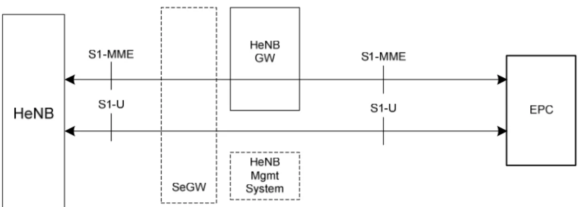
Figure 4.6.1-1 shows a logical architecture for the HeNB that has a set of S1 interfaces to connect the HeNB to the EPC. The configuration and authentication entities as shown here should be common to HeNBs and HNBs.
The E-UTRAN architecture may deploy a Home eNB Gateway (HeNB GW) to allow the S1 interface between the HeNB and the EPC to scale to support a large number of HeNBs. The HeNB GW serves as a concentrator for the C-Plane, specifically the S1-MME interface. The S1-U interface from the HeNB may be terminated at the HeNB GW, or a direct logical U-Plane connection between HeNB and S-GW may be used (as shown in Figure 4.6.1-1).
This version of the specification does not support X2 connectivity of HeNBs. The S1 interface is defined as the interface:
- Between the HeNB GW and the Core Network, - Between the HeNB and the HeNB GW, - Between the HeNB and the Core Network, - Between the eNB and the Core Network.
The HeNB GW appears to the MME as an eNB. The HeNB GW appears to the HeNB as an MME. The S1 interface between the HeNB and the EPC is the same whether the HeNB is connected to the EPC via a HeNB GW or not. The HeNB GW shall connect to the EPC in a way that inbound and outbound mobility to cells served by the HeNB GW shall not necessarily require inter MME handovers. One HeNB serves only one cell.
The functions supported by the HeNB shall be the same as those supported by an eNB (with the possible exception of NNSF) and the procedures run between a HeNB and the EPC shall be the same as those between an eNB and the EPC.
eNB
MME / S-GW
MME / S-GW
eNB
eNB
X2 X2 X2E-UTRAN
HeNB
HeNB
HeNB GW
S1 S1 S1HeNB
S1Figure 4.6.1-2: Overall E-UTRAN Architecture with deployed HeNB GW.
4.6.2 Functional
Split
The HeNB hosts the same functions as an eNB as described in section 4.1, with the following additional specifications in case of connection to the HeNB GW:
- Discovery of a suitable Serving HeNB GW
- A HeNB shall only connect to a single HeNB GW at one time, namely no S1 Flex function shall be used at the HeNB in case of connection to the HeNB GW.
- If the HeNB is connected to a HeNB GW, it will not simultaneously connect to another HeNB GW, or another MME.
- The TAC and PLMN ID used by the HeNB shall also be supported by the HeNB GW.
- When the HeNB connects to a HeNB GW, selection of an MME at UE attachment is hosted by the HeNB GW instead of the HeNB;
- HeNBs may be deployed without network planning. A HeNB may be moved from one geographical area to another and therefore it may need to connect to different HeNB GWs depending on its location.
The HeNB GW hosts the following functions:
- Relaying UE-associated S1 application part messages between the MME serving the UE and the HeNB serving the UE;
- Terminating non-UE associated S1 application part procedures towards the HeNB and towards the MME. Note that when a HeNB GW is deployed, non-UE associated procedures shall be run between HeNBs and the HeNB GW and between the HeNB GW and the MME.
- Optionally terminating S1-U interface with the HeNB and with the S-GW. - Supporting TAC and PLMN ID used by the HeNB.
- X2 interfaces shall not be established between the HeNB GW and other nodes.
- Optionally performing paging optimisation in case the Allowed CSG List of the paged UE is included in the PAGING message.
In addition to functions specified in section 4.1, the MME hosts the following functions: - Access control for UEs that are members of Closed Subscriber Groups (CSG). - Optionally performing paging optimisation.
NOTE: The MME or HeNB GW should not include the Allowed CSG List when sending the paging message directly to an untrusted HeNB or eNB.
4.6.3 Interfaces
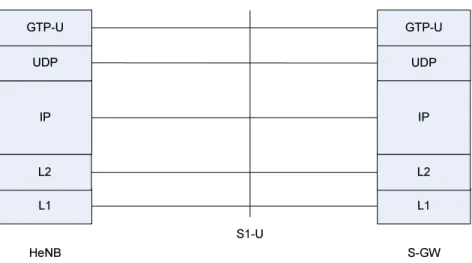
4.6.3.1
Protocol Stack for S1 User Plane
The S1-U data plane is defined between the HeNB, HeNB GW and the S-GW. The figures below shows the S1-U protocol stack with and without the HeNB GW.
S1-U
L1
UDP
GTP-U
S-GW
L1
IP
UDP
HeNB
GTP-U
L2
IP
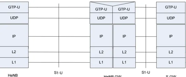
L2
Figure 4.6.3.1-2: User plane for S1-U interface for HeNB with HeNB GW
The HeNB GW may optionally terminate the user plane towards the HeNB and towards the S-GW, and provide a relay function for relaying User Plane data between the HeNB and the S-GW.
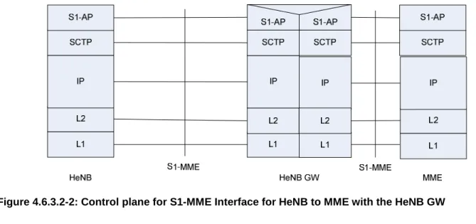
4.6.3.2
Protocol Stacks for S1 Control Plane
The two figures below show the S1-MME protocol stacks with and without the HeNB GW.
When the HeNB GW is not present (Fig. 4.6.3.2-1), all the S1 procedures are terminated at the HeNB and the MME. When present (Fig. 4.6.3.2-2), the HeNB GW shall terminate the non-UE-dedicated procedures – both with the HeNB, and with the MME. The HeNB GW shall provide a relay function for relaying Control Plane data between the HeNB and the MME. The scope of any protocol function associated to a non-UE-dedicated procedure shall be between HeNB and HeNB GW and/or between HeNB GW and MME.
Any protocol function associated to an UE-dedicated-procedure shall reside within the HeNB and the MME only.
Access Layer
SCTP
S1-AP
L1
L2
IP
SCTP
HeNB
MME
S1-AP
S1-MME
L2
IP
Figure 4.6.3.2-2: Control plane for S1-MME Interface for HeNB to MME with the HeNB GW
5
Physical Layer for E-UTRA
Downlink and uplink transmissions are organized into radio frames with 10 ms duration. Two radio frame structures are supported:
- Type 1, applicable to FDD, - Type 2, applicable to TDD.
Frame structure Type 1 is illustrated in Figure 5.1-1. Each 10 ms radio frame is divided into ten equally sized sub-frames. Each sub-frame consists of two equally sized slots. For FDD, 10 subframes are available for downlink transmission and 10 subframes are available for uplink transmissions in each 10 ms interval. Uplink and downlink transmissions are separated in the frequency domain.
Figure 5.1-1: Frame structure type 1
Frame structure Type 2 is illustrated in Figure 5.1-2. Each 10 ms radio frame consists of two half-frames of 5 ms each. Each half-frame consists of eight slots of length 0.5 ms and three special fields: DwPTS, GP and UpPTS. The length of DwPTS and UpPTS is configurable subject to the total length of DwPTS, GP and UpPTS being equal to 1ms. Both 5ms and 10ms switch-point periodicity are supported. Subframe 1 in all configurations and subframe 6 in configuration with 5ms switch-point periodicity consist of DwPTS, GP and UpPTS. Subframe 6 in configuration with 10ms switch-point periodicity consists of DwPTS only. All other subframes consist of two equally sized slots.
For TDD, GP is reserved for downlink to uplink transition. Other Subframes/Fields are assigned for either downlink or uplink transmission. Uplink and downlink transmissions are separated in the time domain.
Figure 5.1-2: Frame structure type 2 (for 5ms switch-point periodicity) Table 5.1-1: Uplink-downlink allocations.
Configuration Switch-point periodicity Subframe number
0 1 2 3 4 5 6 7 8 9 0 5 ms D S U U U D S U U U 1 5 ms D S U U D D S U U D 2 5 ms D S U D D D S U D D 3 10 ms D S U U U D D D D D 4 10 ms D S U U D D D D D D 5 10 ms D S U D D D D D D D 6 5 ms D S U U U D S U U D
The physical channels of E-UTRA are: Physical broadcast channel (PBCH)
- The coded BCH transport block is mapped to four subframes within a 40 ms interval; - 40 ms timing is blindly detected, i.e. there is no explicit signalling indicating 40 ms timing;
- Each subframe is assumed to be self-decodable, i.e. the BCH can be decoded from a single reception, assuming sufficiently good channel conditions.
Physical control format indicator channel (PCFICH)
- Informs the UE about the number of OFDM symbols used for the PDCCHs; - Transmitted in every downlink or special subframe.
Physical downlink control channel (PDCCH)
- Informs the UE about the resource allocation of PCH and DL-SCH, and Hybrid ARQ information related to DL-SCH;
- Carries the uplink scheduling grant.
Physical Hybrid ARQ Indicator Channel (PHICH)
- Carries Hybrid ARQ ACK/NAKs in response to uplink transmissions. Physical downlink shared channel (PDSCH)
- Carries the DL-SCH and PCH. Physical multicast channel (PMCH)
Physical uplink control channel (PUCCH)
- Carries Hybrid ARQ ACK/NAKs in response to downlink transmission; - Carries Scheduling Request (SR);
- Carries CQI reports.
Physical uplink shared channel (PUSCH) - Carries the UL-SCH.
Physical random access channel (PRACH) - Carries the random access preamble.
5.1
Downlink Transmission Scheme
5.1.1 Basic
transmission scheme based on OFDM
The downlink transmission scheme is based on conventional OFDM using a cyclic prefix. The OFDM sub-carrier spacing is Δf = 15 kHz. 12 consecutive sub-carriers during one slot correspond to one downlink resource block. In the frequency domain, the number of resource blocks, NRB, can range from NRB-min = 6 to NRB-max = 110.
In addition there is also a reduced sub-carrier spacingΔflow = 7.5 kHz, only for MBMS-dedicated cell.
In the case of 15 kHz sub-carrier spacing there are two cyclic-prefix lengths, corresponding to seven and six OFDM symbols per slot respectively.
- Normal cyclic prefix: TCP = 160×Ts (OFDM symbol #0) , TCP = 144×Ts (OFDM symbol #1 to #6)
- Extended cyclic prefix: TCP-e = 512×Ts (OFDM symbol #0 to OFDM symbol #5)
where Ts = 1/ (2048 ×Δf)
In case of 7.5 kHz sub-carrier spacing, there is only a single cyclic prefix length TCP-low = 1024×Ts, corresponding to 3
OFDM symbols per slot.
In case of FDD, operation with half duplex from UE point of view is supported.
5.1.2
Physical-layer
processing
The downlink physical-layer processing of transport channels consists of the following steps: - CRC insertion: 24 bit CRC is the baseline for PDSCH;
- Channel coding: Turbo coding based on QPP inner interleaving with trellis termination; - Physical-layer hybrid-ARQ processing;
- Channel interleaving;
- Scrambling: transport-channel specific scrambling on DL-SCH, BCH, and PCH. Common MCH scrambling for all cells involved in a specific MBSFN transmission;
- Modulation: QPSK, 16QAM, and 64QAM; - Layer mapping and pre-coding;
5.1.3
Physical downlink control channel
The downlink control signalling (PDCCH) is located in the first n OFDM symbols where n ≤ 4 and consists of: - Transport format and resource allocation related to DL-SCH and PCH, and hybrid ARQ information related to
DL-SCH;
- Transport format, resource allocation, and hybrid-ARQ information related to UL-SCH; Transmission of control signalling from these groups is mutually independent.
Multiple physical downlink control channels are supported and a UE monitors a set of control channels.
Control channels are formed by aggregation of control channel elements, each control channel element consisting of a set of resource elements. Different code rates for the control channels are realized by aggregating different numbers of control channel elements.
QPSK modulation is used for all control channels. Each separate control channel has its own set of x-RNTI.
There is an implicit relation between the uplink resources used for dynamically scheduled data transmission, or the DL control channel used for assignment, and the downlink ACK/NAK resource used for feedback
5.1.4
Downlink Reference signal
The downlink reference signals consist of known reference symbols inserted in the first and third last OFDM symbol of each slot. There is one reference signal transmitted per downlink antenna port. The number of downlink antenna ports equals 1, 2, or 4. The two-dimensional reference signal sequence is generated as the symbol-by-symbol product of a dimensional orthogonal sequence and a dimensional pseudo-random sequence. There are 3 different two-dimensional orthogonal sequences and 170 different two-two-dimensional pseudo-random sequences. Each cell identity corresponds to a unique combination of one orthogonal sequence and one pseudo-random sequence, thus allowing for 504 unique cell identities 168 cell identity groups with 3 cell identities in each group).
Frequency hopping can be applied to the downlink reference signals. The frequency hopping pattern has a period of one frame (10 ms). Each frequency hopping pattern corresponds to one cell identity group.
The downlink MBSFN reference signals consist of known reference symbols inserted every other sub-carrier in the 3rd, 7th and 11th OFDM symbol of sub-frame in case of 15kHz sub-carrier spacing and extended cyclic prefix
5.1.5
Downlink multi-antenna transmission
Multi-antenna transmission with 2 and 4 transmit antennas is supported. The maximum number of codeword is two irrespective to the number of antennas with fixed mapping between code words to layers.
Spatial division multiplexing (SDM) of multiple modulation symbol streams to a single UE using the same time-frequency (-code) resource, also referred to as Single-User MIMO (SU-MIMO) is supported. When a MIMO channel is solely assigned to a single UE, it is known as SU-MIMO. Spatial division multiplexing of modulation symbol streams to different UEs using the same time-frequency resource, also referred to as MU-MIMO, is also supported. There is semi-static switching between SU-MIMO and MU-MIMO per UE.
In addition, the following techniques are supported:
- Code-book-based pre-coding with a single pre-coding feedback per full system bandwidth when the system bandwidth (or subset of resource blocks) is smaller or equal to12RB and per 5 adjacent resource blocks or the full system bandwidth (or subset of resource blocks) when the system bandwidth is larger than 12RB.
5.1.6 MBSFN
transmission
MBSFN is supported for the MCH transport channel. Multiplexing of transport channels using MBSFN and non-MBSFN transmission is done on a per-sub-frame basis. Additional reference symbols, transmitted using non-MBSFN are transmitted within MBSFN subframes.
5.1.7
Physical layer procedure
5.1.7.1 Link
adaptation
Link adaptation (AMC: adaptive modulation and coding) with various modulation schemes and channel coding rates is applied to the shared data channel. The same coding and modulation is applied to all groups of resource blocks belonging to the same L2 PDU scheduled to one user within one TTI and within a single stream.
5.1.7.2 Power
Control
Downlink power control can be used.5.1.7.3 Cell
search
Cell search is the procedure by which a UE acquires time and frequency synchronization with a cell and detects the Cell ID of that cell. E-UTRA cell search supports a scalable overall transmission bandwidth corresponding to 72 sub-carriers and upwards.
E-UTRA cell search is based on following signals transmitted in the downlink: the primary and secondary synchronization signals, the downlink reference signals.
The primary and secondary synchronization signals are transmitted over the centre 72 sub-carriers in the first and sixth subframe of each frame.
Neighbour-cell search is based on the same downlink signals as initial cell search.
5.1.8
Physical layer measurements definition
The physical layer measurements to support mobility are classified as:- within E-UTRAN (intra-frequency, inter-frequency); - between E-UTRAN and GERAN/UTRAN (inter-RAT);
- between E-UTRAN and non-3GPP RAT (Inter 3GPP access system mobility).
For measurements within E-UTRAN at least two basic UE measurement quantities shall be supported: - Reference symbol received power (RSRP);
- E-UTRA carrier received signal strength indicator (RSSI).
5.2
Uplink Transmission Scheme
5.2.1
Basic transmission scheme
For both FDD and TDD, the uplink transmission scheme is based on single-carrier FDMA, more specifically DFTS-OFDM.
Figure 5.2.1-1: Transmitter scheme of SC-FDMA
The uplink sub-carrier spacing Δf = 15 kHz. The sub-carriers are grouped into sets of 12 consecutive sub-carriers, corresponding to the uplink resource blocks. 12 consecutive sub-carriers during one slot correspond to one uplink resource block. In the frequency domain, the number of resource blocks, NRB, can range from NRB-min = 6 to NRB-max =
110.
There are two cyclic-prefix lengths defined: Normal cyclic prefix and extended cyclic prefix corresponding to seven and six SC-FDMA symbol per slot respectively.
- Normal cyclic prefix: TCP = 160×Ts (SC-FDMA symbol #0) , TCP = 144×Ts (SC-FDMA symbol #1 to #6)
- Extended cyclic prefix: TCP-e = 512×Ts (SC-FDMA symbol #0 to SC-FDMA symbol #5)
5.2.2 Physical-layer
processing
The uplink physical layer processing of transport channels consists of the following steps: - CRC insertion: 24 bit CRC is the baseline for PUSCH;
- Channel coding: turbo coding based on QPP inner interleaving with trellis termination; - Physical-layer hybrid-ARQ processing;
- Scrambling: UE-specific scrambling;
- Modulation: QPSK, 16QAM, and 64QAM (64 QAM optional in UE); - Mapping to assigned resources and antennas ports.
5.2.3
Physical uplink control channel
The PUCCH shall be mapped to a control channel resource in the uplink. A control channel resource is defined by a code and two resource blocks, consecutive in time, with hopping at the slot boundary.
Depending on presence or absence of uplink timing synchronization, the uplink physical control signalling can differ. In the case of time synchronization being present, the outband control signalling consists of:
- CQI; - ACK/NAK;
- Scheduling Request (SR).
The CQI informs the scheduler about the current channel conditions as seen by the UE. If MIMO transmission is used, the CQI includes necessary MIMO-related feedback.
The HARQ feedback in response to downlink data transmission consists of a single ACK/NAK bit per HARQ process. PUCCH resources for SR and CQI reporting are assigned and can be revoked through RRC signalling. An SR is not necessarily assigned to UEs acquiring synchronization through the RACH (i.e. synchronised UEs may or may not have a dedicated SR channel). PUCCH resources for SR and CQI are lost when the UE is no longer synchronized.
5.2.4
Uplink Reference signal
Uplink reference signals [for channel estimation for coherent demodulation] are transmitted in the 4-th block of the slot [assumed normal CP]. The uplink reference signals sequence length equals the size (number of sub-carriers) of the assigned resource.
The uplink reference signals are based on prime-length Zadoff-chu sequences that are cyclically extended to the desired length.
Multiple reference signals can be created:
- Based on different Zadoff-Chu sequence from the same set of Zadoff-Chu sequences; - Different shifts of the same sequence.
5.2.5 Random
access preamble
The physical layer random access burst consists of a cyclic prefix, a preamble, and a guard time during which nothing is transmitted.
The random access preambles are generated from Zadoff-Chu sequences with zero correlation zone, ZC-ZCZ, generated from one or several root Zadoff-Chu sequences.
5.2.6
Uplink multi-antenna transmission
The baseline antenna configuration for uplink MIMO is MU-MIMO. To allow for MU-MIMO reception at the Node B, allocation of the same time and frequency resource to several UEs, each of which transmitting on a single antenna, is supported.
Closed loop type adaptive antenna selection transmit diversity shall be supported for FDD (optional in UE).
5.2.7 Physical
channel
procedure
5.2.7.1 Link
adaptation
Uplink link adaptation is used in order to guarantee the required minimum transmission performance of each UE such as the user data rate, packet error rate, and latency, while maximizing the system throughput.
Three types of link adaptation are performed according to the channel conditions, the UE capability such as the maximum transmission power and maximum transmission bandwidth etc., and the required QoS such as the data rate, latency, and packet error rate etc. Three link adaptation methods are as follows.
- Adaptive transmission bandwidth; - Transmission power control;
- Adaptive modulation and channel coding rate.
5.2.7.2
Uplink Power control
Intra-cell power control: the power spectral density of the uplink transmissions can be influenced by the eNB.
5.2.7.3
Uplink timing control
The timing advance is derived from the UL received timing and sent by the eNB to the UE which the UE uses to advance/delay its timings of transmissions to the eNB so as to compensate for propagation delay and thus time align the transmissions from different UEs with the receiver window of the eNB.
5.3 Transport
Channels
The physical layer offers information transfer services to MAC and higher layers. The physical layer transport services are described by how and with what characteristics data are transferred over the radio interface. An adequate term for this is 'Transport Channel'.
NOTE: This should be clearly separated from the classification of what is transported, which relates to the concept of logical channels at MAC sublayer.
Downlink transport channel types are:
1. Broadcast Channel (BCH) characterised by: - fixed, pre-defined transport format;
- requirement to be broadcast in the entire coverage area of the cell. 2. Downlink Shared Channel (DL-SCH) characterised by:
- support for HARQ;
- support for dynamic link adaptation by varying the modulation, coding and transmit power; - possibility to be broadcast in the entire cell;
- possibility to use beamforming;
- support for both dynamic and semi-static resource allocation;
- support for UE discontinuous reception (DRX) to enable UE power saving. NOTE: the possibility to use slow power control depends on the physical layer. 3. Paging Channel (PCH) characterised by:
- support for UE discontinuous reception (DRX) to enable UE power saving (DRX cycle is indicated by the network to the UE);
- requirement to be broadcast in the entire coverage area of the cell;
- mapped to physical resources which can be used dynamically also for traffic/other control channels. 4. Multicast Channel (MCH) characterised by:
- requirement to be broadcast in the entire coverage area of the cell; - support for MBSFN combining of MBMS transmission on multiple cells;
- support for semi-static resource allocation e.g. with a time frame of a long cyclic prefix. Uplink transport channel types are:
1. Uplink Shared Channel (UL-SCH) characterised by:
- possibility to use beamforming; (likely no impact on specifications)
- support for dynamic link adaptation by varying the transmit power and potentially modulation and coding; - support for HARQ;
- support for both dynamic and semi-static resource allocation.
NOTE: the possibility to use uplink synchronisation and timing advance depend on the physical layer. 2. Random Access Channel(s) (RACH) characterised by:
- collision risk;
NOTE: the possibility to use open loop power control depends on the physical layer solution.
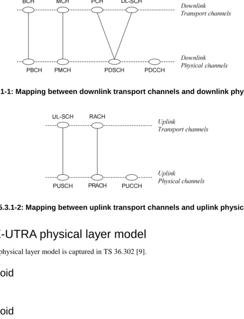
5.3.1
Mapping between transport channels and physical channels
The figures below depict the mapping between transport and physical channels:Figure 5.3.1-1: Mapping between downlink transport channels and downlink physical channels
Figure 5.3.1-2: Mapping between uplink transport channels and uplink physical channels
5.4
E-UTRA physical layer model
The E-UTRAN physical layer model is captured in TS 36.302 [9].
5.4.1 Void
5.4.2 Void
6 Layer
2
Layer 2 is split into the following sublayers: Medium Access Control (MAC), Radio Link Control (RLC) and Packet Data Convergence Protocol (PDCP).
This subclause gives a high level description of the Layer 2 sub-layers in terms of services and functions. The two figures below depict the PDCP/RLC/MAC architecture for downlink and uplink, where:
- Service Access Points (SAP) for peer-to-peer communication are marked with circles at the interface between sublayers. The SAP between the physical layer and the MAC sublayer provides the transport channels. The SAPs between the MAC sublayer and the RLC sublayer provide the logical channels.
- The multiplexing of several logical channels (i.e. radio bearers) on the same transport channel (i.e. transport block) is performed by the MAC sublayer;
- In both uplink and downlink, only one transport block is generated per TTI in the non-MIMO case.
Segm.
ARQ etc
Multiplexing UE
1Segm.
ARQ etc
...
HARQ
Multiplexing UE
nHARQ
BCCH PCCH
Scheduling / Priority Handling
Logical Channels
Transport Channels
MAC
RLC
ARQ etc
Segm.
ARQ etc
Segm.
PDCP
ROHC
ROHC
ROHC
ROHC
Radio Bearers
Security
Security
Security
Security
...
CCCH
Figure 6-1: Layer 2 Structure for DL
NOTE: The eNB may not be able to guarantee that a L2 buffer overflow will never occur. If such overflow occurs, UE may discard packets in the L2 buffer.
6.1 MAC
Sublayer
This subclause provides an overview on services and functions provided by the MAC sublayer.
6.1.1
Services and Functions
The main services and functions of the MAC sublayer include: - Mapping between logical channels and transport channels;
- Multiplexing/demultiplexing of MAC SDUs belonging to one or different logical channels into/from transport blocks (TB) delivered to/from the physical layer on transport channels;
- scheduling information reporting; - Error correction through HARQ;
- Priority handling between logical channels of one UE;
- Priority handling between UEs by means of dynamic scheduling; - Transport format selection;
- Padding.
6.1.2 Logical
Channels
Different kinds of data transfer services as offered by MAC. Each logical channel type is defined by what type of information is transferred.
A general classification of logical channels is into two groups:
- Control Channels (for the transfer of control plane information); - Traffic Channels (for the transfer of user plane information).
There is one MAC entity per cell. MAC generally consists of several function blocks (transmission scheduling functions, per UE functions, MAC control functions, transport block generation…). Transparent Mode is only applied to BCCH and PCCH.
6.1.2.1 Control
Channels
Control channels are used for transfer of control plane information only. The control channels offered by MAC are: - Broadcast Control Channel (BCCH)
A downlink channel for broadcasting system control information. - Paging Control Channel (PCCH)
A downlink channel that transfers paging information and system information change notifications. This channel is used for paging when the network does not know the location cell of the UE.
- Common Control Channel (CCCH)
Channel for transmitting control information between UEs and network. This channel is used for UEs having no RRC connection with the network.
A point-to-point bi-directional channel that transmits dedicated control information between a UE and the network. Used by UEs having an RRC connection.
6.1.2.2 Traffic
Channels
Traffic channels are used for the transfer of user plane information only. The traffic channels offered by MAC are: - Dedicated Traffic Channel (DTCH)
A Dedicated Traffic Channel (DTCH) is a point-to-point channel, dedicated to one UE, for the transfer of user information. A DTCH can exist in both uplink and downlink.
6.1.3
Mapping between logical channels and transport channels
6.1.3.1
Mapping in Uplink
The figure below depicts the mapping between uplink logical channels and uplink transport channels:
CCCH DCCH DTCH UL-SCH RACH Uplink Logical channels Uplink Transport channels
Figure 6.1.3.1-1: Mapping between uplink logical channels and uplink transport channels
In Uplink, the following connections between logical channels and transport channels exist: - CCCH can be mapped to UL-SCH;
- DCCH can be mapped to UL- SCH; - DTCH can be mapped to UL-SCH.
6.1.3.2
Mapping in Downlink
The figure below depicts the mapping between downlink logical channels and downlink transport channels:
Figure 6.1.3.2-1: Mapping between downlink logical channels and downlink transport channels
- BCCH can be mapped to BCH; - BCCH can be mapped to DL-SCH; - PCCH can be mapped to PCH; - CCCH can be mapped to DL-SCH; - DCCH can be mapped to DL-SCH; - DTCH can be mapped to DL-SCH.
6.2 RLC
Sublayer
This subclause provides an overview on services, functions and PDU structure provided by the RLC sublayer. Note that:
- The reliability of RLC is configurable: some radio bearers may tolerate rare losses (e.g. TCP traffic); - Radio Bearers are not characterized by a fixed sized data unit (e.g. a fixed sized RLC PDU).
6.2.1
Services and Functions
The main services and functions of the RLC sublayer include: - Transfer of upper layer PDUs;
- Error Correction through ARQ (only for AM data transfer);
- Concatenation, segmentation and reassembly of RLC SDUs (only for UM and AM data transfer); - Re-segmentation of RLC data PDUs (only for AM data transfer);
- In sequence delivery of upper layer PDUs (only for UM and AM data transfer); - Duplicate detection (only for UM and AM data transfer);
- Protocol error detection and recovery;
- RLC SDU discard (only for UM and AM data transfer); - RLC re-establishment.
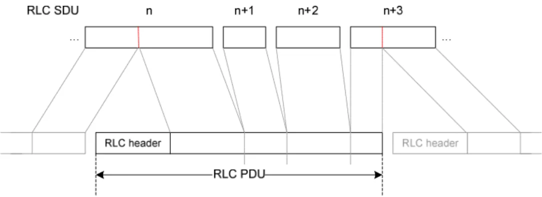
6.2.2 PDU
Structure
Figure 6.2.2-1 below depicts the RLC PDU structure where:
- The PDU sequence number carried by the RLC header is independent of the SDU sequence number (i.e. PDCP sequence number);
- A red dotted line indicates the occurrence of segmentation;
- Because segmentation only occurs when needed and concatenation is done in sequence, the content of an RLC PDU can generally be described by the following relations:
- {0; 1} last segment of SDUi + [0; n] complete SDUs + {0; 1} first segment of SDUi+n+1 ; or
Figure 6.2.2-1: RLC PDU Structure
6.3 PDCP
Sublayer
This subclause provides an overview on services, functions and PDU structure provided by the PDCP sublayer.
6.3.1
Services and Functions
The main services and functions of the PDCP sublayer for the user plane include: - Header compression and decompression: ROHC only;
- Transfer of user data;
- In-sequence delivery of upper layer PDUs at PDCP re-establishment procedure for RLC AM; - Duplicate detection of lower layer SDUs at PDCP re-establishment procedure for RLC AM; - Retransmission of PDCP SDUs at handover for RLC AM;
- Ciphering and deciphering;
- Timer-based SDU discard in uplink.
NOTE: When compared to UTRAN, the lossless DL RLC PDU size change is not required. The main services and functions of the PDCP for the control plane include:
- Ciphering and Integrity Protection; - Transfer of control plane data.
6.3.2 PDU
Structure
Figure 6.3.2-1 below depicts the PDCP PDU structure for user plane data, where: - PDCP PDU and PDCP header are octet-aligned;
- PDCP header can be either 1 or 2 bytes long.
The structures for control PDCP PDUs and for control plane PDCP data PDUs are specified in [15].
6.4 Void
7 RRC
This subclause provides an overview on services and functions provided by the RRC sublayer.
7.1
Services and Functions
The main services and functions of the RRC sublayer include:
- Broadcast of System Information related to the non-access stratum (NAS); - Broadcast of System Information related to the access stratum (AS); - Paging;
- Establishment, maintenance and release of an RRC connection between the UE and E-UTRAN including: - Allocation of temporary identifiers between UE and E-UTRAN;
- Configuration of signalling radio bearer(s) for RRC connection: - Low priority SRB and high priority SRB.
- Security functions including key management;
- Establishment, configuration, maintenance and release of point to point Radio Bearers; - Mobility functions including:
- UE measurement reporting and control of the reporting for inter-cell and inter-RAT mobility; - Handover;
- UE cell selection and reselection and control of cell selection and reselection; - Context transfer at handover.
- QoS management functions;
- UE measurement reporting and control of the reporting; - NAS direct message transfer to/from NAS from/to UE.
7.2