Multicast for Small Conferences
Torsten Braun
IAM-00-008
Multicast for Small Conferences
Torsten Braun
Institute of Computer Science and Applied Mathematics, University of Berne, Switzerland http://www.iam.unibe.ch/~braun
Abstract
This report describes a concept to support scalable multicast communications for small conferencing groups in the Inter-net. The concept called Multicast for Small Conferences (MSC) has in particular been designed for supporting telephone/ audio conferences over the Internet. An important goal is smooth deployment in the Internet. The concept has been signifi-cantly been influenced by the Small Group Multicast (SGM) concept and IP Version 6 (IPv6).
CR Categories and Subject Decriptors:
C.2.1 Network Architecture and Design, C.2.2 Network Protocols, C.2.5 Local and Wide-Area Networks, C.2.6 Internet-working
General Terms Algorithms, Design Keywords
IP Multicast, Audio Conferencing, IP Version 6
I. Introduction
Future IP networks will serve as backbone for telephone networks. Telecommunication companies are currently begin-ning to replace telephone backbone connections by IP networks. The natural IP technology for audio/telephone conferences is IP multicast. However, IP multicast does not scale for many small groups which are common in telephone conference sce-narios [1]. This paper presents a solution to that problem based on extensions of IPv6 and of the session description protocol (SDP) which is used for describing real-time sessions in the Internet.
Section II gives an overview of related work to achieve scalable multicast communication in the Internet. Section III describes the main application scenario of our solution for scalable multicast called Multicast for Small Conferences (MSC). MSC that has been designed for an easy and smooth deployment in IPv6 networks is described in Section IV. Finally, Section V describes the modifications that are required on application level in order to make use of MSC.
II. Scalable Multicast Techniques
IP Multicast suffers from a significant scalability problem since multicast routing entries within routers can not be aggre-gated such as unicast routing entries. While leading unicast address prefixes can be used for routing entry aggregation, multi-cast address selection can be arbitrary so that multimulti-cast addresses with equal similar prefixes do not need to have any relation to each other such as common multicast delivery trees. The Multicast Address Allocation Architecture (Malloc) addresses this problem in the context of allocation mechanims for unique multicast addresses [9].
The scalability problem gets even worse since multicast routing entries do not only consist of the destination multicast address but may even include a source address. This means that a backbone router needs a multicast routing entry for each global multicast address (or each source / multicast address pair) even if this multicast group consists of a few members only. Several proposals have arised recently addressing this scalability problem.
The Small Group Multicast (SGM) [1] concept proposes to introduce a new protocol layer between IP and the transport layer. The corresponding SGM header has been specified as a new protocol header following the IPv4 header [2] and consists of a list of the IP addresses of all group members. When sending a multicast packet, the unicast addresses of all receivers are put into the IP destination address and the SGM header respectively. A SGM router scans the complete address list of an arrived packet and determines the outgoing interfaces for each of the addresses. A new packet copy is generated for each out-going interface. Each address list of a packet then only contains the addresses that can be reached via that interface. While SGM solves the scalability problem, several problems remain:
• SGM introduces a new protocol and a new protocol id in the IP header.
• For a smooth deployment, SGM tunnels have to be set up among SGM capable routers.
• SGM does not rely on established multicast mechanisms such as IGMP making it difficult to allow native multicast receivers to join a multicast group. Although gateways that translate IP multicast packets into SGM packets can be deployed, the problem remains that those gateway have to synchronize themselves in order make sure that the same IP multicast address is being used for the same set of receivers or multicast group respectively.
However, the SGM authors claim that there is no need for IP multicast (class D) addresses. The avoidance of class D IPv4 addresses has many benefits such as avoidance of multicast address allocation [9] and control over receivers by the sender.
Nevertheless, there are existing IP multicast applications which should also be supported. A similar approach as SGM called Somecast is based on IPv4 options [7].
Like the proposal described in this paper, the Multiple Destination Option on IPv6 (MDO6) is based on SGM and IPv6. MDO6 also proposes to define a new IPv6 routing header or a new destination option. MDO6 is based on the SGM concept and, therefore, does not support native IPv6 multicast. MDO6 proposes to support an ordered list of receivers in the new extension headers in order to make router processing more efficient [10]. MDO6 proposes new ICMP messages for exploring multicast delivery trees.
Another approach called Dynamic Tunnel Multicast (DTM) [14], avoids the scalability problem by establishing unicast tunnels among multicast routers, similar to tunnels used in the MBone. However, in the case of DTM, dynamic tunnels are established requiring a special protocol to discover potential tunnel endpoints and to establish / terminate the tunnels. In addi-tion, multicast routing states in branching nodes are required, i.e. in nodes where a multicast packet must be forwarded via more than one outgoing interface. The approach also requires that some multicast routing protocol is being used for exchang-ing multicast routexchang-ing information.
Finally, the REUNITE mechanism has been proposed [13] to address the scalability problem. REUNITE does not use IP multicast addresses but unicast addresses only. Multicast groups are identified by the root‘s unicast address and a port num-ber. When a multicast group consists of a single receiver only, the sender sends the multicast packet to that receiver‘s unicast address. The root also multicasts tree messages periodically down the multicast tree, which consists of a single branch ini-tially. If another receiver joins the group, it sends a join message towards the root. If this join message meets a router of the tree, that router suppresses join message forwarding and includes the receiver into the tree. Subsequent messages down the tree that are identified by the root‘s source address and port are then also forwarded towards the new receiver. In that case, the router replaces the destination address by the new receiver‘s destination address. Again, native IP multicast mechanisms are not used and new protocol messages have to be introduced.
III. Telephone Conferencing over the Internet
The Internet more and more replaces traditional telecommunication networks. Telecommunication companies are already beginning to interconnect telephone exchanges via the Internet instead of using PDH or SDH connections. The use of Internet technology in the backbone yields additional advantages for audio conferencing. Traditional audio conferencing in telephone networks is quite complex to set up and is very inefficient regarding bandwidth usage since audio traffic is always sent to the MCU that finally distributes it via point-to-point connections to the various receivers. Therefore, it seems to be very promis-ing to use IP multicast for the Internet interconnection of gateways that provide access to legacy telephone users or even of Internet telephony terminals directly. To support a conference, the IP terminals and the gateways serving the conferencing participants have to join a common multicast group and may exchange the traffic via IP multicast mechanisms. This avoids the multiple transport of the same traffic over the backbone network as it is the case in traditional telephone conferences based on MCUs. The gateways should also support non-multicast capable IP terminals or phones.
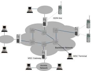
Figure 1 shows our target scenario. Gateways are interconnected via the Internet and communicate using a multicast mechanism. The gateways serve non-multicast capable end systems such as unicast IP phones or legacy phones. In such a scenario, typically a relatively small number of participants are involved. Therefore, the multicast group consisting of both IP multicast receivers (IP telephony terminals) and gateways is relatively small, may be less than 10 group members. For such a small multicast group, it makes hardly sense to burden backbone Internet routers and force them to store a multicast routing entry for this group or even for each (source, multicast address) pair. In particular the SGM concept seems to be very useful for supporting the target scenario, but the disadvantages mentioned above have to be overcome.
Figure 1: Multicast Conferencing Scenario
MSC Gateway Access Network Backbone Network ISDN line MSC Terminal
To support such a scenario described above and depicted in Figure 1, we propose to use the MSC multicast mechanism for interconnecting the gateways and IP terminals. The gateways and IP terminals must then be MSC capable. We, therefore, call these MSC gateways and MSC terminals, hereafter. The MSC gateways have then also the task to serve non-MSC capa-ble IP terminals such as IPv4 only terminals or IPv6 terminals that do not support MSC. While for IPv4 terminals IPv6/IPv4 packet translation has to be performed, for IPv6 terminals only extension headers and options are inserted, modified or deleted by the MSC gateways.
IV. Multicast for Small Conferences
We propose to use the Multicast for Small Conferences (MSC) concept for multicast packet delivery in the Internet back-bone while current available intra-domain multicast routing mechanisms shall be used for regional or access networks. This approach avoids multicast routing overhead in backbone routers. Those have only to maintain unicast routing tables but should be able to process the MSC protocol information included as IPv6 extension headers or options.
A. IPv6 Extensions for MSC
In contrast to define a new protocol such as SGM we propose to realize the MSC concept based on IPv6, in particular on the IPv6 routing header. The IPv6 routing header (type 0) (Figure 2) has been proposed to be used for a kind of source routing [3]. However, multicast addresses must not appear in a routing header of type 0, or in the IPv6 destination address field of a packet carrying a routing header of type 0.
To overcome this limitation we propose two solutions. The first (short-term) solution is compatible with all current IPv6 routers, while the second solution is recommended for long-term usage. In both solutions the routing header carries a list of unicast addresses of all multicast group members, that means the MSC gateways and MSC terminals as shown in Figure 1. In addition, the multicast address is also carried in the IPv6 packet. While in the first solution the multicast address is carried in a newly defined IPv6 destination option, in the second solution it is carried at the end of the newly defined type 1 IPv6 rout-ing header.
+-+-+-+-+-+-+-+-+-+-+-+-+-+-+-+-+-+-+-+-+-+-+-+-+-+-+-+-+-+-+-+-+ | Next Header | Hdr Ext Len | Routing Type=0| Segments Left | +-+-+-+-+-+-+-+-+-+-+-+-+-+-+-+-+-+-+-+-+-+-+-+-+-+-+-+-+-+-+-+-+ | Reserved | +-+-+-+-+-+-+-+-+-+-+-+-+-+-+-+-+-+-+-+-+-+-+-+-+-+-+-+-+-+-+-+-+ | | + + | | + Address[1] + | | + + | | +-+-+-+-+-+-+-+-+-+-+-+-+-+-+-+-+-+-+-+-+-+-+-+-+-+-+-+-+-+-+-+-+ | | + + | | + Address[2] + | | + + | | +-+-+-+-+-+-+-+-+-+-+-+-+-+-+-+-+-+-+-+-+-+-+-+-+-+-+-+-+-+-+-+-+ . . . . . . . . . +-+-+-+-+-+-+-+-+-+-+-+-+-+-+-+-+-+-+-+-+-+-+-+-+-+-+-+-+-+-+-+-+ | | + + | | + Address[n] + | | + + | | +-+-+-+-+-+-+-+-+-+-+-+-+-+-+-+-+-+-+-+-+-+-+-+-+-+-+-+-+-+-+-+-+
Solution I
The destination options header is used to carry optional information that need be examined only by a packet's destination node(s). The destination options header is identified by a next header value of 60 in the preceding header, and has the format shown in Figure 3.
+-+-+-+-+-+-+-+-+-+-+-+-+-+-+-+-+-+-+-+-+-+-+-+-+-+-+-+-+-+-+-+-+ | Next Header | Hdr Ext Len | | +-+-+-+-+-+-+-+-+-+-+-+-+-+-+-+-+ + | | . . . Options . . . | | +-+-+-+-+-+-+-+-+-+-+-+-+-+-+-+-+-+-+-+-+-+-+-+-+-+-+-+-+-+-+-+-+
Figure 3: IPv6 Destination Options format
The options field (Figure 4) is of variable length, but must be an integer multiple of 8 octets long. It contains one or more TLV-encoded (TLV: type, length, value) options.
+++++++++++++++++ -| Option Type -| Opt Data Len -| Option Data +++++++++++++++++
-Figure 4: IPv6 Options
In our case, the option data should contain an IPv6 multicast address, so the option length is 16 bytes. The option type identifiers are internally encoded such that their highest-order two bits specify the action that must be taken if the processing IPv6 node does not recognize the option type. In our case these two bits should be set to 00 so that an IPv6 router just skips over this option and continues processing the header. The third-highest-order bit of the option type specifies whether or not the option data of that option can change en-route to the packet's final destination. When an authentication header is present in the packet, for any option whose data may change en-route, its entire Option Data field must be treated as zero-valued octets when computing or verifying the packet's authenticating value: the value of 1 should be set since the option might change en-route, in particular if the option is inserted or discarded.
Solution II
For the second (long-term) solution we propose to define a new routing header (type 1) which can very nicely serve for the implementation of the MSC concept. The syntax of this routing header is exactly the same as for the type 0 routing header but with type = 1. The difference to the first solution is that now the IPv6 multicast address is located at the end of the routing header address list, while in the first solution the multicast address in the destination option precedes the routing header.
In the following we call both the new destination option + the type 0 routing header and the newly defined type 1 routing header as the „MSC routing header“. However, we discuss the approach based on solution I, but it works for solution II in a near identical way.
B. MSC Routing Header Processing
A MSC routing header is generated by a sender that is either a MSC terminal or a MSC gateway as depicted in Figure 1. A sender creates an unicast address list of all group members and puts (if possible the nearest) one into the IPv6 destination address. All other member addresses are put into the MSC routing header, preferably ordered by the distance from the sender. The multicast address is put into the destination options header.
If the sender detects that members have to be reached via different outgoing interfaces or if branches occur after a few hops, a packet for each outgoing interface / branch is generated with the list of members that can be reached via that interface / branch. This means that a sender divides the address list into N parts and sends N copies of the packet to the N generated lists. Separating the address list into N parts should be done in such a way that nodes close to each other are put into the same sub list. The sender can determine such a node sub set by analyzing traceroutes, and by grouping together the addresses with longest common beginning sequence of intermediate routers. Of course, the benefit of multicast in terms of lower bandwidth usage might be decreased.
In any case, an IPv6 packet is forwarded from a sender to a MSC router that has to perform MSC routing header process-ing:
• An IPv6 router that does not understand the newly defined destination option forwards the packet towards the address specified in the IPv6 destination address.
• A MSC capable IPv6 router processes the address list and duplicates the packet for each outgoing interface that is used to reach an address of the list. The duplicated packets only contain the unicast addresses that can be reached via that
inter-• A receiving end system which finds it‘s address in the address list creates a packet for the higher protocol encapsulated in the IPv6 packet by copying the multicast address found in the new destination option into the IPv6 destination address and by removing the routing header. This packet is delivered to the higher protocol for further processing. A MSC gate-way forwards the packet to local multicast receivers using an appropriate scope.
If the routing header contained further unicast addresses, the receiver‘s address is removed from the address list, and a packet is generated with the address of the nearest node in the IPv6 destination address. This packet is forwarded via the outgoing interface of the end system. A multi-homed end system might also generate several copies of the packet if it can reach nodes of the address list via different interfaces / branches. In this case, the receiving end system behaves similar as the sender of the packet or a MSC capable router.
In general, the address list of the MSC routing header can be built based on two options: According to „normal“ IPv6 routing header rules, visited addresses are not discarded but the segments left counter is set to the number of address still to be visited (first option). The second option is to discard all addresses that are not further required for routing header process-ing. In the following we assume that the first approach is taken, but again there are no principal differences compared to the second one. The main advantage of the first option is that the IPv6 routing header is processed in the „traditional way“ while the second option achieves better efficiency due to the shorter routing header to be carried.
The MSC concept allows MSC functionality in receiving end systems only or in MSC routers (MSC gateways) only enabling smooth deployment. In the case that routers do not support MSC, but only end systems do, the packets are for-warded from one receiver to the other which might introduce significant delays. Of course, it depends on the type of applica-tions and the group size whether forwarding among end systems is applicable. With a tolerable audio delay of 150 ms and delays of 10 ms in national IP networks and 30 ms in continental IP networks, group sizes of 15 respectively 5 can be sup-ported. In the case, that only gateways support MSC, the packets are forwarded to these MSC gateways that have to distribute the packets via local IP multicast.
C. Case Study
Example
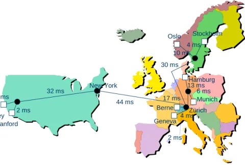
Let us assume a conference scenario between Berne, Geneva, Munich, Frankfurt, Stockholm, Oslo, Stanford, and Berke-ley. Figure 5 shows the connections between the different sites and the measured delays between the routers. The delays have been measured during day-time by round-trip-time (rtt) measurements using traceroute. We assume that one-way delay equals to rtt/2. In the following considerations we assume to send a packet from Berne to all other destinations. Please note, that further cases are possible, the discussed cases only cover some most probable ones.
Figure 5: Internet delays in an example conference scenario
Case I
All five routers depicted as black points (these are core routers at network exchange points) are MSC capable. This would allow to implement MSC without any additional overhead concerning bandwidth usage compared to „normal“ IP multicast. The maximum delay is the delay from Berne to Stanford, which is 80 ms. In this case, the Zürich router receives a packet from Berne and generates the following four packet copies: copy 1 is sent to Geneva, copy 2 to Munich and Hamburg, copy 3 to Oslo and Stockholm, and copy 4 to Berkeley and Stanford.
2 ms 4 ms 13 ms 44 ms 30 ms 17 ms 6 ms 10 ms 4 ms 32 ms 1 ms 2 ms Berkeley Stanford Stockholm Oslo Hamburg Munich Berne Geneva Zürich New York
Case II
Only one router per continent is MSC capable. This might be two routers in Zürich and in New York. In this case, the Zürich router distributes a packet within Europe and forwards a copy to New York. The New York router then sends two cop-ies to Stanford and Berkeley, while the Zürich router sends copcop-ies to all European participants. While the delay does not increase, the intra-continental bandwidth overhead increases significantly. However, only one packet will travel across the trans-atlantic link.
Case III
We have only one MSC capable router per country or region/domain and assume to have no MSC router in the core. In that case, a copy of a packet can be sent to each of these routers or to one after the other (e.g., from Berne -> Switzerland (2ms) -> Germany (2+17=19 ms) -> Scandinavia (19+47=66 ms) -> USA (66+74=140 ms)). Each MSC router then forwards the packet using IP multicast with an appropriate scope. In that case, multicast forwarding / routing is only performed within a region but not between regions/domains.
Case IV
No core router is MSC capable and only some access routers close to the end systems or the end systems themselves are MSC capable. In this case, we have to send a packet from one member to the next. First we begin with distributing the packet within Europe, i.e. Berne -> Geneva (6 ms) -> Munich (6+27 ms) -> Hamburg (6+27+19 ms) -> Stockholm (6+27+19+60 ms) -> Oslo (6+27+19+60+14 ms). The packet arrives after 126 ms at Oslo and would arrive after additional 40+44+32+1=117 ms, i.e after 243 ms at Stanford. Of course it is too late. However by generating two packets at Berne (one for Europe and one for the US), our limit of 150 ms would have been met. In this case, also the bandwidth overhead com-pared to IP multicast would have been very low. There would have been a single duplicate packet between Berne and Zürich only.
The decision to generate two packets and to put the right address list can be based on traceroute analysis. For example, the following hops can be found between a computer at Berne and three computers at Munich, Oslo, and Stanford:
traceroute to tum.www.ze.tu-muenchen.de 1 haydn66.unibe.ch 2 beethoven.unibe.ch 3 charon.unibe.ch 4 swiBE1-F1-0.switch.ch 5 swiZHX-A4-0-7.switch.ch 6 swiCE1-A4-0-0-6.switch.ch 7 switch.ch.ten-155.net 8 ch-de.de.ten-155.net 9 IR-Frankfurt1.win-ip.dfn.de 10 zr-frankfurt1.win-ip.dfn.de 11 zr-karlsruhe1.win-ip.dfn.de 12 zr-muenchen1.win-ip.dfn.de 13 lrz-muenchen2.win-ip.dfn.de 14 kr-lrz-muenchen1.lrz-muenchen.de 15 csrkbd.lrz-muenchen.de 16 tum.www.ze.tu-muenchen.de traceroute to ernst.uio.no 1 haydn66.unibe.ch 2 beethoven.unibe.ch 3 charon.unibe.ch 4 swiBE1-F1-0.switch.ch 5 swiZHX-A4-0-7.switch.ch 6 swiCE1-A4-0-0-6.switch.ch 7 switch.ch.ten-155.net 8 ch-se.se.ten-155.net 9 sw-gw.nordu.net 10 e-gw.nordu.net 11 no-gw2.nordu.net 12 osloS-gw.uninett.no 13 128.39.3.130 14 uio-gw7.uio.no 15 ernst.uio.no
traceroute to www.LB-A.stanford.edu 1 haydn66.unibe.ch 2 beethoven.unibe.ch 3 charon.unibe.ch 4 swiBE1-F1-0.switch.ch 5 swiZHX-A4-0-7.switch.ch 6 swiEG1-A6-0-0-1.switch.ch 8 212.1.200.149 9 Abilene-DANTE.abilene.ucaid.edu 10 clev-nycm.abilene.ucaid.edu 11 ipls-clev.abilene.ucaid.edu 12 kscy-ipls.abilene.ucaid.edu 13 dnvr-kscy.abilene.ucaid.edu 14 scrm-dnvr.abilene.ucaid.edu 15 198.32.249.61 16 STAN--SUNV.POS.calren2.net 17 i2-gateway.Stanford.EDU 18 Core3-gateway.Stanford.EDU 19 171.64.3.110 20 www3.Stanford.EDU
This example shows that the first seven hops are identical for the two European destinations, while only the first five hops are equal for US and European destinations. This means that very different transmissions paths are used for European and US destinations.
D. Comparison with SGM
Although MSC is based on ideas similar to SGM, there are significant differences among both approaches: • MSC is based on IPv6 avoiding to introduce a new protocol.
• MSC has also benefits in legacy IPv6 networks, i.e. there is no need to set up tunnels between any gateways such as pro-posed for SGM. However, introducing MSC in core routers significantly improves bandwidth efficiency and delay. • MSC uses unicast forwarding in the backbone only while multicast routing in local network environments can be further
used.
• MSC allows applications to use native IP multicast. Gateways need only to insert an MSC routing header instead of doing complete address mapping as in SGM. This allows to use exactly the same multicast address at different multicast sites without the need for synchronizing the address translations at the various gateways.
E. Problems
The IPv6 based MSC concept described above has several problems to be solved.
• The IPv6 routing header creates overhead that is increasing with the group size. This might be a problem for audio appli-cations where the packet sizes are usually relatively short. This problem might be severe in wireless networks. However, we believe that in future wired networks this problem should be neglible. The overhead problem can be solved by gate-ways serving as a MSC receiver and forwarding the received packets via native IPv6 multicast to the other receivers after discarding the routing header.
• MSC is an IPv6 only solution and requires the MSC routers and gateways to support IPv6 and to be connected to the 6Bone. Another question is how to support IPv4 only end systems. We propose to use MSC gateways for IPv6 / IPv4 packet translation in a similar way as phones are supported by these gateways. Since the current IPv6 address architecture proposes to use 232 IPv6 multicast addresses only [8] and to use the lower 32 bits of an IPv6 address for the group identi-fier with a fixed leading 96 bit prefix, a 1:1 mapping between IPv6 and IPv4 multicast addresses can be performed. • All senders need to know the IPv6 unicast addresses of the group members. This problem can be solved by a group
con-trol protocol by which the MSC receivers announce conference group membership to each other. This information might be distributed within session descriptions of the session announcement protocol (SAP) by which session descriptions according to SDP are distributed over a well-known multicast address. The integration of SDP and MSC is discussed in the next Section.
V. Integration of MSC into Audio Conferences
An audio/phone conference is often an event that is negotiated among the participants by means of electronic mail or other announcements. Based on these negotiations, the participants may then dial-in to a conference server and get access to the conference after being challenged for some authentication data. We call this a in conference hereafter. In such a call-in conference, session descriptions are pre-announced uscall-ing email, a HTML page or SAP [5]. SAP may be used to broadcast SDP [4] descriptions over such a dial-in conference with certain parameters required by the participants. A WWW page may
INVITE message might then be sent to the MCU which replies by a response containing a session description. For both email and WWW distribution, the use of the MIME content type "application/sdp" should be used.
Alternatively, conferences are set up spontaneously, e.g. if two people talking with each other decide to invite another per-son in order to join the conference. Therefore, such a conference scenario is called invited conference in the following. For the required signalling the Session Intitation Protocol (SIP) has been developed [6] within the IETF. In that case, further par-ticipants are explicitly invited to the conference. In that case, a caller invites a callee by a SIP INVITE message and announces the conference parameters within the SIP INVITE message using SDP.
In any of the above cases, a client desiring to join a conference or being invited to a conference gets a SDP description with parameters about the conference. One such parameter is the address to which audio packets have to be sent. This could be either one ore more unicast addresses or a multicast address if the conference is using IP multicast for data distribution. For this purpose the connection identifier of SDP should be used. However, the current SAP RFC only allows IPv4 identifi-ers, but IPv6 addresses have been proposed in [11]. A typical SDP description may look as follows:
v=0
o=tbraun 2890844526 2890842807 IN IP4 130.92.65.130 s=RA_Lecture
i=Lecture on computer architecture
u=http://www.iam.unibe.ch/~rvs/lectures/ra [email protected] (Torsten Braun) c=IN IP4 224.3.16.17
t=2873397496 2873404696 a=recvonly
m=audio 49170 RTP/AVP 0
In this case, the address information (IPv4 multicast address is given by the „c“ identifier. An IPv6 multicast address might be described by
c=IN IP6 FF02::E003:1011
In order to provide the MSC routing header support we propose to add the unicast addresses of the target receivers by attribute lines of the complete session
a=receivers: IN IP6 IPv6_1 IPv6_2 ... IPv6_n
with IPv6_j = the unicast IPv6 address of the different receivers.
In that case the SDP description of a conference must be kept up to date if distributed by SAP or SIP. In any case, a new participant has to register somewhere, e.g. at the owner or coordinator of the conference. The entity which is contacted for registration and which might decide to include the new participant into the conference and is in charge for updating the SDP descriptions.
A possible scenario might be that a conference participant registers at a web page or by sending an email for a conference. A registration script verifies the authorization to join the conference and adds the participant‘s IPv6 address (i.e. an address of either a MSC terminal or a MSC gateway) to the session‘s SDP description. SAP may be used for SDP announcements. In that case, all participants have permanently to listen to new SAP announcements and have to insert the new addressing infor-mation derived from SDP into their multicast packets.
The data are received by a MSC gateway directly from a phone (ISDN, GSM, analog) via an ISDN line or from a non-MSC aware IP client and have to be converted into IPv6 packets. The converting application then builds the non-MSC routing header and forwards the IPv6 packet. If the MSC gateway receives a native IPv6 multicast packet, it puts the IPv6 multicast address into the destination option and adds the type 0 routing header before forwarding the IPv6 packet.
VI. Conclusions
This paper described a concept for multicast support of small conference groups. This concept is based on ideas of SGM and on IPv6 and allows smooth introduction of the MSC concept. An initial analysis of an example scenario showed the fea-sibility of the concept in order to support small globally distributed conferencing groups. A scientific challenge is to develop algorithms for deciding which MSC options to use. This depends on many parameters such as network topology and delays, number of participants, capabilities of end systems, gateways and routers etc. Some of these parameters can be determined by using tools such as traceroute or by analyzing the sender/receiver reports of the RTP Control Protocol (RTCP, [12]) .
VII. Acknowledgments
The author thanks Linqing Liu and Rick Boivie for comments on this paper and for providing pointers to other related work.
VIII. References
[1] R. Boivie, N. Feldman, Ch. Metz: Small Group Multicast: A New Solution for Multicasting on the Internet, Internet Computing, Vol. 4, No. 3, May/June 2000
[2] R. Boivie, N. Feldman: Small Group Multicast, Internet Draft, work in progress, draft-boivie-sgm-01.txt, July 2000 [3] S. Deering, R. Hinden: Internet Protocol, Version 6 (IPv6) Specification, RFC 2460, December 1998
[4] M. Handley, V. Jacobson: SDP: Session Description Protocol, RFC 2327, April 1998
[5] M. Handley, C. Perkins, E. Whelan: Session Announcement Protocol, Internet Draft, work in progress, draft-ietf-mmusic-sap-v2-06.txt, March 2000
[6] M. Handley, H. Schulzrinne, E. Schooler, J. Rosenberg: SIP: Session Initiation Protocol, RFC 2543, March 1999 [7] D. Helder, S. Jamin: IPv4 Option for Somecast, Internet Draft, work in progress, draft-dhelder-somecast-00.txt, July
2000
[8] R. Hinden, S. Deering: IP Version 6 Addressing Architecture, RFC 2373, July 1998
[9] IETF Working Group Multicast-Address Allocation (malloc), http://www.ietf.org/html.charters/malloc-charter.html [10] Imai Yuji: Multiple Destination Option on IPv6 (MDO6), Internet Draft, work in progress, draft-imai-mdo6-01.txt,
March 2000
[11] B.Quinn: SDP Source-Filters, Internet Draft, work in progress, draft-ietf-mmusic-sdp-srcfilter-00.txt, May 2000 [12] H. Schulzrinne, S. Casner, R. Frederick, V. Jacobson: RTP: A Transport Protocol for Real-Time Applications, RFC
1889, January 1996
[13] I. Stoica, T. S. E. Ng, and H. Zhang: REUNITE: A Recursive Unicast Approach to Multicast, Proceedings of IEEE Infocom‘00, Tel-Aviv, March 2000
[14] J. Tian and G. Neufeld: Forwarding state reduction for sparse mode multicast communication, Proceedings of IEEE Infocom‘98, San Francisco, p. 711, March/April 1998