Enterprise Architecture Management Patterns
Alexander M. Ernst
Technische Universit ¨at M ¨unchen Germany
[email protected]
ABSTRACT
This article introduces the concept of enterprise architecture management (EAM) patterns, a pattern based approach for EA management. Three different types of patterns are pre-sented. M-Patterns document proven-practice methodolo-gies to address typical problems in EA management. V-Patterns represent best-practice visualizations, whereas I-Patterns indicate information requirements for EA manage-ment. These patterns build up a pattern language for EA management, with an excerpt given in this article.
Categories and Subject Descriptors
D.2.11 [Software Engineering]: Software Architectures—
Patterns
General Terms
Design
Keywords
Patterns
1.
INTRODUCTION AND OVERVIEW
This article gives a short introduction to enterprise archi-tecture (EA) management and the concept of EAM patterns to address typical recurring problems arising in this area.
1.1
Intended Audience
This article and the herein included patterns are intended for people concerned with governing the information tech-nology (IT) of a company, aligning business and IT, stan-dardizing and managing architectures of business applica-tions, or controlling of the infrastructure of a company.
Stakeholders for this article are: enterprise architects, business application owners, solution architects, people con-cerned with architectural standards.
Permission to make digital or hard copies of all or part of this work for personal or classroom use is granted without fee provided that copies are not made or distributed for profit or commercial advantage and that copies bear this notice and the full citation on the first page. To copy otherwise, to republish, to post on servers or to redistribute to lists, requires prior specific permission. A preliminary version of this paper was presented in a writers’ workshop at the 15th Conference on Pattern Languages of Programs (PLoP).
PLoP ’08,October 18–20, 2008, Nashville, TN, USA.
Copyright 2008 is held by the author(s). ACM 978-1-60558-151-4.
1.2
Enterprise Architecture Management
EA management is one of the major challenges of modern enterprises. It aims at aligning business and IT in order to optimize their interaction.
Enterprise architectures include everything that is needed to run a business, ranging from strategies (business, as well as IT strategies are of interest), via business processes, rep-resenting the value chain of the company, and business ap-plications needed to support the business processes to infras-tructure elements, like e.g. application servers or hardware. Documenting and managing the EA is an advanced topic, as the application landscape, which is part of the EA often includes a few hundreds up to a few thousand business ap-plications and their interconnections in a medium-sized or large company. Thereby, managing the EA is a task, that has to be executed as the need for a flexible IT is an in-tegral concern of most companies. Another reason for the importance of EA management are regulations like e.g. the
Sarbanes Oxley Act (SOX) [1], which determine the
infor-mation a company has to have available about its EA. Therefore, typical problems are likely to arise across com-panies. Whatever preliminary work on EA management ex-ists in a company, there commonly is a demand for a more structured way to manage the evolution of the EA. A variety of approaches to introduce EA management have been pro-posed by academia and practice (see e.g. [4, 13, 2]), but they all have to cope with at least one of the following problems:
• EA management is introduced from scratch, not considering related initiatives already present inside or outside the organization.
• EA management frameworks, like Zachman [28], TO-GAF [16], etc., are usually eithertoo abstract and thereforedifficult to implement, ortoo extensive
to be used in practice, as they have to be utilized as a whole.
• Lacking an actual starting point for an EA man-agement initiative, companies tend to collect require-ments from potential EA stakeholders in the organi-zation. Consolidating their demands and integrating their information needs, anall-embracing EA man-agement approach is likely to emerge, which re-quires a vast amount of data to be gathered. Leading to a labor-intensive and time-consuming in-formation maintaining process, although only a part of the information would be needed to address the real pain points of the company.
• If an approach has been implemented, it is oftennot documented why certain decisions have been taken, e.g. why a certain concept has been chosen to be documented. This leads to models, which cannot be adapted or extended, due to the fact that no one knowswhat analyses rely on which concepts.
• Approaches proposed, e.g. by organizations or stan-dardization groups, are usually all or nothing ap-proaches. They are supposed to be introduced as one single piece and do not support an incrementally de-veloping EA management endeavor. This results in an EA management approach that is not tailored to the company’s EA maturity.
In order to address the problems stated above, we pro-pose to applypatterns, well known from other disciplines like architecture or software engineering. This entails ac-cording to [17] further advantages like enabling architects to understand the impact of the architectural decisions at de-sign time, because patterns contain information about con-sequences and context of the pattern usage.
Different definitions for pattern exist, see e.g. [3], [8], or [14], but adhere to a common basis.
Patternsare a general, reusable solution to a com-mon problemandare dependent on their context.
These properties are the basis for the EAM pattern ap-proach, which was initially introduced in [7]. EAM pat-terns document solutions to typical recurring problems in EA management, based on proven practices.
1.3
EAM Patterns
The EAM patterns follow a template for pattern docu-mentation similar to Buschmann et al. [8] consisting of the sections:
Name, Short Description, Example, Context, Problem, Solution, Implementation, Variants, Known Uses, Conse-quences, See Also, and Credits 1. Versioning information and an identifier have been added to this template.
[7] introduced three types of EAM patterns:
Methodology Patterns(M-Pattern) specify a method-ology to address management problems in a stepwise manner. The procedures defined by the M-Pattern can be very different, ranging from e.g. visualizations and group discussions to more formal techniques as e.g. metrics calculations [22]. M-Patterns have been in-troduced, because missing methodologies constitute a common issue in current EA management approaches. Frameworks as e.g. TOGAF [16] provide process mod-els (e.g. TOGAF ADM), but leave the details of the methodologies supporting the specific activities in the EA management process relatively open. M-Patterns explicate the methodologies in order to complement activities carried out in an ad-hoc manner or relying on implicit knowledge with activities carried out more systematically.
1
The credits section is omitted in this article for the indi-vidual EAM patterns but is summarized in Section 5.1 in order to improve readability of this article.
Viewpoint Patterns (V-Pattern) provide visualizations like diagrams, reports, etc., which are practically proven to be adequate to address problems in EAM. The data required to produce the visualization is documented in one or more I-Patterns. Industrial users often specify viewpoints by example, meaning that an exemplary view is provided for the viewpoint, possibly together with some textual explanations. This approach may be sufficient in certain use cases, e.g. sketching con-cepts in presentations, but problems may arise, when the goal is to provideofficial information to a wider audience for an extended period. In order to ensure the understandability of a view according to a view-point, a legend should be mandatory. V-Patterns can be used as a utility by one or more M-Patterns.
Information Model Patterns(I-Pattern) supply best-practice information model fragments, including def-initions and descriptions of the used concepts, which can be used to collect information to address a certain problem in EA management. This information can then be visualized in views according to one or more V-Patterns or be used directly by M-V-Patterns. [7] shows that different languages are possible for describing an I-Pattern, varying in their degree of formality, includ-ing among others textual descriptions in natural lan-guage, the Meta Object Facility (MOF), Unified Mod-eling Language (UML) class diagrams, ontology lan-guages, and mathematical formalizations, or combina-tions of these languages. Choosing a specific language basically has to consider the needs of the use cases to be supported. While an object-oriented descrip-tion might be sufficient for creating a visualizadescrip-tion or a tabular report, e.g. process simulation may only be reasonably possible on a more formal basis. Therefore, a language adequate to the problem to be addressed should be used, thereby strongly considering UML as the default language, as it is widely understood and has been found by us to be problem-adequate in many practical settings in the context of EA management information models [6]. In case a language different from UML is chosen, complementing its specification with an UML-based description can yield advantages, especially as integrating information model patterns is simplified by them being available in a common lan-guage.
It is important to mention that the EAM pattern ap-proach is problem driven. Problems, also known as pain points, are usually the entry point for management activi-ties in EA management and are therefore an integral part of all EAM patterns.
The EAM patterns build up a pattern language, which has been documented in theEAM Pattern Catalog[5]. In order to continuously improve and extend the EAM patterns they have been included in a wiki at\URLEAMPCWiki. It is advised to look there for the latest version of the EAM patterns as well as for other people interested in this topic. TheEAM
Pattern CatalogWiki also includes more information on the
different usage scenarios of the EAM pattern approach. As already mentioned before, patterns constitute reusable solutions to common problems observed in practices. In order to identify common problems and patterns for ad-dressing them an extensive survey the Enterprise
Archi-Figure 1: Pattern Map for this Article
tecture Management Viewpoint Survey (EAMVS) has been
conducted. Thereby, in a first phase (October 2006 until July 2007), theEAM Pattern Catalogwas initialized by our group based on input from the following sources:
• Research project Software Cartography, Technische Uni-versit¨at M¨unchen, Chair for Informatics 19 (e.g. [6, 7, 21, 27])
• Partners of the research project Software Cartography
• EAM Tool Survey 2005 [24] and EAM Tool Survey 2008 [23]
• Enterprise Architecture at Work (ArchiMate) [18]
• Management von IT-Architekturen (Edition CIO) [11]
• IT-Unternehmensarchitektur, 2007 [19]
In a second phase (July 2007 until February 2008), the
ini-tialEAM Pattern Catalog was evaluated by 30 companies
using an extensive online questionnaire to identify method-ologies and viewpoints that are considered relevant and use-ful by practitioners2.
Based on the evaluation of the questionnaire results, the
EAM Pattern Catalog in its present form covers
2See [5] for details of the selection process as well as
rele-vance and usage statistics for each element.
• 43 concerns3 (48 have been excluded due to the ques-tionnaire evaluation),
• 20 methodologies (10 have been excluded due to the questionnaire evaluation),
• 53 viewpoints (21 have been excluded due to the ques-tionnaire evaluation), and
• 47 information model fragments (19 have been excluded due to the questionnaire evaluation).
1.4
Map of EAM Patterns
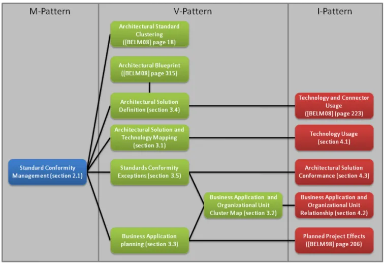
The EAM patterns included in this article are part of a larger pattern language and therefore relationships between EAM patterns are an integral part of this approach. Figure 1 shows a pattern map visualizing these relationships. The patterns are referenced by their names, page numbers are included in brackets.
3
During the creation of this article the EAM pattern ap-proach has been revised, e.g. the concerns of version 1.0 of theEAM Pattern Catalog have been split up into prob-lems and forces, etc. Therefore, concerns are not explicitly covered in the rest of this article. A typical concern in EA management could be How can licensing costs for business applications and infrastructure be reduced?
2.
METHODOLOGY PATTERNS
M-Patterns are grouped according to their membership to typical EA management topics, like Application
Land-scape Planning, Support of Business Processes, Interface,
Business Object and Service Management, etc. This article
includes one M-Pattern called Standard Conformity Man-agement, which is part of the question complexTechnology Homogeneity
2.1
Standard Conformity Management
Profile
Id M-4
Version 2.0
The M-Pattern Standard Conformity Management defines and manages architectural standards. Analyses on this in-formation may lead to new guidelines concerning architec-tural standards, as well as roadmaps to increase or decrease standard conformity.
2.1.1
Example
As the department storeSoCaStoregrows it collects a va-riety of business applications. Many use obsolete architec-tures and technologies. Some of the systems are retired but often the business support of the systems is too valuable to retire them but too expensive to replace them. Additionally, the high number of different architectures and technologies used in the applications, calls for a high number of experts able to operate and maintain the business applications con-forming to them. Licensing and maintenance costs as well as costs for integrating different technologies are also a critical factor.
2.1.2
Context
An enterprise with a large number of business applications (typically more than 50), which are part of the application landscape and infrastructure software needed to run these business applications.
2.1.3
Problem
You feel the risk of an unmanaged application landscape, with a multitude of technologies, will increase the cost of development of new business applications, operation, evolu-tion and retirement of existing business applicaevolu-tions. You do not know, if the business applications follow a common blueprint or architectural style and what the impact of a change to these standards would be. Typically such a sit-uation appears in large organizations with decentralized IT departments, after mergers and acquisitions, or just because the degree of disorder increases over time. You believe archi-tectural standards will help to reduce risks and costs through more homogeneity.
How do you establish and manage conformity to architectural standards?
The followingforces influence the solution:
• Standard Conformance: Do currently used busi-ness applications correspond to architectural standards? Are deviation reasons documented, e.g. strategic de-cisions?
• Standard Modification: Which activities or projects have to be started in order to improve conformance to architectural standards? Which modifications to the
currently used business applications are necessary to achieve conformity?
• Standard Usage: Where are architectural standards used, and are there areas where those standards are breached?
• Standard Definition: How is an architectural stan-dard (architectural blueprint, architectural solution made, etc.) up?
• Licensing Costs: How can licensing costs for busi-ness applications and infrastructure be reduced?
• Incompatible Technology Risks: How can risks concerning the utilization of incompatible technologies for business applications be reduced?
2.1.4
Solution
Set architectural standards, i.e. developing a set of ar-chitectural blueprints and arar-chitectural solutions, and as-signing them to new and existing business applications, in order to increase efficiency in IT operation and development. Thereby, approved deviations to the standards also have to be documented and managed.
Architectural standards are thereby be divided in
• architectural blueprints, which define, which abstract technologies, like e.g. a relational database system, may be used for new business application and in
• architectural solutions, which are like an instantiation of an architectural blueprint with concrete technolo-gies, like e.g. an Oracle 9i database.
Architectural solutions and architectural blueprints con-sider homogeneity not only on the level of a specific kind of technology e.g. programming languages or middleware, but include architectural solutions and consider technologies at the level of standardized technologybundles.
After architectural standards have been set, activities and projects for improving conformance to the standards can be derived, which may then enter project portfolio management as proposals.
Setting
Standards
Analyzing
Standards
Enforcing
Standards
Evaluate
Standards
Figure 2: Management process for Standard Con-formity Management
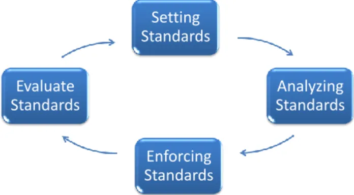
Subsequently, the four steps of the methodology are de-scribed: Firstly setting architectural standards is consid-ered, which afterwards have to be analyzed concerning stan-dard conformity for specific business applications or subsets
of the application landscape. This is followed by an en-forcement of the defined standards, which at last have to be evaluated if they are still feasible in the company under consideration. To complete the cyclic process of Standard Conformity Management (see Figure 2), architectural stan-dards which are no longer feasible have to be adapted or new standards have to be created.
The implementation section of this I-Pattern will addi-tionally cover the aspect of involving the right people and establishing the right governance structures.
2.1.5
Setting Standards: Creating Architectural
Blueprints and Architectural Solutions
Before setting specific architectural standards, it is nec-essary to decide, what these standards should encompass. Possibilities here are e.g.:
• The components (deployed and running sub-systems) a business application may consists of, and how these may communicate (connectors).
• The infrastructure software, which the components rely on.
• The hardware running the components.
• Development environments used for developing the re-spective software.
The EAMVS online survey [5] showed that the first two items are most important to practitioners.4 Thereby, the first and the second item can be addressed by architectural blueprints and solutions. Understood this way, an archi-tectural blueprint is an exemplary description of a software architecture in the component-and-connector viewtype ac-cording to [9]. This leads to different possible notations for
defining architectural blueprints:
• We propose V-Pattern Architectural Solution Defini-tion(see section 3.4), which is based on the respective UML-notation in [9].
• V-PatternArchitectural Blueprint(see page 315 in [5]) is a possible alternative to V-PatternArchitectural So-lution Definition, but this pattern was evaluated in the EAMVS to be of minor importance.
• The architectural description language ACME [15] is another possibility.
However, the description of the exemplary architecture in an architectural blueprint is technology-neutral. The spe-cific technologies are set when an architectural solution is created based on a specific architectural blueprint, which assigns aspecific technology to each so calledabstract
tech-nologyin the architectural solution. Using this approach is
reasonable, because specific technologies change more often then abstract technologies. This distinction offers the possi-bility to define more stable architectural standards based on architectural blueprints. In this case architectural solutions can be seen as a way to document which specific technologies work well together.
4
Ranked by practitioners regarding importance on a 1-5 Lik-ert scale (5 is most important), they received an average rating of 4 or more.
Several aspects may influence which and how many archi-tectural standards are offered.
The following arguments are in favor for architectural standards:
• Projects may choose an architecture and technologies they regard to be most suitable for the respective tasks, without having to ”reinvent the wheel”.
• Architectural standards document proven practices in combining technologies to fulfill certain tasks.
• Architectural standards may be used to reduce the het-erogeneity of the application landscape.
• Knowledge about an additional architecture has to be kept available, if the business application does not con-form to defined standards, at least as long as it is op-erated.
• Knowledge about technologies is only needed for al-lowed technologies.
In contrast the following arguments are against architec-tural standard:
• It may be easier and faster to develop a business ap-plication exactly satisfying its requirements without following the defined standard architecture.
The set of offered standards has to strike a balance be-tween these effects.
2.1.6
Analyzing Standards: Analyzing Standard
Con-formity of Business Applications
First, create an overview of which business application uses which architectural solution and analyze it. For col-lecting this information, it is important to know that the employees operating a business application might not always be aware of its architecture. Thus, developers might have to be included into the data collection process. Of course, up-to-date architectural blueprint and solution definitions are a prerequisite for this task. Additionally, an understanding of the blueprints should exist among the developers. This can be facilitated by using V-Patterns likeArchitectural Solution Definition (see section 3.4).
The collected information should then be verified. Here also different possibilities apply, ranging from automated plausibility checks to manual reviews, which could be tied to visualization creation. If necessary, missing or possibly erroneous information has to be delivered in addition or cor-rected.
AnArchitectural Solution and Technology Mapping-diagram
(see section 3.1) can provide background information about the existing architectural blueprints and solutions. It can give a first overview of the technologies included in a stan-dard. This allows a first stage of the analysis: The set of standards might be too small (too restrictive) or too big (too permissive).
Next, analyze the application landscape to find business applications that do not belong to an architectural standard. This can e.g. be done by highlighting such business appli-cations. For example, useStandards Conformity Exceptions
(see section 3.5) andArchitectural Standard Clustering (see page 101 in [5]). Standards Conformity Exceptions can in-dicate where architectural standards are met, where this is
not the case, and where breaking the standard is specifically allowed.
Utilizing these two V-Patterns, the focus is likely to be on the business applications not conforming to the respec-tive architectural standard. On the one hand, such business applications might be looked at specifically, considering e.g.:
• Does it require not to conform with the standard?
• How much costs are thus induced? Who bears these costs?
• Has the wrong standard been prescribed for the busi-ness application?
On the other hand, analyses can also focus on the totality of the non-conforming business applications, e.g. looking at:
• What do they have in common?
• Are the standards inadequate for important parts of the application landscape?
• Are there organizational units for which there are no means of enforcing the standards?
Especially an Architectural Standard Clustering-diagram (see page 101 in [5]) might be helpful in getting an impres-sion of the importance of the different architectural solu-tions. A standard only existing to serve a small proportion of the business applications might need a special justifica-tion.
Breaking standards can e.g. be allowed if significant busi-ness success is tied to the possibility to have projects outside the respective standards. However, this introduces the issue of who receives the benefits derived from breaking the stan-dard, and who bears the costs induced thereby.
2.1.7
Enforcing Standards: Deriving Measures for
Increasing Homogeneity
Once architectural standards are set, measures for im-proving conformance have to be developed and discussed. Certainly, such measures are described in a detailed, textual way by the architectural standard control group. However, diagrams like V-PatternBusiness Application Planning(see section 3.3) can give an overview of the changes in the ap-plication landscape due to a (specific) proposed measure.
Deriving measures involves finding the non-conforming business applications e.g. via analyzes as described above. Based on this, the reasons for the business applications non-conforming to the standards can be determined. This sets the ground for deciding, whether a specific business appli-cation currently not conforming to the standards has to be changed. Subsequent points might be important in such a discussion:
• Has the wrong standard been set for a business appli-cation? In this case, the standard should be changed.
• If there is excessive cost for standard conformance, an exception could be sensible.
• If the benefit of conforming to the standard cannot be realized in a specific situation, this might also be a reason for an exception.
If it is decided that one or more business applications have to be changed, the respective proposal has to be created, and can then be entered into project portfolio management, if available, or an equivalent management process.
2.1.8
Evaluate Standards: Find Standards which have
to be Adapted
The stepssetting standards,analyzing standards, and
en-forcing standardsare not sufficient for a continuous
manage-ment approach. As requiremanage-ments and technologies change over time, the standards, which are currently in use, have to be evaluated concerning their applicability in the future. There are different ways to achieve such an evaluation. A simple approach would be to count how often a certain standard is in use. If this value is below a certain threshold, an in depth analysis should initiated why the standard is only seldomly used. One reason could be that the standard has been created for specific requirements. In this case the standard need not be revised. Another reason could be that the standard uses a technology which is no longer considered to be state of the art. In this case the standard should be changed or retired.
More sophisticated approaches, like technology roadmaps defining the upgrade paths for technologies that may be used in standard definitions could also be used but require higher efforts to be realized.
2.1.9
Implementation
In order to implement this M-Pattern within an organiza-tion it is very important to create the required governance structures and to involve the right people, meaning that it is required to establish a group of people, which are able to de-fine the required architectural standards. This group of peo-ple is called the Architectural Standard Group and usually recruits its members from the software architect and from the enterprise architect group of the company, as knowledge about technologies and their interrelations is required. See
Architect Also Implements in [10] for detailed information
about this topic.
Only defining the standards usually is not enough as it is required that these standards are controlled and if neces-sary are enforced. This should be done by a special group of enterprise architects, theArchitectural Standard Control
Group, which should be incorporated in every project
ex-ceeding a certain project cost limit. The limit is depending on the size of the company and the budget available for EA management.
A third group of people is required for escalation. This group, theArchitectural Standard Board, should be on board level and should incorporate members of the business as well as of the IT part of the company. If no consensus between the project and the architectural standard group is possible, the architectural standard board has to decide if breaking a standard is allowed or not. The enforcement of this de-cision may also influence the budget of the project under consideration.
2.1.10
Known Uses
The approach documented in M-Pattern Standard
Con-formity Managementis in use in the following companies:
• BMW Group
• HVB
• Enterprise Architecture Management Tool Survey 2008
/ SoCaStore (sebis)
The approach documented in this M-Pattern can be used in the following EA management tools
• ARIS (IDS Scheer AG)
• planningIT (alfabet AG)
The pattern is also known asManagement of Architectural
Standards andBlueprint Conformity Management.
2.1.11
Consequences
It is helpful, if not necessary for the M-Pattern, that ar-chitectural solutions areboundary objectsbetween enterprise architects and software architects. These two domains need an aligned understanding of the architectural standards, en-abling them to efficiently communicate in using them.
A boundary object is an object, which allows members of different communities to build a shared understanding in respect to certain things. Boundary objects are interpreted differently by the different communities, and realizing as well as discussing these differences leads to a shared understand-ing [25, 26].
If architectural standards are to be beneficial, there has to be an entity having both power and commitment to enforce the standards as described in the implementation section. This entity is then likely to be also in charge of allowing exceptions from the standards. Thereby, it has to address the problem that the benefit and the costs of conforming to blueprints and solutions occur in different places:
• It is likely that the costs for conforming to an architec-tural standard occur directly in the development team or operators responsible for the respective application (in the short term). Costs can also occur at users, if a conforming business application is less suitable, e.g. due to decreased performance, which is not improvable without a highly specialized architecture.
• The benefit of increased homogeneity are likely to be of a more long-term nature, and occur primarily with the IT departments responsible for operating and de-veloping business applications. However, if more ef-ficient development can lead to a more swift project execution, business might be able to benefit from a reduced time to market.
If the decision process is not able to balance this on a cross-organizational level, it might happen that decisions are locally optimal for specific organizational units, but subop-timal for the organization as a whole. An example for an approach trying to balance the aspects is allowing deviations from the standard, but estimating the future effort of fixing issues created by this, and imposing a respective fee on the organizational unit that demands breaking the standard.
Another consequence is that defined architectural stan-dards have to be maintained and evolved to keep up with
new technologies, developments, etc. On the one hand this has a positive effect as there is a need to continually re-think defined solutions resulting in a potential improvement of the defined standards. On the other hand investments are needed to be able to maintain and evolve the standards, which have to be in balanced with the potential savings.
2.1.12
See Also
In order to support the implementation of M-Pattern
Stan-dard Conformity Managementthe following V-Patterns should
be considered:
• Architectural Standard Clustering(see page 101 in [5])
• Architectural Solution and Technology Mapping (see
section 3.1)
• Business Application Planning(see section 3.3)
• Architectural Solution Definition (see section 3.4)
• Standards Conformity Exceptions(see section 3.5)
• The architectural description language ACME [15]
3.
VIEWPOINT PATTERNS
This section contains the following selection of V-Patterns, which are part of theEAM Pattern Catalog [5].
• Architectural Solution and Technology Mapping (see section 3.1)
• Business Application and Organizational Unit Cluster Map (see section 3.2)
• Business Application Planning (see section 3.3)
• Architectural Solution Definition (see section 3.4)
• Standards Conformity Exceptions (see section 3.5)
3.1
Architectural Solution and Technology
Mapping
Profile
Id V-23
Version 2.0
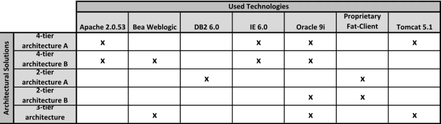
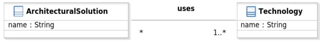
This V-Pattern consists of a table containing the technolo-gies used in architectural solutions.
3.1.1
Example
The application landscape of SoCaStore has evolved over the years to fulfill new business demands as quickly as possi-ble. To achieve the required speed to support these demands new business applications have been developed without car-ing about selectcar-ing technologies for the new business ap-plication or defining architectural solutions. This approach resulted in a lack of information and knowledge about the technologies used in the company. In order to change this situation visualizations are needed to give an overview about the dependencies between the operated business applica-tions and the technologies they are built upon.
3.1.2
Context
Getting and maintaining an overview about the technolo-gies, which build up architectural solutions is difficult in large companies.
Apache 2.0.53 Bea Weblogic DB2 6.0 IE 6.0 Oracle 9i Proprietary Fat-Client Tomcat 5.1 4-tier architecture A
x
x
x
x
4-tier architecture Bx
x
x
x
2-tier architecture Ax
x
2-tier architecture Bx
x
3-tier architecturex
x
x
A rch itec tu ra l Sol u ti o n s Used TechnologiesFigure 3: Exemplary view for V-PatternArchitectural Solution and Technology Mapping
3.1.3
Problem
You want to reduce costs and security risks by limiting the number of technologies used to implement business ap-plications. To reduce their number, you first have to know what technologies are in use and where.
How do you visualize technology usage of business applications in a concise manner?
The followingforces influence the solution:
• Impact Analysis: How do you get easy visual feed-back of impact analysis?
• Popular Technologies: How do you spot popular technologies or trends, as these technologies are can-didates for future architectural blueprints?
• Migration Issues: How do you detect problems in migrating from one version of a technology to another or in the evolution of a technology?
• Technology Compability:How do you get an overview about technologies that may be used in combination to prevent compability problems?
3.1.4
Solution
This view consists of a table containing the technologies used in an architectural solution, e.g. a 3-tier architecture. Thereby, an ”X” in a table cell symbolizes the usage rela-tionship. It may be used in different ways. At first you may get an overview about the different technologies used within a company, together with the information, in which architectural solution the technologies are utilized.
At second you can use the V-Pattern to perform impact analysis. Therefore, you select a technology, which will e.g. be changed or replaced, and you can then see the affected architectural solutions.
As the number of different technologies and architectural solutions in use within a company may be high it may be useful to filter the information visualized, e.g. to select a technology and fade out all architectural solutions, which do not use it, in order to support the user in performing the impact analysis.
3.1.5
Implementation
This V-Pattern can be implemented in a spreadsheet tool or, if a graph representation (see variants section) is chosen,
in a graph layout tool. If filtering should be used, than this functionality should be supported by the tool.
3.1.6
Variants
Different variants for this V-Pattern exist. The informa-tion shown in Figure 3 could also be shown as a simple textual report, listing the technologies for an architectural solution. Another possible visualization would be a simple graph, where technologies and architectural solutions are represented by nodes and the usage of a technology in an architectural solution is visualized by an edge connecting the respective nodes.
The same kind of viewpoint can be created for architec-tural blueprints and abstract technologies. In these cases the same alternatives, textual listing, graph visualization, etc. apply.
3.1.7
Known Uses
The following companies use this V-Pattern:
• HVB
Views according to this V-Pattern can be created, e.g. using the following EA management tools:
• alphabet (planningIT AG)
• ARIS (IDS Scheer AG)
• System Architect (IBM)
• SoCaTool (sebis)
3.1.8
Consequences
The benefit of this V-Pattern is its simplicity. A simple table or graph is sufficient to address the problem described in the problem section. On the one hand these kinds of vi-sualizations can easily be created on the other hand they can very intuitively be used to reduce the number of tech-nologies, if variants or version differences can be eliminated. Additionally, you can get a gist of the impact of such a technology elimination and it is easier to spot the impact of required technology changes, i.e. because of security issues.
3.1.9
See Also
This V-Pattern may be useful when using M-Pattern
Stan-dard Conformity Management (see section 2.1). The
visu-alized information is based on I-Pattern Technology Usage
3.2
Business Application and Organizational
Unit Cluster Map
Profile
Id V-24
Version 2.0
This V-Pattern visualizes relationships between business ap-plications and organizational units by using the concept of clustering.
3.2.1
Example
The application landscape of SoCaStore has continually grown since the foundation of SoCaStore. In the next few months a new subsidiary should be established in Hong Kong, which demands for an appropriate IT support. Using already existing business applications is a solution, which is time- and cost-saving. In order to prepare the business applications for their new tasks it is important to know where they are hosted, who uses them, who is responsible for them, etc. Unfortunately, this overview about the ap-plication landscape is not available through the continually growth of SoCaStore and now has to be regained.
3.2.2
Context
In an enterprise with a large number of business applica-tion it is hard to judge who is responsible for running them or who benefits or suffers from changes applied to them.
3.2.3
Problem
Relationships between business applications and organi-zation units are of importance, e.g. when trying to analyze and determine responsibilities, utilizations, etc. for business applications.
Which relationships exist between business appli-cations and organizational units and how can you visualize them?
The followingforces influence the solution:
• Visualize Responsibilities: How do you visualize responsibilities for business applications in order to ex-plicate them?
• Visualize Usage: How do you visualize the usage of business applications?.
• Visualize Operation: What is a distinct and easy to understand visualization to show where business appli-cations are hosted?
3.2.4
Solution
This V-Pattern belongs to the software map typeCluster Map, which uses the concept of grouping (clustering) of el-ements in a visualization to express a relationship between them. The positioning of the different clusters is of minor importance as it does not transport any semantic informa-tion, but may be used to improve recognition like organiza-tional unit headquarter is always positioned in the top left corner.
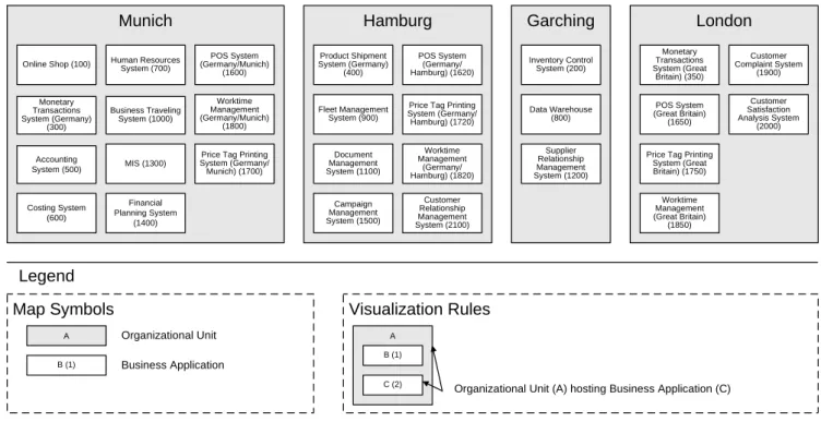
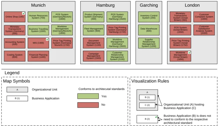
In this V-Pattern a cluster map like viewpoint is used to group business applications in organizational units. Fig-ure 4 exemplarily visualizes a hosting relationship. This is only one possible semantic for the relationship between busi-ness applications and organizational units, additional vari-ants are described in the varivari-ants section of this V-Pattern.
A business application may appear multiple times within a view corresponding to this V-Pattern, e.g. if it is used by multiple organizational units.
Different kinds of usages are supported by this V-Pattern. First of all it is possible to give an overview, about the as-is situation, or about planned and target scenarios of the ap-plication landscape, when incorporating the aspect of time. Secondly, it is possible to do extended analyzes, like e.g. impact analysis concerning redundantly hosted business ap-plications, etc.
3.2.5
Implementation
Views according to this viewpoint can be created manu-ally by any drawing tool, like e.g. Microsoft PowerPoint. As manual creation is time consuming and error prone it is ad-vised to use a tool, like the ones listed in the implementation section to automatically generate the visualization.
3.2.6
Variants
Additional variants for this V-Pattern exist, as different semantics are possible for the relationship between business applications and organizational units. Three exemplary ones are listed below:
• Organizational unithostsbusiness application
• Organizational unitusesbusiness application
• Organizational unit is responsible for business appli-cation
Each of these possibilities results in a variant of the V-Pattern. Thereby, the clustering of elements is used to rep-resent the different relationships.
3.2.7
Known Uses
The following uses are known:
• Enterprise Architecture Management Tool Survey 2008
/ SoCaStore (sebis)
• Klinikum der Universit¨at M¨unchen
• Munich Re
Views according to this V-Pattern can automatically be created, e.g. using the following EA management tools:
• alphabet (planningIT AG)
• ARIS (IDS Scheer AG)
• Iteraplan (Iteratec)
• SoCaTool (sebis)
This pattern is also known asUsing Relationship
Clus-ter Map, Hosting Relationship Cluster Map, Responsibility
Relationship Cluster Map.
3.2.8
Consequences
A benefit of this V-Pattern is that it is a good starting point for EA management activities and supports many dif-ferent analyzes. Two exemplary analyzes are e.g. find orga-nizational units with(out) intensive relationships to business
applications and find responsibilities for business
Munich
Hamburg
Garching
London
Online Shop (100) Inventory Control System (200)
Monetary Transactions System (Germany) (300) Monetary Transactions System (Great Britain) (350) Product Shipment System (Germany) (400) Accounting System (500) Costing System (600) Human Resources System (700) Data Warehouse (800) Fleet Management System (900) Business Traveling System (1000) Document Management System (1100) Supplier Relationship Management System (1200) MIS (1300) Financial Planning System (1400) POS System (Germany/Munich) (1600) Campaign Management System (1500) POS System (Germany/ Hamburg) (1620) POS System (Great Britain) (1650)
Price Tag Printing System (Germany/ Munich) (1700)
Price Tag Printing System (Germany/ Hamburg) (1720)
Price Tag Printing System (Great Britain) (1750) Worktime Management (Germany/Munich) (1800) Worktime Management (Germany/ Hamburg) (1820) Worktime Management (Great Britain) (1850) Customer Relationship Management System (2100) Customer Complaint System (1900) Customer Satisfaction Analysis System (2000)
Map Symbols
Visualization Rules
Legend
A Organizational Unit
B (1) Business Application
A B (1)
C (2) Organizational Unit (A) hosting Business Application (C)
Figure 4: Exemplary view for V-PatternBusiness Application and Organizational Unit Cluster Map
Views according to this V-Pattern can easily be explained and used, and contain a lot of valuable information about the current situation of the application landscape. In addi-tion they may also be used for planning aspects.
Additionally, the creation of views corresponding to this V-Pattern is simple and can even be done manually in some kind of drawing tool in the last resort. Furthermore, the amount of information that has to be collected is limited.
Another benefit is that this kind of visualization can easily be enriched by additional layers providing additional infor-mation, like costs for maintaining the business applications, connections between business applications, etc. Refer to the next section for further details.
3.2.9
See Also
The V-Pattern is based on information according to I-PatternBusiness Application and Organizational Unit Re-lationship(see section 4.2) and its variants.
Additionally, V-Pattern Business Application and
Orga-nizational Unit Cluster Mapis the basis for all V-Patterns,
which rely on visualizing the relationship between business applications and organizational units together with other information. The following list provides an overview about these V-Patterns.
• Business Application Planning (see section 3.3)
• Standards Conformity Exceptions (see section 3.5)
3.3
Business Application Planning
Profile
Id V-39
Version 2.0
This V-Pattern visualizes changes to business applications or the introduction of new ones using a color coding. It can be used to perform application landscape planning.
3.3.1
Example
SoCaStore wants to start an initiative to consolidate its application landscape. Therefore, existing business applica-tions have to be modified or retired and new ones have to be introduced. This is only possible, if an overview about the application landscape and the planned changes is available.
3.3.2
Context
In a large application landscape the future development, e.g. the introduction of a new business application or the phase out of existing one, has to be planned.
3.3.3
Problem
You want to plan the evolution of the business applica-tions, which make up the application landscape. To do this, you need to know which business applications have to be introduced, changed, shut down, or are not changed at all. Additionally, the relationships between the business applica-tions and the organizational units are of importance, e.g. to find the responsible person for an organizational unit with a lot of upcoming changes in order to discuss the consequences of these changes.
How do you visualize the life cycle status of the business applications in order to get a quick overview?
The followingforces influence the solution:
• Affected Organizational Units:How do you iden-tify organizational units where a lot of changes take place and which are not at all affected?
• Planning Conflicts: What conflicts exist in the cur-rent development plan of the application landscape?
• Explicate Planned Changes: How can effects of future changes to business applications be explicated in a clear and simple way?
Munich
Hamburg
Garching
London
Online Shop (100) Inventory Control System (200) Monetary Transactions System (Germany) (300) Monetary Transactions System (Great Britain) (350) Product Shipment System (Germany) (400) Accounting System (500) Costing System (600) Human Resources System (700) Data Warehouse (800) Fleet Management System (900) Business Traveling System (1000) Document Management System (1100) Supplier Relationship Management System (1200) MIS (1300) Financial Planning System (1400) POS System (Germany/Munich) (1600) Campaign Management System (1500) POS System (Germany/ Hamburg) (1620) POS System (Great Britain) (1650) Price Tag Printing
System (Germany/ Munich) (1700)
Price Tag Printing System (Germany/ Hamburg) (1720)
Price Tag Printing System (Great Britain) (1750) Worktime Management (Germany/Munich) (1800) Worktime Management (Germany/ Hamburg) (1820) Worktime Management (Great Britain) (1850) Customer Relationship Management System (2100) Customer Complaint System (1900) Customer Satisfaction Analysis System (2000)
Map Symbols
Legend
A Organizational UnitB (1) Business Application B (1) New Business Application B (1) B (1) Replaced by another Business Application Business Application is modified A B (1)
C (2) Organizational Unit (A)
hosting Business Application (C)
Visualization Rules
Status of Business ApplicationFigure 5: Exemplary view for V-PatternBusiness Application Planning
3.3.4
Solution
This V-Pattern uses the concept of a cluster map showing a relationship between business applications and organiza-tional units, based on the V-PatternBusiness Application
and Organizational Unit Cluster Mapand its variants.
The exemplary visualization in Figure 5 depicts the host-ing relationship. In addition to this relationship the V-Pattern indicates, which business applications are to be changed, by highlighting these business applications. Normally, these changes can be traced back to a project, offering informa-tion about the type of change that has to be performed, e.g. that a business application has to be replaced by another one. The type of change is indicated by different colors, like explicated in the legend of Figure 3.3.
3.3.5
Implementation
The information about the type of change that that has to be performed on the business application should be vi-sualized on a different layer than the relationship between organizational units and business application to be able to profit from the layering principle5.
When there is a demand to utilize the layering concept, it is advised to use a tool supporting this functionality.
3.3.6
Variants
There are many different semantics for the relationship be-tween business applications and organizational units. Each of them constitutes a different variant of this V-Pattern.
Additionally, the information, which business applications are affected by changes can be visualized on a different soft-ware map type, like a Cartesian map, in particular a process
5
See [12] for more details on the layering principle.
support map. V-PatternProcess Support Map(see page 105 in [5]) gives more information about this kind of software map type. The additional relationship to business processes offers the possibility for extended analyses, like an analy-sis which business processes are primarily effected by the planned changes and which ones do not have to be consid-ered.
The variants mentioned above may also consider a time aspect, meaning that the visualization of the application landscape will look different, if it e.g. shows the status for today or the status in a year from now.
3.3.7
Known Uses
The following uses are known:
• Enterprise Architecture Management Tool Survey 2008
/ SoCaStore (sebis)
Views according to this V-Pattern can automatically be created, e.g. using the following EA management tools:
• alphabet (planningIT AG)
• ARIS (IDS Scheer AG)
• SoCaTool (sebis)
3.3.8
Consequences
Normally, a business application can only be changed by a project, resulting in a need to also collect information about the project itself and not only about the scheduled changes for the business applications.
If tracing back the changes on a business application to a project is needed, it is advisable to have additional informa-tion about this project available, e.g. in a textual form, for further analyses.
Considering time aspects demands for additional infor-mation, e.g. about the start time and duration of a project changing a business application. Therefore, another I-Pattern is needed to fulfill this additional demand.
3.3.9
See Also
Creating views based on this V-Pattern requires to collect information according to I-PatternPlanned Project Effects
(see page 206 in [5]) to visualize which business applications have to be changed due to which projects. Additionally, information about the relationships between the business applications and the organizational units can be gained by I-PatternBusiness Application and Organizational Unit Re-lationship(see section 4.2) or its alternatives.
3.4
Architectural Solution Definition
Profile
Id V-66
Version 2.0
This V-Pattern uses an UML 2.0 object diagram to visu-alize an architectural solution and the technologies used.
3.4.1
Example
Due to the uncontrolled evolution of SoCaStore’s business applications a multitude of different architectures are in use and are planned for future developments. This should be prevented in the future by providing defined and obligatory architectural standards. In order to define this architectural standards in a standardized way a defined notation has to be used.
3.4.2
Context
Defining architectural standards and maintaining them is difficult, if various architectural standards and different no-tations are in use.
3.4.3
Problem
You want to increase homogeneity of business applica-tions’ architectures by using defined architectural standards. In order to achieve this goal you have to decide for an oblig-atory notation for defining and maintaining architectural standards.
What visualization should be used to define and manage architectural solutions for business applica-tions?
The followingforces influence the solution:
• Standard Definition Overview: How do you get an overview about defined architectural standards?
• Plain Notation: What notation for architectural stan-dards is distinct and easily understandable?
3.4.4
Solution
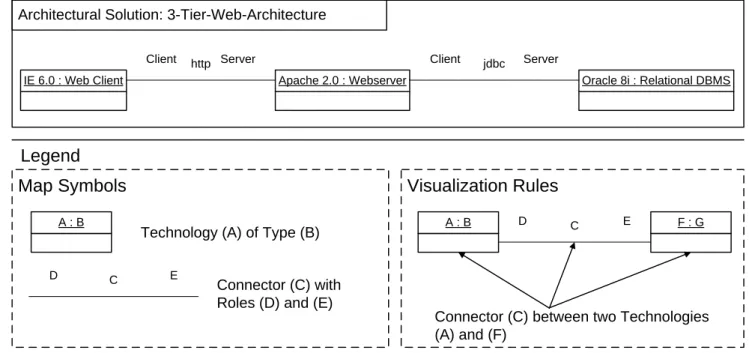
V-Pattern Architectural Solution Definition uses the no-tation of an UML 2.0 object diagram to visualize the struc-ture of anarchitectural solution. An architectural solution includes the allowed technologies, like e.g. Apache 2.0, In-ternet Explorer 6.0, etc. and the allowed connectors between these technologies, e.g. an http connection used between the Internet Explorer 6.0 and the Apache 2.0. An example of a view defining an architectural solution is given in Figure 6.
3.4.5
Implementation
Views, which are based on this V-Pattern may be created using an UML modeling tool, in order to use the syntactic checking incorporated in the tools. When using a variant not relying on the UML notation any kind of drawing tool may be used.
3.4.6
Variants
A variant of this V-Pattern is concerned about
Archi-tectural Blueprints. Thereby, the architectural solution is
an instantiation of an architectural blueprint, which defines which abstract technologies, e.g. a web client, a web server, etc. may be used and in which combination.
Both variants can also be combined, meaning that infor-mation about technologies and about abstract technologies is shown within one visualization. See consequence section for more information.
A second variant would be to abstain from the notation of UML 2.0 object diagram. Whereas, this has the advantage, that the views can be drawn with any visualization tool, this leads to the problem that drawing without defined syntactics and semantics may result in misleading views.
3.4.7
Known Uses
The following uses are known:
• BMW
Views according to this V-Pattern can automatically be created, e.g. using the following EA management tools:
• ARIS (IDS Scheer AG)
• Rational Software Architect (IBM)
• System Architect (IBM)
This pattern is also known asArchitectural Blueprint Def-inition.
3.4.8
Consequences
Visualizing information about an architectural solution and the associated blueprint in one visualization may lead to large and hard to understand views. Therefore, it may be reasonable to omit information about the architectural blueprint or the architectural solution.
A benefit of this V-Pattern is that it is easily understand-able by different groups, like software architects, enterprise architects, etc. within the company this improves commu-nication between them. Besides the easy understandability of visualizations according to this V-Pattern, they are ex-tensive enough to avoid misleading interpretation and uti-lization.
3.4.9
See Also
Another V-Pattern, calledArchitectural Blueprint(see page 315 in [5]) is also focused on defining architectural blueprints utilizing but also incorporates the concept of tiers to sepa-rate different layers of the architecture.
Creating views based on this V-Pattern requires to collect information according to I-PatternTechnology and Connec-tor Usage(see page 223 in [5]) to visualize, the relationships between technologies, connectors, and abstract technologies.
IE 6.0 : Web Client Apache 2.0 : Webserver Oracle 8i : Relational DBMS Client http Server Client jdbc Server
A : B D C E
Legend
Technology (A) of Type (B)
Visualization Rules
A : B F : G
D C E
Connector (C) between two Technologies (A) and (F)
Connector (C) with Roles (D) and (E)
Map Symbols
Architectural Solution: 3-Tier-Web-Architecture
Figure 6: Exemplary view for V-PatternArchitectural Solution Definition
3.5
Standards Conformity Exceptions
Profile
Id V-67
Version 2.0
This V-Pattern shows which business applications conform to architectural standards, and where exceptions from these standards have been allowed. This information is combined with information about the relationships between business applications and organizational units.
3.5.1
Example
SoCaStore is using the concept of architectural blueprints and architectural solutions for a few months now, but the effects of this concept, like standardization of the application landscape, etc., have not yet been analyzed. To conduct such analyzes visualizations are needed, which not only show the standard conformity of the application landscape, but also the allowed exceptions.
3.5.2
Context
It is hard to analyze the standards conformity of business applications if the application landscape exceeds a certain size. Usually this happens if more than 100 business applica-tions have to be considered. It gets even worse if excepapplica-tions to defined standards have to be regarded.
3.5.3
Problem
You want to reduce costs by increasing the degree of stan-dardization of the application landscape. To achieve this you first have to get an overview of the application landscape and its current use of standards. Before you can begin to adopt the business application not conforming to standards, you have to consider whether there should be exceptions.
How do you visualize an overview about the stan-dardization of the application landscape, also includ-ing information about allowed exceptions?
The followingforces influence the solution:
• Exception Overview: How to get an overview about allowed exceptions to architectural standards?
• Identify White Spots: How to identify organiza-tional units where there is no information available about the standardization of business applications?
• Identify Outstanding Organizational Units: How to find organizational units with an exceptionally high amount of (not) standardize business applications?
3.5.4
Solution
This V-Pattern uses the same concept – a cluster map – as its base, as V-PatternBusiness Application and
Organi-zational Unit Cluster Map (see section 3.2), resulting in the
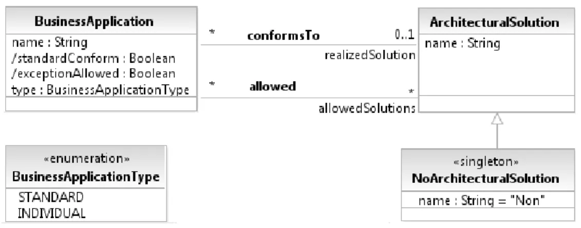
same variety of semantics that can be used. In this case a layer is added to the cluster map showing, which business applications conform to architectural standards, and where exceptions from these standards are tolerated. Using the cluster map concept here is favorable as it provides a good and intuitive overview about the relationships described be-fore.
Figure 7 shows these relationships via an exemplary clus-ter map, based on the hosting relationship between business applications and organizational units.
Conformance to architectural standards is visualized by colors, permitted exceptions to these standards are marked by a checkmark.
3.5.5
Implementation
You should use a tool supporting layers for implement-ing this V-Pattern. This offers the possibility to show the information about the type of change that has to be per-formed on the business application on a different layer than the conformance to architectural standards. In this case the amount of information shown in the view can be adapted to specific requirements by showing or hiding layers.
Conforms to architecutal standards
Munich
Hamburg
Garching
London
Online Shop (100) Inventory Control System (200) Monetary Transactions System (Germany) (300) Monetary Transactions System (Great Britain) (350) Product Shipment System (Germany) (400) Accounting System (500) Costing System (600) Human Resources System (700) Data Warehouse (800) Fleet Management System (900) Business Traveling System (1000) Document Management System (1100) Supplier Relationship Management System (1200) MIS (1300) Financial Planning System (1400) POS System (Germany/Munich) (1600) Campaign Management System (1500) POS System (Germany/ Hamburg) (1620) POS System (Great Britain) (1650) Price Tag Printing
System (Germany/ Munich) (1700)
Price Tag Printing System (Germany/ Hamburg) (1720)
Price Tag Printing System (Great Britain) (1750) Worktime Management (Germany/Munich) (1800) Worktime Management (Germany/ Hamburg) (1820) Worktime Management (Great Britain) (1850) Customer Relationship Management System (2100) Customer Complaint System (1900) Customer Satisfaction Analysis System (2000)
Map Symbols
Legend
A Organizational UnitB (1) Business Application Yes No
A B (1)
C (2) Organizational Unit (A) hosting
Business Application (C)
Visualization Rules
Business Application (B) is does not need to conform to the respective architectural standard
B (2)
Figure 7: Exemplary view for V-PatternStandards Conformity Exceptions
3.5.6
Variants
As already mentioned in the solution section different se-mantics for the relationship between business applications and organizational units exist. Each of them constitutes a different variant of this V-Pattern. See V-PatternBusiness
Application and Organizational Unit Cluster Map (see
sec-tion 3.2) for more informasec-tion.
Additionally the information, which business applications are affected by changes can be visualized on a different soft-ware map type, like aCartesian Map, in particular a process support map. V-PatternProcess Support Map(see page 105 in [5]) additionally offers the possibility to analyze the stan-dardization of business applications in respect to business processes.
In contrast to Figure 7 it would also be possible to visu-alize the exceptions to architectural standards on an addi-tional layer. This makes it possible to hide this information as long as it is not needed, leading to an easier to interpret view.
If the information about exceptions is not important for analyses within a company then omit it, because it may lead to overwhelming visualizations resulting in misinter-pretations.
3.5.7
Known Uses
The following uses are known:
• Enterprise Architecture Management Tool Survey 2008
/ SoCaStore (sebis)
Views according to this V-Pattern can automatically be created, e.g. using the following EA management tools:
• planningIT (alfabet AG)
• SoCaTool (sebis)
3.5.8
Consequences
Documentation for an exception to an architectural stan-dard should explain why the exception is tolerated, e.g. in a separate document, in order to support additional analyses and next steps. This nevertheless comprises the disadvan-tage that the required information has to be collected and maintained.
If the information about allowed exceptions to architec-tural standards is not of importance, it should not be vi-sualized, resulting in a reduced amount of information that has to be collected to be able to create the visualization.
A benefit of this V-Pattern is that organizational units, or business processes in case a process support map is used, with a high number of business applications not conforming to architectural standards can easily be found and the addi-tionally included information about the allowed exceptions facilitates the identification of business applications where you should start to increase the standardization.
3.5.9
See Also
Creating views based on this V-Pattern requires to col-lect information according to I-PatternArchitectural
Solu-tion Conformance (see section 4.3) to visualize, which
busi-ness applications do, or do not conform to architectural stan-dards, together with the information where exceptions are tolerated. Additionally, information about the relationships between the business applications and the organizational units can be gained by I-PatternBusiness Application and
Organizational Unit Relationship(see section 4.2) or its al-ternatives.
4.
INFORMATION MODEL PATTERNS
This section contains the following selection of I-Patterns, which are part of theEAM Pattern Catalog [5].
• Technology Usage (see section 4.1)
• Business Application and Organizational Unit Rela-tionship (see section 4.2)
• Architectural Solution Conformance (see section 4.3)
4.1
Technology Usage
Profile
Id I-23
Version 2.0
This I-Pattern shows how information about the technolo-gies used in an architectural solution, can be stored.
4.1.1
Example
SoCaStore wants to start an initiative to reduce the num-ber of technologies used within the company. As a first step the technologies, which are currently in use, have to be col-lected. In order to store this information for future usage, an information model has to be created as an implementation basis for a repository.
4.1.2
Context
Getting an overview about which technologies are used by which architectural solution is a good starting point for homogenization of the application landscape. Additionally, this information may be used for documenting the current structure of architectural solutions but also to plan future ones or to document proven practice.
4.1.3
Problem
You want to reduce costs (licensing, maintenance, etc.), increase homogenization for the technologies used in a com-pany or to document proven practice, e.g. which combina-tion of technologies work together well.
What is a proven way to store and maintain in-formation about technologies used in architectural solutions?
The followingforces influence the solution:
• Minimum Effort: How can the effort to document the technologies in use be minimized?
• Usability: How can impact analysis concerning tech-nologies be supported?
4.1.4
Solution
The solution for the problem described above is based on two entities and one relationship, which are defined as follows:
• ArchitecturalSolution: A concrete stack of correspond-ing technologies, which are intended to be used to-gether in realizing business applications, toto-gether with additional information on how to integrate these nologies into an complex architecture. Combining tech-nologies together to an architectural solution among
others indicates, that components created from the technologies are technically suited for interaction and integration.
• Technology: A Technology represents a technical con-stituent of a business application, ranging from an implementation framework or platform to a database management system or user interface toolkit. Exem-plarly technologies may be ”Apache 2.0.53” or ”Oracle 9.2i”.
• ArchitecturalSolution uses Technology: The associa-tionuses indicates, which architectural solution uses which technologies.
4.1.5
Implementation
This I-Pattern may be implemented in any tool (e.g. database management system, EA management tool, etc.) or format (e.g. spreadsheet, XML, etc.) able to store multiple entities and a single relationship.
4.1.6
Variants
The information model fragment shown in Figure 8 may be extended e.g. by additional attributes, like licensing costs for technologies, or more advanced concepts like lifecycles for technologies, as well as for architectural solutions.
4.1.7
Known Uses
The following uses of this I-Pattern are known:
• Enterprise Architecture Management Tool Survey 2008
/ SoCaStore (sebis)
An equivalent information model fragment is included in the following EA management tools:
• ARIS (IDS Scheer AG)
• planningIT (alfabet AG)
• SoCaTool (sebis)
4.1.8
Consequences
A liability of this I-Pattern is the amount of information that has to be collected to be able to perform reasonable analyses, as an architectural solution is typically built up by four or more technologies. If standard conformity analysis is not part of the selected EA management approach, this I-Pattern should be omitted. Validity of the information is another critical aspect of this I-Pattern. Technologies or architectural solutions may already have changed, e.g. new versions have been introduced, before the information about them can beneficially be used.
A benefit of this pattern is that it presents an easy way to document proven practice about which technologies can be used well together. This information may later be used when planning new business application or defining new ar-chitectural standards.
Another benefit is the support for impact analyses con-cerning technologies, e.g. if a technology has to be changed it is easy to find architectural solutions, which are affected by this change.
4.1.9
See Also
V-PatternArchitectural Solution and Technology Mapping
(see section 3.1) may be utilized to perform analyses on in-formation stored according to this I-Pattern.