Experiences from introducing UML-based development
in a large safety-critical project
Bente Anda&Kai Hansen&Ingolf Gullesen&
Hanne Kristin Thorsen
#Springer Science + Business Media, LLC 2006
Editor:Antonia Bertolino
Abstract UML and UML-based development methods have become de facto standards in industry, and there are many claims for the positive effects of modelling object-oriented systems using methods based on UML. However, there is no reported empirical evaluation of UML-based development in large, industrial projects. This paper reports a case study in ABB, a global company with 120,000 employees, conducted to identify immediate benefits as well as difficulties and their causes when introducing UML-based development in large projects. ABB decided to use UML-based development in the company’s system development projects as part of an effort to enable certification according to the IEC 61508 safety standard. A UML-based development method was first applied in a large, international project with 230 system developers, testers and managers. The goal of the project was to build a new version of a safety-critical process control system. Most of the software was embedded. The project members were mostly newcomers to the use of UML. Interviews with 16 system developers and project managers at their sites in Sweden and Norway were conducted to identify the extent to which the introduction of UML-based development had improved their development process. The interviewees had experienced improvements with traceability from requirements to code, design of the code, and development of test cases as well as in communication and documentation. These results thus support claims in the literature regarding improvements that may be obtained through
DOI 10.1007/s10664-006-9020-6
B. Anda (*)
Simula Research Laboratory, P.O. Box 134, NO-1325 Lysaker, Norway e-mail: [email protected]
K. Hansen
:
I. GullesenABB Corporate Research Center, P.O. Box 90, NO-1361 Billingstad, Norway K. Hansen
e-mail: [email protected] I. Gullesen
e-mail: [email protected] H. K. Thorsen
Department of Informatics, University of Oslo, P.O. Box 1080 Blindern, NO-0316 Oslo, Norway
the use of UML. However, the results also show that the positive effects of UML-based development were reduced due to (1) legacy code that it was not feasible to reverse engineer into UML, (2) the distribution of requirements to development teams based on physical units and not on functionality, (3) training that was not particularly adapted to this project and considered too expensive to give to project members not directly involved in development with UML, and (4) a choice of modelling tools with functionality that was not in accordance with the needs of the project. The results from this study should be useful in enabling other UML adopters to have more realistic expectations and a better basis for making project management decisions.
Keywords UML . Model-driven development . Embedded software . Safety-critical software . Case study
1 Introduction
Companies that adopt UML-based development aim to improve their development process and gain, for example, easier communication within the project, improved design of the code, and improved documentation and thus easier future maintenance. In general, there are high costs involved in introducing new software development methods and risks of failure if the method is not adapted. Therefore, there is a need for case studies to increase knowledge about consequences of project managerial decisions in the context of UML-based development, and about which improvements are realistic in different project contexts.
This paper reports a case study conducted on a large development project in the Swedish–Swiss global company ABB. The goal of the project was to create a new version of a safety-critical process control system based on several existing systems. The development took place at four sites in three countries; and 230 developers, testers and managers were involved, of whom approximately 100 used a UML-based development method themselves or read and applied UML documents. Most of them were newcomers to such development. Most of the software was embedded, while the rest was for the Windows platform. There were approximately 1,000 requirements for this system. The company decided to adopt UML-based development and a method was developed in-house to enable certification according to the IEC 61508 safety standard (IEC1998). Previously, there had been no common methodology for the analysis and design of software in the company.
Despite the widespread adoption of UML, there are few reported empirical studies on the effects of UML-based development. A survey of 5,453 scientific articles published in 12 leading software engineering journals and conferences in the decade from 1993 to 2002, identified 113 controlled experiments in which individuals or teams performed one or more software engineering (Sjøberg et al.2005). Four of the experiments investigated different aspects of the use of UML (Cox and Phalp2000; Otero and Dolado2002; Peleg and Dori
2000; Zendler et al.2001). The first investigates the construction of use case models, the second and third investigate the comprehension of UML diagrams, while the fourth compares the concepts of UML with those of two other formalisms. In addition, the usability of UML-diagrams have been investigated in the context of a student project (Agarwal and Sinha 2003), and experiences of applying UML in the development of embedded systems have been reported in (Pettit2004). To the authors’knowledge this is the only empirical evaluation of UML adoption in a large-scale industrial project.
Interviews were conducted with 16 project managers and developers in the project, who represented different sites, different kinds of development and different roles in the project. The interviews were analyzed according to principles from grounded theory, (Strauss and Corbin1998), to ensure that the interviewees’opinions were conveyed systematically. The interviews showed that UML-based development improved traceability, communication, design, documentation and testing, but it was recognized in this project that the improvements were not as great as they could have been, due to difficulties with the use of UML, in particular regarding 1) choice of diagram to use in specific situations, 2) the interfaces between different models, and 3) the level of detail in the models. The results further showed that these difficulties were, at least partially, caused by project decisions with respect to the reverse engineering of legacy code, distribution of requirements to teams, training and mentoring, and choice of modelling tools.
Within ABB, the constraints of the safety standard meant that the teams had to apply the UML-based method rigorously and produce all the required models. Hence, this project represented a rare opportunity to investigate the effects of UML-based development. The main contribution of this paper is, therefore, that it describes improvements and challenges when adopting UML-based development in an industrial environment. Such information may be beneficial to other companies adopting UML.
The remainder of this paper is organized as follows. Section2describes the company, the project and the ABB UML method. Section3describes the research method. Section4
describes the results with respect to improvements. Section 5 describes the results with respect to challenges in the project. Section6discusses the scope and validity of the results. Section7concludes and describes plans for future work.
2 UML-Based Development in the ABB Project
This section describes the company, the project and the UML-based development method that was applied in the project.
2.1 ABB
ABB is a global company that operates in around 100 countries and employs approximately 120,000 people. It is a leader in power and automation technologies, and develops software and hardware for these markets. The company has a large number of development projects, the majority of which require the development of embedded software (with special hardware included).
ABB’s safety products must be certified according to the international standard IEC 61508 in order to be used in plants or installations where the processes used can be dangerous to humans or damage the environment. This standard is becoming a requirement for the process industry and in discrete manufacturing. It is a life-cycle standard and includes requirements pertaining to the methodology of software development.
Before the start of the project reported in this paper there was little common streamlining of software development in the company; a large number of different methods, programming languages and software tools were used. ABB hoped that the introduction of UML-based development would lead to improvements in requirements handling and traceability, improved design of code, fewer defects in the product and reduced overall costs of development.
2.2 The Project
The goal of the project was to develop a new version of a safety-critical system based on several existing systems. The system was to be installed at several locations. Each installation would program its own logic on top of the system delivered by ABB, which is not modified at the installations.
The workforce comprised approximately 230 people located at four sites: two in Sweden, one in Norway and one in Germany. Approximately 100 people were involved in development with UML. The UML-based development method was used at the first three sites. Some of the developers and all the product managers were domain experts. ABB relies on having domain expertise in-house because they sell a complete product to its customers. Safety certifiers, UML experts, quality managers and peer developers (also with domain knowledge) reviewed the UML models at predefined gates in the development process. The development was organized in teams, while testing was mostly done by specialized testers. The team members were mostly newcomers to the use of UML, although some were experienced.
This software project is ABB’s most ambitious project regarding quality assurance in that it followed the requirements of IEC 61508. To ensure that the software operates at a certain minimum safety integration level (SIL level), this standard strongly recommends the use of semi-formal development methods. Consequently, a UML-based development method (the ABB UML method), which qualifies as a semi-formal method according to IEC 61508, was developed by the company (The ABB Instruction 2001; The ABB Guideline2003). In addition, the system components are SIL certified, which implies that the software parts of the components must implement (parts of) the safety requirements so that the whole component can be SIL-certified. These requirements were derived from the requirements for the safety level before the total set of requirements was distributed to the development teams. Thus, from the point of view of the development teams, there was little difference between the safety-related requirements and the functional requirements.
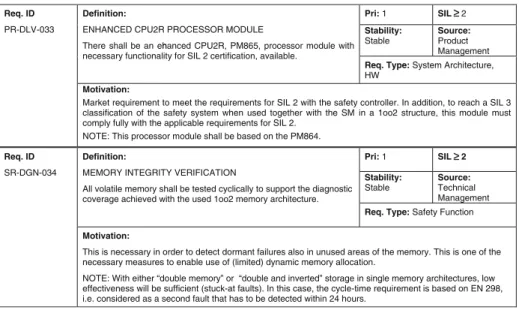
The existing systems consisted of 3–4 million lines of code and there were approximately 1,000 requirements for this version; one third of which concerned satisfying safety requirements, while the remainder consisted of requirements for new functionality from the product management. The size of the requirements varied from a small design requirement to a communication protocol. Figure1shows one example of a requirement for functionality and one for safety, respectively. Teams were set up and requirements were distributed among teams based on physical units, experience with these units and on which teams had available resources. There was no initial grouping of requirements to logical units of functionality. Each team was responsible for producing a set of documents with UML models. `
C and C++ were used in the software implementation. UML version 1.3 and Rational Rose were used for modelling. Much of the software was embedded.
The project consisted of several sub-projects. The three sub-projects that developed safety software and applied the ABB UML method are described briefly below.
& Sub-project A, the largest one, developed software based on a comprehensive existing code base. This includes code running both on a Windows PC platform and on an embedded 32-bit RISC processor. The developers on this project were mainly located in Sweden at site 1, but some work was done in Norway.
& Sub-project B developed hardware and embedded software for a 32-bit RISC processor. The project was divided into two teams: the hardware team, which dealt with electronic
and mechanical design, and the software team. This sub-project had no existing systems to relate to. It was mainly located in Sweden at site 2.
& Sub-project C developed C code in the form of embedded software for a 16-bit
processor. This sub-project was the only one that generated code automatically from their UML models. This sub-project had no existing systems to relate to. It was located in Norway.
2.3 The ABB UML Method
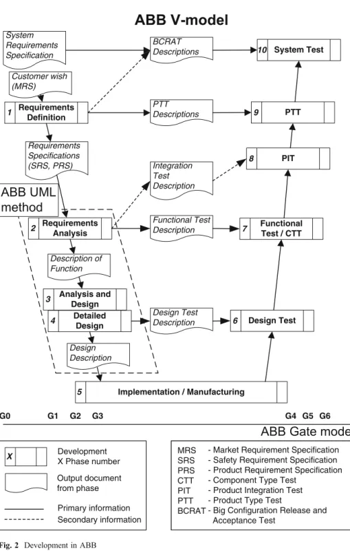
ABB has an existing methodological framework into which UML-based development was introduced. The overall ABB development method follows closely a traditional, and the method is used together with the ABB Gate model for projects, which defines the milestones for decision making in a project (ABB 2001). The goal of the ABB UML method is to cover the lower part of the V-model, from requirements analysis to functional testing. The first time the method was used, emphasis was mostly on analysis and design. The relations between the V-model, the Gate model and the ABB UML method are shown in Fig.2. G0...G6 refers to the gates of the Gate model and indicate when these are passed.
The ABB UML method was developed internally. It was not based on any particular method for UML-based development, but those responsible for it had experience with development based on UML, and were familiar with basic literature on such development, for example (Booch et al.1998; Douglass 2004; Fowler2003). The main reason why UML-based development was chosen as a basis for a semi-formal development method was the good tool support for modelling with UML. The ABB UML method is generic and thus had, at its inception, no particular relevance to the specifics of software development in ABB. The company’s plan was to start with a basic method and develop it in response to experience gained from the projects in which it is used.
Pri: 1 SIL 2 Stability: Stable Source: Technical Management Definition:
MEMORY INTEGRITY VERIFICATION
All volatile memory shall be tested cyclically to support the diagnostic coverage achieved with the used 1oo2 memory architecture.
Req. Type: Safety Function
Req. ID
SR-DGN-034
Motivation:
This is necessary in order to detect dormant failures also in unused areas of the memory. This is one of the necessary measures to enable use of (limited) dynamic memory allocation.
NOTE: With either “double memory” or “double and inverted” storage in single memory architectures, low effectiveness will be sufficient (stuck-at faults). In this case, the cycle-time requirement is based on EN 298, i.e. considered as a second fault that has to be detected within 24 hours.
Pri: 1 SIL ≤ ≤ ≤ 2 Stability: Stable Source: Product Management Definition:
ENHANCED CPU2R PROCESSOR MODULE
There shall be an enhanced CPU2R, PM865, processor module with necessary functionality for SIL 2 certification, available.
Req. Type: System Architecture, HW
Req. ID
PR-DLV-033
Motivation:
Market requirement to meet the requirements for SIL 2 with the safety controller. In addition, to reach a SIL 3 classification of the safety system when used together with the SM in a 1oo2 structure, this module must comply fully with the applicable requirements for SIL 2.
NOTE: This processor module shall be based on the PM864.
System Test 10 System Requirements Specification Implementation / Manufacturing 5 Design Test 6 Detailed Design 4 Integration Test Description Design Description Design Test Description BCRAT Descriptions PTT Descriptions Functional Test Description PTT 9 PIT 8 Functional Test / CTT 7 Analysis and Design 3 Requirements Analysis 2 Description of Function Requirements Definition 1 Customer wish (MRS) Requirements Specifications (SRS, PRS) Primary information Development X Phase number Output document from phase Secondary information
X - Market Requirement Specification- Safety Requirement Specification
- Product Requirement Specification - Component Type Test
- Product Integration Test - Product Type Test
- Big Configuration Release and Acceptance Test MRS SRS PRS CTT PIT PTT BCRAT G0 G1 G2 G3 G4 G5 G6
The ABB Gate Model stipulates that project documents should be reviewed at specific milestones in the project. As a consequence, the ABB UML method is document-driven. The development process is centred on two documents: thedescription of function(DOF), which describes the results of the requirements analysis, and thedesign description(DD). There were predefined templates for these documents. The UML models were inserted into these documents automatically, using Rational Rose and Rational SoDA.1The models are reviewed only as part of the documents.
The ABB UML method prescribes the use of use cases, sequence diagrams, deployment diagrams and class diagrams. The use of state chart diagrams and activity diagrams is optional. The method provides guidelines for the requirements analysis of both software and hardware, guidelines for the design of software, and guidelines for using Rational Rose. In addition, there are guidelines aimed specifically at satisfying the safety standard (Hansen and Gullesen2002). Iterations are encouraged within each phase, and the phases in the development project should, to some extent, be conducted in parallel; that is, the analysis phase does not need to be completed before starting on the design phase or on the imple-mentation. The ABB UML method (framed in Fig.2) was the subject of evaluation in this case study, not the complete V model. The steps of the ABB UML method are shown in AppendixA.
3 Research Method
The overall research method applied here is a case study (Yin2003). Case studies can be exploratory, descriptive or explanatory. This case study can best be characterized as exploratory due to the lack of previous case studies on UML-based development. Case studies are most suitable for investigating research questions of the typeswhat,howand why. In this study, we investigate howthe company’s development process was improved by adopting UML-based development,what particular difficulties were encountered with the use of UML and provide some explanations forwhythese difficulties occurred. 3.1 Data Collection
ABB wanted the opinions of the project members on the ABB UML method. Interviews were conducted with 16 people who had experience with the ABB UML method in the project. The authors selected the interviewees so that all the sites, subprojects and roles in the project were represented. Table1shows the distribution of the interviewees. Sub-project B was the only one involving hardware and software development and so we included interviewees concerned with both aspects of development. ABB did not have sufficiently detailed historical data from previous projects that could be used in the assessment of this project and to supplement the interviews.
All the developers interviewed had applied the ABB UML method. Two of the managers had also done some development and applied the method, while others had reviewed project documents that contained UML. Some of the interviewees had had positive experiences when applying UML in previous projects, but those projects were smaller than the project under study and did not have the same safety requirements. Most interviewees, however, had no particular expectations regarding the ABB UML method at the start of
the project, but applied it because they had to in order to satisfy the safety standard. The interviewees’experience in ABB varied from approximately two years to more than 25 years. The interview guide was developed by the authors. The interviews were semi-structured, based on the interview guide shown in Appendix B, but adapted to each interviewee. The aim was to encourage the interviewees to speak freely about the different aspects of the project and the ABB UML method. Each interview lasted from 30 to 50 min, and was conducted by two researchers not employed by ABB (the first and fourth authors). 3.2 The Analysis Procedure
The interviews were taped and transcribed before analysis. The interviewees had backgrounds that varied enormously. Consequently, not all of the questions in the interview guide were answered by all the interviewees. Some of the questions were open-ended and were answered differently by the different interviewees. It is, therefore, not feasible to report answers on the individual questions. Instead, the transcribed interviews were analyzed according to the principles of grounded theory (Strauss and Corbin1998), as well as on advice in the literature on the analysis of interviews (Eisenhardt1989; Seaman
1999). There is no standard way of analyzing in-depth interviews, and papers seldom describe in detail how such analysis is done (Huberman and Miles2002). Consequently, we had to identify for ourselves a suitable way of doing the analysis in this case. We decided to do it in the following steps:
1. Identify categories for coding
The categories are shown in Appendix C. There are categories for the following: interviewees’ expectations, experience and training, possible improvements, opinions about project characteristics, and difficulties related to the use of UML. The categories are based on the interview guide and on experience gained from the actual interviews. The categories related to improvements are based principally on the expectations that ABB had when the method was introduced, and the categories related to project characteristics are the results of project decisions that could cause problems.
2. Code the interviews
All the relevant sentences in the interviews were coded according to one or more categories. The interviewees often expressed themselves in many words, so some of the sentences from the interview were simplified to facilitate the rest of the analysis.
Table 1 Distribution of interviewees
Project\Site Norway Sweden site 1 Sweden site 2 Total
Sub-project A 2 developers 1 proj. manager
3 developers
6
Sub-project B 1 proj. manager s/w
1 developer s/w 1 proj. manager h/w 1 developer h/w
4
Sub-project C 1 proj. manager
1 developer
2
Overall project 1 manager
1 quality manager 1 system architect
1 quality manager 4
Several iterations of steps 1 and 2 were performed, in order to identify an appropriate set of categories.
3. Sort the sentences
All sentences related to possible improvements were sorted into descriptive (describing the area), positive (supporting an improvement) and negative (opposing an improve-ment). With respect to the sentences about difficulties with UML and problematic project challenges there were only sentences describing these as problematic.
4. Check background of interviewees
The varying backgrounds of the interviewees meant that not all of them had experience with each topic. Hence, for improvements within the specific topics, we examined who of the interviewees had experience that would enable them to have an opinion. For project characteristics, we examined who had found each characteristic to be problematic. 5. Identify relationships
Relationships were identified between project characteristics and difficulties related to the use of UML. A project characteristic was considered to be one cause of a UML problem if it was explicitly mentioned as such or the two were mentioned together in the interview in a way that strongly indicated a relationship.
4 Improvements in the Development Process
We have refined ABB’s expectations for improvement in the different areas:
A1: Traceability, defined as support for the construction of models that enables traceability from requirements to code.
A2: Communication, defined as ease of discussing design and implementation both within the development teams and in reviews.
A3: Design, defined as support for design activities as well as perceived structural properties of the code.
A4: Documentation, defined as documentation of code for the purpose of passing reviews (gates) as well as expected future maintainability.
A5: Testing, defined as ease of making functional test cases and their coverage. A6: Development costs.
The positive and negative sentences related to each of the areas were used to establish the extent to which there were improvements. Not all the interviewees mentioned potential improvements in all areas. There are several reasons for this. One interviewee was the manager for the whole safety project and did not have opinions on specific aspects of the development process, but had opinions on documentation and costs. For three of the interviewees, this was their first project in ABB. Hence, they did not have opinions on whether there were improvements. The only exception was with respect to documentation, because they had read the documentation of previous projects. In addition, one of the in-terviewees had not been involved in testing, two had not been deeply involved in development and had no opinions on design and traceability, and three had worked in small teams that had not been involved in reviews and could not have opinions about communication.
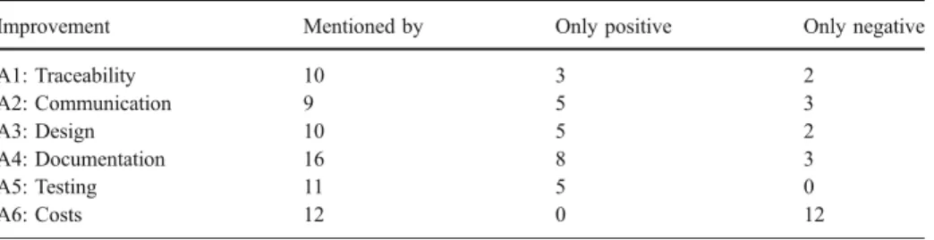
Table2shows the interviewees’opinions related to A5 about testing. Each row represents the opinion(s) of one interviewee. Five of the interviewees had only positive opinions, while six had both positive and negative opinions, although mostly positive. Table3 shows the
results of the coding of the interviews with respect to the different areas for improvement. The table shows how many of the interviewees mentioned each of the areas, how many had only positive opinions, and how many had only negative opinions. Most of the interviewees with both positive and negative opinions were, however, mostly positive as in the example in Table2. Table3shows improvements on all aspects except development costs, which were considered to have increased due to the introduction of UML-based development. The interviewees had, however, also experienced difficulties with all aspects. Below is a summary of how and the extent to which each aspect was improved.
TraceabilityThe method was considered to give good support for tracing from
require-ments to code and vice versa. This represented an improvement compared with the previous situation with only textual descriptions of analysis and design, and it helped ensure that all requirements were implemented. The interviewees had struggled somewhat with the tool to make it accept external references to the textual requirements. The large amount of legacy
Table 2 Opinions on testing
Positive Negative
The analysis and design models are input to testing and that works quite well, that is, it has led to a better focus on completeness.
The UML models are too large and detailed to be used effectively. It has been easy to make test cases, and the results of
the tests are good.
There were uncertainties about how to test and how to document the tests. The test cases were planned already during analysis.
We didn’t do that before.
Test cases were defined early and in a structured manner. This job, which would normally be big, took only one day. Testing has revealed higher quality in terms of fewer errors.*
We detect more errors now.*
It is much easier to write the functional test cases when we have use cases.
The use cases are often too detailed and then the test cases get too detailed as well.
We have used sequence diagrams in the testing. We
have detected errors that we wouldn’t have detected
otherwise.
The testers should now know how to write test specifications because they are based on UML.
I’m not certain that the testers always apply use cases and sequence diagrams in testing.
The use of UML has had a positive effect on the number of defects.*
The testers have not been trained in UML and consequently do not use the UML-diagrams as input as much as they should.
We use the UML models to generate test cases. It is now a lot easier than before to identify which test cases must be run after an update.
Working with UML in a structured manner provided a better basis for testing.
I don’t think that this has led to a large difference with respect to testing since we did not succeed very well in the earlier phases.
code, of which large parts were not reverse engineered, means that not all the code in the product can be traced back to the requirements.
Design of the code The use of the ABB UML method dictated a greater focus on design than
had been the case previously. The interviewees thought that people had come to realize the importance of designing before coding, which realization had resulted in an improved design. Previously, a prototype would often evolve into code, while now the development is more top–down, and a design framework is available before coding starts. In particular, the interviewees considered that the use of sequence diagrams forced them to design thoroughly. Some found, however, that there was not sufficient support in the method for combining top– down and bottom–up development, something which was necessary when many building blocks were already available in the form of hardware components or legacy code.
DocumentationThis project was better documented, both in terms of quantity and quality,
than previous software development projects in ABB. The documents now had a more unified structured with respect to content, and the interviewees found it easier to read them because of the common structure. The interviewees thought that more software developers can learn UML than learn to express themselves well in English. In addition, several of the interviewees emphasized that the developers found it more fun to make diagrams than to write textual documentation; hence, they produced more a comprehensive set of analysis and design documents. The interviewees found use cases and sequence diagrams to be particularly useful. They had, however, experienced difficulties with the format of the documents due to problems with the templates, such as which parts of the UML models were automatically inserted into the documents and the numbering of the sections in the documents. The documents were also often very large because the project members found it difficult to know how much context they should include in their models in order to describe their own part. Some documents, for example, contained several hundred pages describing only one piece of functionality. Some interviewees from projects A and B, the sub-projects which did not generate code from the UML models, thought that they spent too much effort on producing documentation during the project that would be outdated when the product was finished. Those who generated code automatically also reverse engineered their code to update their models and did not experience this problem.
Testing The development of test cases became quicker and easier when the UML models
were available, and the coverage of the test cases had improved. On the negative side, the large amount of detail in the UML models made them difficult to use as input to testing. Not all the testers had received training in UML, which meant that they could not easily apply the UML-based test cases, and consequently these were used less often in testing than they could have been.
Table 3 Results on possible improvements
Improvement Mentioned by Only positive Only negative
A1: Traceability 10 3 2 A2: Communication 9 5 3 A3: Design 10 5 2 A4: Documentation 16 8 3 A5: Testing 11 5 0 A6: Costs 12 0 12
Costs There were, of course, costs related to learning a new method. The introduction of a new method also led to much rework. For example, some of the interviewees rewrote the
description of functionseveral times, due to a revised understanding of the nature of use
cases. The amount of detail in the analysis models meant that these sometimes had to be updated later in the project. The interviewees had also expended a great deal of effort on discussing how to best apply UML, both within the teams and in the reviews. In addition, the reviews were considered to have taken more time because the documents were produced with a new method. The interviewees found it difficult to estimate how much the introduction of UML-based development had cost in terms of extra effort, but several of them guessed that it had doubled the effort on the project. The interviewees thought, however, that there might be improvements with respect to costs on future projects, when they could benefit from the documentation made on this project and the team members would be more experienced.
5 Challenges in the Project
The previous section showed that the interviewees had experienced several improvements to their development process as a consequence of introducing UML-based development, but also that difficulties with using UML, in combination with characteristics of the project that were the results of project management decisions, had caused difficulties and thus had reduced the possible positive effects of introducing such a development method. This section describes the difficulties experienced by the interviewees, the project characteristics that were considered to cause most problems and how these characteristics affected the use of UML.
5.1 Project Characteristics and their Consequences
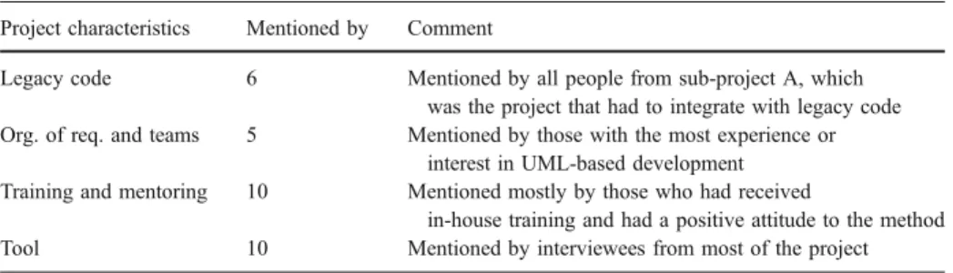
The interviewees mentioned four characteristics of the project that contributed to the difficulties with using UML and that had led to problems with obtaining the desired improvements. These characteristics were the consequences of project management decisions made because of budget and timing constraints in the project: (1) it was considered too costly to reverse engineer into UML the large amount of legacy code that the project had to modify and integrate with, (2) the requirements were distributed to the teams based on physical, and not functional, units of the system, (3) it was considered too costly to provide thorough training for all people involved in the project, (4) the choice of tools for the modelling process possessed functionality that was not in accordance with the needs of the project. Table 4shows how many of the interviewees described difficulties with the four project attributes. The table also describes the interviewees who mentioned the characteristics.
5.1.1 Legacy Code
Reverse engineering of the complete existing code base before the start of the project was considered too difficult, and consequently too expensive. The ABB UML method stipulates that the parts of the existing code that will integrate with the new code should be reverse engineered into UML models. It also stipulates that interfaces should be identified in these models and that modelling of the new system should use these interfaces, but there is little support on how to actually do this in the method. UML-based development methods mostly
assume development from scratch, and to the authors’ knowledge, there is little meth-odological support for using UML when modifying existing, non-object-oriented systems, even though it is often necessary and also recommended to introduce UML into an existing production environment (Selic2003). The interviewees described the problems related to the large amount of legacy code that was not reverse engineered, and the consequences of these problems. An example of statements about integration with, and modification of, legacy code is given in Table5. Each row relates the opinion of one interviewee.
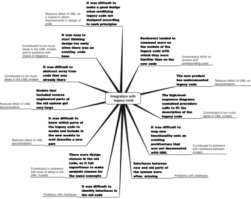
Figure3shows the interviewees’opinions about the consequences of having to deal with a large amount of legacy code. Each statement from the interviewees is categorized to clarify the relationships. The main consequences were the following:
& Difficulties with identifying which parts of the architecture implemented which parts of the functionality, and how the new requirements related to the existing functionality. This created difficulties when distributing requirements to teams.
Table 4 Opinions on aspects of the project
Project characteristics Mentioned by Comment
Legacy code 6 Mentioned by all people from sub-project A, which
was the project that had to integrate with legacy code
Org. of req. and teams 5 Mentioned by those with the most experience or
interest in UML-based development
Training and mentoring 10 Mentioned mostly by those who had received
in-house training and had a positive attitude to the method
Tool 10 Mentioned by interviewees from most of the project
Table 5 Statements related to having legacy code Statements
Those who had to integrate with legacy code had a much tougher job using this method than had those who developed from scratch, because we have not succeeded in reverse engineering all of the system; for example, not the parts that were very C-oriented. This means that we often did not have UML interfaces in the existing code, and it was necessary with so many adaptations in the code to integrate the new parts that we felt that we might as well document and test.
The person I worked with implemented new functionality in the existing code and met bigger problems than I, who developed from scratch, did. He had a new part, modelled in UML. To realize it, the old code had to be changed almost every second line. Then it was difficult to view the old system as a black box. We experienced problems because we added to functionality that was not functionally documented, and to
design properly, for example, using a state diagram, you need an existing design that builds on a state diagram. For the most part, the legacy code was not designed in such a way.
The main problem was having existing code that should be modified. It was necessary to know which parts of the old system should be included in the models in order to describe the new part correctly. I believe it would have been much easier if we had developed from scratch. Reverse engineering resulted in very large design documents where only a small part was useful when modelling the new functionality.
We added new functionality to an existing, complex software system that was badly documented. In addition, the templates and guidelines that we used were not adapted to integration with legacy code.
We modelled against a system that was not object-oriented. There were not, for example, always classes or interfaces in the old code that we could use, so we had to simulate that there were interfaces at the points where we needed them.
& Both developers and reviewers had difficulties with abstracting away from the code in analysis and design when they knew the existing code well. This contributed to analysis and design models with too much detail.
& Difficulties with identifying clear-cut interfaces to the old code that could be used in the new models. It was necessary to know the old code well in order to know how much of it had to be modelled to document the new part well.
& General problems with obtaining benefits with respect to design when applying UML because they had to know, and adapt to, the existing code.
5.1.2 Organization of Requirements and Teams
The distribution of requirements to teams was mostly done before beginning to use the ABB UML method. It was done based on physical units, previous experience and on which teams had available resources. There were approximately 1,000 requirements for the new system, but these were not organized hierarchically. The ABB UML method states that identical functionality should be identified and separated out as included use cases, but there was no organized activity of identifying similar functionality over several teams; nor was there any activity on integrating the different models and ensuring unified interfaces. Figure4shows the interviewees’opinions about the consequences of not orga-nizing and distributing requirements to teams based on functionality and not orgaorga-nizing
Integration with legacy code
Reviewers tended to Reviewers tended to Reviewers tended to Reviewers tended to comment more on comment more on comment more on comment more on the models of the the models of the the models of the the models of the legacy code with legacy code with legacy code with legacy code with which they were which they were which they were which they were familiar than on the familiar than on the familiar than on the familiar than on the new code new codenew code new code
Unneccesary effort on reviews and corresponding costs
The new product The new product The new product The new product has undocumented has undocumented has undocumented has undocumented legacy code legacy codelegacy code legacy code
Reduces effect of UML on documentation The high-level The high-level The high-level The high-level sequence diagrams sequence diagrams sequence diagrams sequence diagrams contained procedure contained procedure contained procedure contained procedure calls to fit the calls to fit the calls to fit the calls to fit the description of the description of the description of the description of the legacy code legacy code legacy code legacy code
Contributed to too much detail in UML models
It was difficult to It was difficult to It was difficult to It was difficult to map new map new map new map new functionality onto an functionality onto an functionality onto an functionality onto an existing existing existing existing architecture that architecture that architecture that architecture that was not documented was not documented was not documented was not documented with UML with UML with UML with UML
Contributed to problems with interfaces between models
Interfaces between Interfaces between Interfaces between Interfaces between new and old parts of new and old parts of new and old parts of new and old parts of the system were the system were the system were the system were often missing often missing often missing
often missing Problems with interfaces
It was difficult to It was difficult to It was difficult to It was difficult to identify interfaces in identify interfaces in identify interfaces in identify interfaces in the old code the old codethe old code the old code Problems with interfaces
There were design There were design There were design There were design classes in the old classes in the old classes in the old classes in the old code, so it felt code, so it felt code, so it felt code, so it felt superfluous to make superfluous to make superfluous to make superfluous to make analysis classes for analysis classes for analysis classes for analysis classes for the same concepts the same concepts the same concepts the same concepts Contributed to problems
with level of detail in the UML models
It was difficult to It was difficult to It was difficult to It was difficult to know which parts of know which parts of know which parts of know which parts of the legacy code to the legacy code to the legacy code to the legacy code to model and include in model and include in model and include in model and include in the new models to the new models to the new models to the new models to well describe a new well describe a new well describe a new well describe a new part
partpart part Reduces effect of UML documentation
Models that Models that Models that Models that included reverse included reverse included reverse included reverse engineered parts of engineered parts of engineered parts of engineered parts of the old system got the old system got the old system got the old system got very large very largevery large very large Reduces effect of UML documentation
It was difficult to It was difficult to It was difficult to It was difficult to abstract away from abstract away from abstract away from abstract away from code that was code that was code that was code that was already there already there already there already there Contributed to too much
detail in the UML models
It was easy to It was easy to It was easy to It was easy to start thinking start thinking start thinking start thinking design too early design too early design too early design too early when there was an when there was an when there was an when there was an existing code existing code existing code existing code base basebase base Contributed to too much detail in the UML models and to problems with choice of diagrams
It was difficult to It was difficult to It was difficult to It was difficult to make a good design make a good design make a good design make a good design when modifying when modifying when modifying when modifying legacy code not legacy code not legacy code not legacy code not designed according designed according designed according designed according to such principles to such principles to such principles to such principles Reduces effect of UML as
a means to obtain improvements in design of code
cooperation among teams that were developing functionality that interacted with the functionality being developed by other teams. The main consequences were the following:
& The focus was often on physical components as such and not on functionality.
& Related functionality was not always distributed to the same team, meaning that it was often difficult to map requirements to use cases.
& One analysis model did not necessarily correspond to a logical part of the system. Hence, it was difficult to integrate different models, and in some cases there was overlapping functionality in different models.
5.1.3 Training and Mentoring
Most of the developers were novices at modelling with UML when starting to work on this project. Otherwise, they were well-qualified developers (most holding the equivalent of an MSc degree) and with several years experience at ABB. They were familiar with both the V-model and Gate model. At the start of the project, they attended courses of two to five days that covered UML syntax, Rational Rose tools and the ABB UML method. A special team, the UML team, was set up to help the rest of the project with the use of UML, which included responsibility for developing templates and for reviewing documents, with particular focus on the correct use of UML. The number of people in the UML team varied from three to five over the course of the project.
The interviewees reported that there had been too little training because managers, reviewers and testers, who did not themselves develop, did not receive training even though they had to read and understand the models. Some of them also had roles that required them to motivate and teach others to use UML correctly. Developers who started on the project after the courses did not receive the same training as the others.
There were also problems reported with the training they received. The interviewees said that the courses focused too much on UML syntax and too little on the ABB UML method and semantics of diagrams and constructs. There were not enough practical exercises on using the tools and it was not made clear what should actually be achieved by modelling. It was considered necessary, but not sufficient, to master the syntax in
Distribution of requirements to teams
Badly structured models, in particular use case models
Reduces effect of UML documentation
Individual models that were difficult to integrate
Contributed to problems with interfaces
Difficulties with getting a complete overview of (parts of) the system
Reduces effect of UML documentation
Difficulties with the relationship between requirements and use cases
Contributed to some problems with traceability
Focus on realizing complete components too early when focus should be on functionality
Contributed to problems with level of detail It was difficult to
know which other teams to integrate with
Contributed to problems with interfaces
It was often difficult to see where each use case fits in Reduces effect of UML
documentation It was difficult to understand and realize requirements in isolation Contributed to additional costs Overlapping functionality in different analysis models Reduces effects of UML as a means to improve design of code
Analysis models that did not correspond to a logical part of the system Reduces effect of UML documentation
order to apply UML successfully. The courses were developed for the project, but not adapted to the specific context.
The interviewees believed that the UML team was not sufficiently qualified, and did not have sufficient authority, to guide the total use of UML in the project because they lacked the necessary experience with both development and UML. At the beginning of the project there were some senior developers in the team, but these were considered too important for the rest of the project to be given time to spend on the UML team. The members of the UML team did not receive additional training in UML-based development.
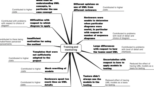
Figure5shows the interviewees’opinions on the consequences of these problems. The main consequences were these:
& It was not well understood how to apply the concepts of actors and use cases in the context of embedded development.
& There were large differences in how the different teams applied UML and the
method.
& Those who had attended courses often expected to be able to use the course material directly in the development, but this caused difficulties since the material was not adapted to the project context.
& The templates that were used in the project were not sufficiently adapted to the project context.
& The project members did not always use UML-models when they could have used
them. UML-models were, for example, not always applied as input to making test cases.
5.1.4 Tools Used in Modelling and Documenting
Some of the interviewees believed that Rational Rose lacked stability, but they were mostly satisfied with its functionality. Rational Rose SoDA was used to produce documents
Training and mentoring
Different opinions on Different opinions on Different opinions on Different opinions on use of UML from use of UML from use of UML from use of UML from different reviewers different reviewersdifferent reviewers different reviewers Contributed to higher costs Reviewers were Reviewers were Reviewers were Reviewers were unable to determine unable to determine unable to determine unable to determine when particular when particular when particular when particular diagrams were diagrams were diagrams were diagrams were useful, in particular useful, in particular useful, in particular useful, in particular with respect to with respect to with respect to with respect to number of sequence number of sequence number of sequence number of sequence diagrams diagrams diagrams diagrams Contributed to problems with level of detail and choice of diagram
Large differences Large differences Large differences Large differences with respect to how with respect to how with respect to how with respect to how the teams used UML the teams used UML the teams used UML the teams used UML
Contributed to problems with level of detail and interfaces
Uncertainties with Uncertainties with Uncertainties with Uncertainties with respect to how to respect to how to respect to how to respect to how to apply models in apply models in apply models in apply models in testing testingtesting testing
Reduced the effect of having UML models as a basis for testing
Testers didn't Testers didn't Testers didn't Testers didn't always use the always use the always use the always use the models in the models in the models in the models in the testing testing testing testing
Reduced effect of having UML models as a basis for testing Reviewers spent too
Reviewers spent too Reviewers spent too Reviewers spent too much time on UML much time on UML much time on UML much time on UML details details details details Contributed to higher costs Much rewriting of Much rewriting of Much rewriting of Much rewriting of models modelsmodels models Contributed to higher costs
Templates that were Templates that were Templates that were Templates that were not sufficiently not sufficiently not sufficiently not sufficiently adapted to the adapted to the adapted to the adapted to the project projectproject project Contributed to higher costs Insufficient Insufficient Insufficient Insufficient motivation for using motivation for using motivation for using motivation for using the method the method the method the method Contributed to there being
smaller/fewer perceived improvements Difficulties with Difficulties with Difficulties with Difficulties with respect to which respect to which respect to which respect to which diagram to apply diagram to apply diagram to apply diagram to apply Contributed with problems
with respect to choice of diagram Much time on Much time on Much time on Much time on understanding UML understanding UML understanding UML understanding UML concepts, in concepts, in concepts, in concepts, in particular the use particular the use particular the use particular the use case concept case concept case concept case concept Contributed to higher costs
automatically from the models in Rational Rose; that is, the models were inserted into predefined Word-templates. The interviewees reported that it was difficult to create documents with an acceptable layout when the models were inserted into documents automatically. For example, the developers were unable to set the text fonts in the UML-models in Rational Rose, and they did not succeed in controlling the numbering of the sections in the documents. Therefore, they had to make quite a lot of changes to the automatically generated documents, and consequently it was costly to make changes in the models because this implied generating new documents.
In addition, the interviewees thought that Rational Rose may also have contributed somewhat to the low level of detail in the high-level sequence diagrams because Rational Rose facilitates in the sequence diagrams, the use of classes and methods that have already been defined in class diagrams.
5.2 Difficulties with Using UML
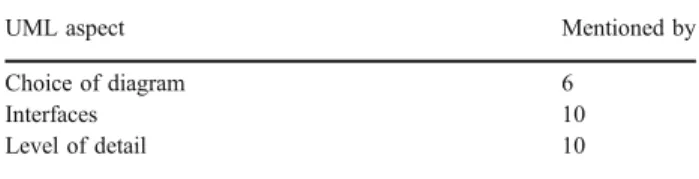
The previous section described project decisions that caused problems with applying UML and thus reduced the effect of introducing UML-based development. The inter-viewees mentioned three main difficulties with applying UML: (1) the choice of diagram to use in a specific situation, (2) the interfaces between models, and (3) the level of detail in the models. Table6shows how many of the interviewees mentioned problems with each of the aspects.
5.2.1 Choice of Diagrams
Some interviewees reported problems with the choice of diagram to apply. They found that there was too much focus on use cases and sequence diagrams in the ABB UML method, and thought that activity diagrams could be more useful early in analysis when few actual objects have been identified. More use of activity diagrams could have contributed to deterring the focus on detailed classes. The interviewees had, however, focused on making the UML models that were compulsory in the ABB UML method, since they did not feel that they had a good enough grasp of the goal of applying each of the models to choose when to apply which. The lack of insight into exactly what each model should express also meant that the interviewees found it difficult to know when it was necessary to supplement the models with text and when the models were self-contained.
5.2.2 Interfaces
The interviewees had experienced large problems with interfaces between models describing different, but interacting, parts of the system. Well-described interfaces were
Table 6 Results on difficulties
with UML UML aspect Mentioned by
Choice of diagram 6
Interfaces 10
considered vital for understanding where each part fits in and to get an overview of the system, but most of the interviewees found that the interfaces were either missing or too detailed.
High-level interfaces were in the form of actors. In addition to actors that were external to the whole system, such as operators and hardware devices, the ABB UML stipulates that subsystems should be considered as actors for each other. These subsystems could be legacy code or other subsystems being developed in parallel. An actor mostly interacts with a subsystem in several places. In the modelling process, such low-level interfaces were marked with the symbol ○. Such interfaces were gradually substituted with actual function calls when these were established. The interviewees had experienced several problems:
& For interfaces in the form ofactors that were not human usersit was more difficult to identify them and how they would interact with the system than for those actors that represented human users.
& Interfaces in the legacy code posed difficulties because the legacy code was only partially reverse engineered into UML models. Consequently, there were often few interfaces in the old code that could be used directly.
& Interfaces in subsystems that were developed in parallel also posed problems. The ABB UML method stipulates that the people responsible for the different subsystems should communicate about the exact nature of the interface. However, this was often difficult because the different subsystems were developed according to different schedules and some subsystems were developed mostly bottom–up, based on existing components, while others were developed top–down. The interviewees also reported that they did not have a good grasp of how to group use cases into subsystems, something that also contributed to the interfaces between the subsystems not being clear-cut.
5.2.3 Level of Detail
Examples of statements about level of detail in the models are given in Table7. Each row relates the opinion of one interviewee. The main problems were these:
& The teams had started to think about code when the focus should have been on
functionality. Both the use cases and the high-level sequence diagrams were considered to be too detailed, because they often included the same functions as the code.
& It was difficult to decide how to divide functionality into use cases and to decide how many sequence diagrams should be made for each use case.
& The distinction between analysis and design was not clear. The analysis models
included design details and were consequently often difficult to use in the design, because they constrained the design models.
6 Scope and Validity of the Results
6.1 Scope of the Results
In the authors’opinion, most of the experiences gained from this project are relevant for other large projects that introduce UML-based development. There are, however, a number of aspects particular to this project.
& Much of the software to be developed was real-time and embedded. The ABB UML
method was not particularly tailored to this kind of development. Only one of the interviewees stated, however, that he missed particular real-time features. Object-oriented modelling and UML-based development may be less suited for development of embedded software because the concepts of actors and use cases are more difficult to apply to a system where there is not so much external communication and because many of the objects are established in advance.
& The ABB UML method was applied within an overall development process with
focus on the acceptance of project documents at predefined gates in the development project. This meant that the documents with the UML models, and not the models themselves, were subject to review. Many of the interviewees had experienced
Table 7 Problems related to level of detail in the UML models Problems
The embedded software interfaces hardware devices. Hardware developers are used to starting by specifying a number of registers that bits will be flipped in and out of. They do not think in terms of functionality to request or provide. This attitude leads to models that are too detailed; for example, high-level sequence diagrams showing actual function calls, and design models that were too large and complex and thus difficult to use.
It was difficult to decide on the level of detail for the use cases. For example, do we need two or 20 use cases to describe the problem? We found out that it was easier to pass reviews with fewer use cases.
It was difficult to understand the use case concept and to describe the correct use cases. We ended up with too much design in our use cases and our high-level sequence diagrams. This was, to a great extent, because we were describing a physical component of the system and found it difficult to start at a high level of abstraction. The difference between analysis and design was not clear.
Use cases can be described in a number of different ways, all of which are correct. In practice the
development, and consequently the descriptions of the models, are always a mixture of top–down and
bottom–up; that is, between describing functionality and considering the components of which a system
will consist.
There were large differences between the level of detail of the use cases of the different teams. Some made only one large use case for a large function that could have been split up, while others made a large amount of use cases and a complex use case model for functions that were quite simple.
We made more sequence diagrams than we actually needed in the analysis because the reviewers intended there to be a sequence diagram for each use case flow, regardless of how well that flow was described in the
use case. The reviewers were unable to see when a sequence diagram would be useful and when it wouldn’t.
We thought about code when we were supposed to focus on functionality. I think we should have made more effort to stay at a higher level of abstraction.
We had large difficulties with our high-level classes. Since we already had implementation classes in the legacy code, we thought it quite was useless to have to invent some high-level classes.
Our UML models were often too detailed. During design we were constrained by our use cases and high-level sequence diagrams, since these were so detailed and included design.
The design models have become very detailed. There is too much information in them and they are up to three hundred pages long.
difficulties with the format of these documents, and that may have overshadowed their opinions on UML-based development as such.
& The requirements were well-defined before the application of the ABB UML method. The safety requirements were derived from IEC 61508. Most of the functional requirements were the result of the system’s relations to hardware artifacts, while some of them were responses to the needs of users of the system, such as process operators and engineers. This meant that the functional requirements were mostly independent of users’ needs and abilities to define requirements. Use cases are claimed to be particularly useful for eliciting and elaborating functional requirements, but such activities were not part of this project, and use case modelling may, therefore, have been considered less useful than it would have been if such activities had been included.
& The use cases were constructed solely by developers who were also domain experts. ABB develops products for sale, and consequently there were no clients involved in the development process. This probably contributed to the low level of detail in the use case models.
& The teams had worked in a very vertical way, mostly with one team being
responsible for analysis, design and coding. The benefits of analysis and design with UML may have been greater if the analysis and/or design models had been handed over to other teams for further elaboration. In addition, in practice, not all steps of the ABB UML method were necessarily followed by all teams. Absolute conformance to a development method is, however, seldom observed in software development projects (Fitzgerald 1997), and in this case the safety constraints forced the developers to produce all the UML-models stipulated by the ABB UML method. ABB chose UML-based development because of good tool support. We believe that the project would have experienced many of the same improvements and challenges if they had chosen another modelling language and method as a basis for their improvement initiative. However, we do believe that there are some matters that are particular to UML-based development. The use of use case diagrams may lead to a focus on the overall system rather than on the individual parts. The packages in Rational Rose may also have contributed to an awareness of each team working on a part of a larger system. In this case, the system to be constructed was too large and complex to easily provide an overall picture of its functionality. Many of the difficulties reported in the interviews were related to problems with describing models and their interfaces in such a way that they could provide an overview of the system. These difficulties may have been lessened if a method for analysis and design had been used that had less focus on overall functionality and more on detailed design.
6.2 Validity of the Results
The results of this study are based on interviews with the project participants, and our measures are their perceived improvements and problems. The interviewees were selected to represent different parts of the project and they all had experience with using UML on the project. The people present at the interviews (the first and fourth author) were not employed by ABB, and the interviewees were guaranteed anonymity. Our impression is that the interviewees spoke freely. The conduct of interviews and confidentiality issues are discussed further in Hove and Anda (2005) which is, among others, based on the experiences from these interviews.
With respect to validity of results based on interviews there are, in particular, two aspects of validity to consider (Maxwell1992):
& Descriptive validity; that is, whether the interviewees’opinions are rendered correctly. In this case, the interviews were transcribed, based on tapes, by the research assistant who had been present at, but not directly involved in, the interviewing. The analysis was based on these transcribes.
& Interpretive validity; that is, whether the interviews are correctly interpreted. In this case, the interviewees spoke very informally, and ten of the interviewees were Swedish. Consequently, it was necessary to translate and rewrite the transcriptions somewhat before the coding of the interviews. It is possible that the meaning of some individual sentences may have been altered slightly in this process. The categories used in the analysis are the result of several iterations on coding the interviews, and previous iterations also included other categories for coding that were discarded because very few sentences in the interviews were coded according to them. These categories were requirements analysis, the method description and the syntax of UML in relation to improvements, project decisions and difficulties with UML, respectively. Three project members, who had not been interviewed, also read through and verified a draft of this paper.
There are few empirical studies on UML-based development with which to compare our results. Nevertheless, some of our results are supported by the results reported in a paper with lessons learned from developing embedded software (Pettit2004). That paper also reports improved communication due to the introduction of UML-based development, as well as challenges with respect to describing interfaces between UML models. Our results are also supported by the results from a study on the introduction of object-oriented development (Malan et al. 1995). The experiences reported in that paper also emphasize the need for sufficient training, reverse engineering of legacy code, and adequate distribution of subsystems to teams, as well as the economic challenges involved in these activities. Furthermore, some of our results are supported by the results from a study on the usability of UML diagrams (Agarwal and Sinha 2003). That study also revealed difficulties with understanding the concept of use cases and describing them with appropriate detail, as well as with modelling interface objects in class diagrams. Difficulties with level of detail in use case models have been mentioned, for example in (Armour and Miller2000; Cockburn2000; Kulak and Guiney2000).
7 Conclusions and Future Work
This paper reports the results of a case study on adopting UML and an associated UML-based development method in a large, international development project in ABB. Data was collected through interviews with 16 developers and managers. Principles from grounded theory were used in the analysis of the interviews.
The interviewees had obtained several immediate improvements as a consequence of introducing a UML-based development method. These were improved traceability of requirements to code, improved communication within the development teams (and to some extent in the reviews), improved design of the code, quicker development of test cases and better coverage of these, and a product that was better documented than were previous products. The interviewees also stated that there had been difficulties related to
obtaining these improvements and also that development costs had increased due to the adoption of UML. When applying UML, the interviewees had experienced difficulties with choosing an appropriate diagram in a specific situation, interfaces between different models, and with the level of detail in the models. There were four decisions made at the start of the project that the interviewees identified as having caused problems with the use of UML. These were related to lack of reverse engineering of legacy code, un-systematic distribution of requirements to teams, insufficient training and mentoring, and choice of modelling tools.
Despite the widespread use of UML in industry, there has been little evaluation of UML-based development in industrial projects. In the authors’opinion, this study thus represents a contribution to the body of knowledge regarding benefits and challenges involved in adopting UML-based development that should provide valuable input to the development of a theory in the field as well as to practitioners. The ABB UML method has also been changed, partly based on the results from this study.
The following activities are in progress, or are planned, in order to further evaluate the use of UML-based development in ABB. First, a questionnaire, with questions based on the results of the interviews, has been distributed to the participants in the project to investigate specific aspects of the development process in more detail. Second, project documents from the project, in the form of UML-documents, review reports and test reports are being analyzed, to identify what changes were made to the analysis models and what caused these changes to be made. Third, more case studies on the adoption, adaptation and use of UML-based development in various types of projects are needed to better understand how such development should be applied to improve software development processes.
Acknowledgments We acknowledge all the employees of ABB in Sweden and Norway who participated in the interviews and their managers. We thank Lionel Briand for valuable comments on the case study, and we also thank Hans Christian Benestad, Vigdis By, Dag Sjøberg, Marek Vokác, Ray Welland, Chris Wright and the anonymous reviewers for their comments on a previous version of the paper. The reported work was funded by The Research Council of Norway through the industry project SPIKE (Software Process Improvement based on Knowledge and Experience).
Appendix A. Brief Description of the ABB UML Method
The requirements analysis phase of the ABB UML method: R1. Identify actors and use cases, and document them
Actorsare the system’s external interfaces. Humans, timers, sensors, or anything else
that interacts with the system, can be an actor. For a use case diagram in a subsystem, other (interacting) subsystems should also be defined as actors.
Use cases:
& Define the system as seen from the actors’point of view.
& Represent the different usage of the system and system services.
& Capture the requirements.