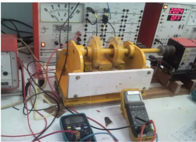
A New Design of Permanent Magnets Reluctance Generator Andi Pawawoi, Syafii
Full text
Figure


Related documents
It has always been a personal goal to continue my education and to return to school to complete the Bachelor’s portion of my nursing degree.. I am also pursuing re-entering the
A method of bonding together a refractory metal part and a Pt group metal part by applying to one surface of one of the parts a barrier layer composed of a mixture of
However, no studies have examined the impact of a lifestyle intervention including both diet- ary and physical activity components on epigenome- wide patterns of DNA methylation
JC-1 staining showed lower mitochondrial membrane poteintial as signified by increase in its monomers and decrease in aggregates in Mortaparib-treated HeLa cells (Scale bar = 20 μ
128-bit key (K2) will be used to encrypt the text file. In the proposed algorithm ADD* means addition modulo 2 16 and MULTIPLY* means multiplication modulo 2 16..
Our choice for this model is to showcase its efficiency in varying wind conditions as compared to the traditional horizontal axis wind turbine and contribute to
When selection is relatively weak, the pattern of imprinting that permits a greater rate of genetic response to selection depends on the frequency of the favored allele: the
Modular cascaded H-bridge multilevel inverters for single and three-phase grid connected PV systems are appeared in Fig.. 1.Each phase comprises of n H-bridge


