Christopher M. Gifford, Eric L. Akers, Richard S. Stansbury, and Arvin Agah
AbstractMobile robots are becoming more heavily used in environments where hu-man involvement is limited, impossible, or dangerous. These robots perform some of the more dangerous and laborious human tasks on Earth and throughout the solar system, many times with greater efficiency and accuracy, saving both time and re-sources. As we explore further away from Earth, higher levels of autonomy are also becoming more desired in such applications, one of them being remote sensing. This chapter covers mobile robots that have been designed and built at the University of Kansas to facilitate seismic and radar remote sensing of ice sheets in polar regions. These robots have been developed for and deployed in unstructured, polar environ-ments. System designs, components, deployment and data acquisition algorithms, and experimental results are discussed. In this chapter, future applications, such as an autonomous multi-robot seismic surveying surveying team, are simulated. Future planetary missions will hopefully incorporate similar robotic systems to conduct in-situ experiments on other planets.
Christopher M. Gifford
Electrical Engineering and Computer Science Department, University of Kansas, Lawrence, KS 66045, e-mail:[email protected]
Eric L. Akers
Mathematics and Computer Science Department, Elizabeth City State University, Elizabeth City, NC 27909, e-mail:[email protected]
Richard S. Stansbury
Department of Computer and Software Engineering, Embry-Riddle Aeronautical University, Day-tona Beach, FL 32114, e-mail:[email protected]
Arvin Agah
Electrical Engineering and Computer Science Department, University of Kansas, Lawrence, KS 66045, e-mail:[email protected]
1 Introduction
At the University of Kansas, the Center for Remote Sensing of Ice Sheets (CReSIS) [10] performs polar research to gather data and model ice sheets to better under-stand climate change and its effects on sea level rise. We have designed, built, and deployed mobile robots to autonomously traverse polar terrain and support experi-ments in Greenland and Antarctica. The problem we are faced with is to facilitate the use, and increase the efficiency of seismic and radar data acquisition in these types of environments. Integration of autonomy and mobility into remote sensing methods can potentially improve and enhance the process.
One of the sensors used to perform this research is a seismic sensor, or geo-phone. These highly sensitive geophones detect vibrations in the ground which can be recorded as images. These images, for example, can show characteristics of the subsurface, detect cracking (fault) locations, as well as provide information on what is beneath the ice sheets. CReSIS has also developed ground and ice penetrating radars that can also provide highly detailed images of the subsurface. We have used these radars to identify layers and areas of potential water within Earth’s ice sheets, as well as the extent of water presence at the interface between the ice sheet and the underlying bedrock. Together, these remote sensing techniques allow us to study and further understand how polar regions are changing in response to climate change.
Research in the field of robotics has been focusing on accurate sensing and au-tonomy, mostly performed in structured environments such as factories and homes. Robotic applications involving remote sensing and in-situ experiments in unstruc-tured environments have, however, been limited. Not only are navigation and actua-tion in such environments difficult problems, autonomy in hazardous environments represent larger challenges [34].
Another important aspect of integrating robotics and remote sensing surveys is that it limits human involvement, the most dangerous and costly portion of a sur-vey. The accuracy and quality of acquired data can also be potentially increased. For polar and planetary environments, this becomes extremely important for safety, reliability, and resource consumption. Furthermore, robotics increases precision and introduces repeatability into an otherwise time-consuming and complex human task. In particular, because seismic deployment is labor-intensive, expensive in terms of time and cost, and possibly dangerous, autonomously performing such tasks using mobile robots can be highly beneficial. Therefore, the goal is to combine robotics research with remote sensing systems to autonomously image the subsurface for polar and planetary applications.
As we explore further away from Earth, a need for a coupled increase in intelli-gence and autonomy arises as a result of large communication delays between robots and their remote human operators. During communication delays, robots could nav-igate to new locations, perform experiments, or build a map of an unexplored region of the surface. Other planets and their moons offer various unique and challenging environments for ground-based robots, ranging from the extreme heat and pressure on the surface of Venus to the icy landscape of Jupiter’s moon Europa. Future mis-sions to icy moon Europa may one day include a multi-robot seismic mission to
learn more about its subsurface and the ever-present search for Earth-like processes and life in the solar system.
This chapter covers mobile robots that have been designed at the University of Kansas to facilitate seismic and radar remote sensing in polar regions. Section 2 introduces two polar mobile robots, challenges and survivability issues, and their field operations in Greenland and Antarctica. Section 3 discusses designs and sim-ulations of single- and multi-robot approaches to automated seismic surveying. Fi-nally, Section 4 discusses the conclusions and future directions of work related to these systems.
2 Polar Mobile Robots
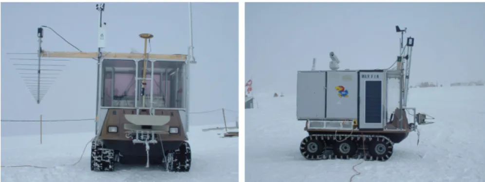
At the University of Kansas, mobile robots have been utilized to autonomously sup-port the Center for Remote Sensing of Ice Sheets (CReSIS) [10] and Polar Radar for Ice Sheet Measurements (PRISM) [23] projects. Mobile robots are required to transport a radar system across the ice sheet, following a precise movement pat-tern and tow an antenna, while ensuring the safety of the radar system. Mobile robots designed for harsh environments such as the polar regions can increase the efficiency of data collection in field experiments, reduce the potential dangers to humans, and enable experiments beyond the regular field seasons. When the data collection process requires several days, weeks, or months, special considerations must be made for the survivability of these robots. Two mobile robots, shown in Fig-ure 1, have been evaluated in Greenland and Antarctica during three field seasons for autonomous data acquisition using radar remote sensing. The following sections discuss challenges and survivability issues associated with polar robotics, platform components, sensing, and field operations.
Fig. 1 MARVIN I (left, in Greenland) and MARVIN II (right, in Antarctica) equipped with com-ponents for polar operations.
2.1 Challenges and Survivability Issues for Polar Robotics
There are many challenges faced by polar robots, as described in detail in [4]. Po-lar robots must operate in extremely cold temperatures. The temperatures at the Amundsen-Scott South Pole Base have been recorded to vary from -13.6oCelsius to -82.8oCelsius [26]. To address short-term survival during polar Summer seasons, onboard robot components must at least meet a minimum operating temperature of -40oCelsius. High wind speeds also produce many unique challenges to polar sur-vival. All components of the mobile robot must be ruggedized to handle high wind speeds. At the South Pole Station, the average wind speed is 5.5 meters per second with a maximum recorded gust of 24 meters per second [26]. Polar winds erode the ice sheet creating surface obstacles such as snow drifts and sastrugis. The blowing snow further contributes to low visibility.
Obstacles such as sastrugis can cause damage to the mobile robot. Sastrugis are dune-like ice structures that result from erosion of the ice sheet’s surface and may have only one steep side. Due to their unique shape, blowing snow, a lack of surface contrast, and inadequacies of stereo vision, sastrugis are difficult to detect. A robot cannot remain stationary for an extended period of time without snow drifting along one side. If a robot must suspend operation temporarily during a snow storm (i.e., lack of solar energy), it must maneuver such that it will not become stuck.
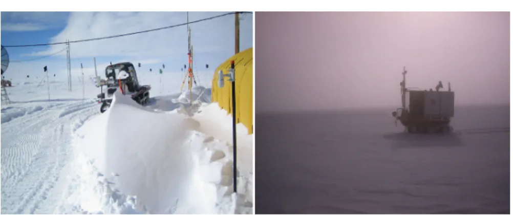
Any venture away from an established camp poses the risk of encountering a crevasse. Crevasses may be hidden by a layer, or “canopy”, of snow. To date, air-borne radar has been the most used mechanism for locating crevasses within an area, but that may be insufficient for long distance traversals. Researchers have utilized ground penetrating radar mounted on a boom several meters ahead of the vehicle to detect crevasses, which requires that the vehicle travels quite slowly [6]. Smaller robots may not be capable of supporting such a configuration because of the mass required to support the antenna boom. Additionally, vision sensors are often insuffi-cient for operation within polar environments. Blowing snow may obscure cameras, sonar, and laser measurement sensors. Depth perception is also limited when all backgrounds are white. Cloudy days may reduce visibility due to a lack of contrast. Currently, only millimeter-wave radar is capable of operating in these low visibility situations, but those are often heavy, consume power resources, and could be in-feasible in terms of cost. Figure 2 presents examples of limited visibility and snow drifting that was formed overnight in the polar regions.
2.2 MARVIN I
The first mobile robot for the PRISM project, MARVIN I, was constructed using a MaxATV Buffalo [29] All Terrain Vehicle (ATV) as the mobile platform. This sec-tion presents a descripsec-tion of the robot, and more thorough descripsec-tions are available in [3, 19]. The six-wheeled MaxATV, shown in Figure 3, features a skid-steering drive system. The robot has a ground clearance of about 12.5 cm. It can tow up
Fig. 2 A snow drift that formed overnight behind MARVIN II while in camp (left), and limited visibility due to blowing snow (right).
to 454 kg and haul 408 kg. A custom enclosure, shown in Figure 1, was built on top of the rover to house the robot’s sensors, actuators, computers, and all the radar equipment. A gas generator provides power to the onboard systems.
Fig. 3 Original Buffalo Max ATV used as the base platform for the MARVIN I mobile robot.
Linear actuators are used to automate the platform. The left and right brakes are controlled using linear actuators attached to the respective control handle for each. The engine’s throttle is controlled using a linear actuator, attached to the rover’s throttle control cable. The actuators are magnetically driven and provide 5 mm posi-tion accuracy. Localizaposi-tion was handled using a Topcon real-time kinematic (RTK) GPS [36] for centimeter-level accuracy (required for radar measurements), along with a gyroscope and inclinometer to provide the robot’s orientation. A compass can not be used in polar robots due to the skew caused by the close proximity to the magnetic poles. A laser range-finder is used to detect obstacles. An internal temperature sensor provides feedback regarding the current temperature within the environmental enclosure. Lastly, a weather station and a pan-tilt-zoom camera are
included for outreach activities of the project. Figure 4 presents MARVIN I and its components in Greenland (2004), and also shows the mounting of a radar antenna on the platform. Automated navigation is handled using a ruggedized laptop.
Fig. 4 MARVIN I in Greenland (2004) with external sensor components. A radar antenna mounted for data acquisition is also shown.
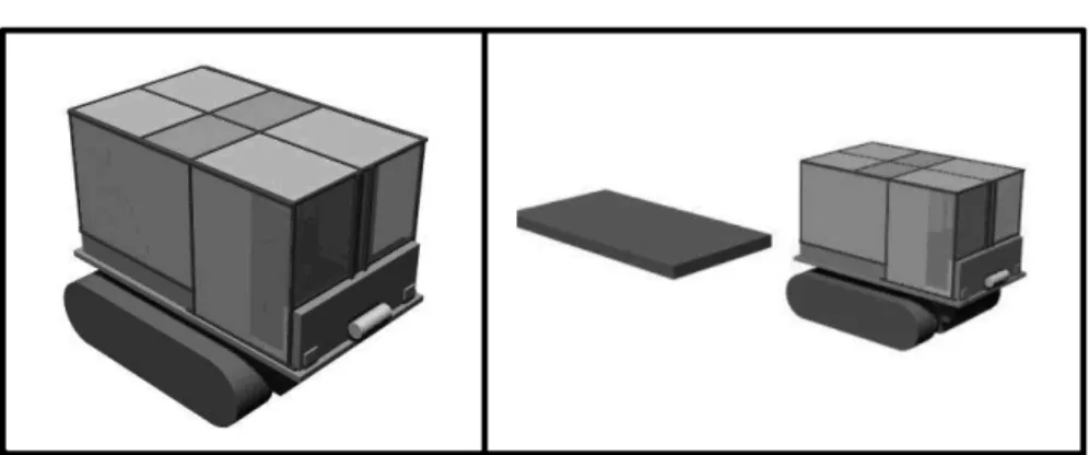
When designing and building MARVIN I, many design decisions such as electric versus gas powered engine, the type of vehicle, tracked versus wheeled, etc. had to be made without the ability to test in the same conditions in which it had to run. As a result, a virtual prototype of MARVIN I was created and tested in simulation. MSC.visualNastran 4D [25] was used for both the modeling and simulation of the vehicle. Figure 5 shows the model that was created for performing platform and tow-ing tests. The model does not perfectly match the actual vehicle, however, as there are many shapes and contours that are difficult and unnecessary to model. Also, the weight distribution of the vehicle was not completely known. The weight of the ve-hicle was evenly distributed around the base of the veve-hicle when the exact weight was known. The model for the antenna was created simply as a flat rectangular box, also shown in Figure 5.
The simulation experiments were designed to answer some specific questions about rover performance. First, what should the starting point be for the safety pa-rameters? The safety parameters included the maximum slope the rover could climb (the pitch angle) and the point at which the rover would roll over (the roll angle), and how would the rover handle while performing basic movements and with different load configurations? The results from these tests are described in [2], along with a full description of the modeling and testing process. Software and control will be discussed in the next section, as it was inherited by the second version of the robot: MARVIN II.
Fig. 5 Tracked vehicle model used for each simulation experiment (left), and the model towing an antenna sled.
2.3 MARVIN II
In order to address some of the limitations of MARVIN I [5, 19], MARVIN II, shown in Figure 1, was designed and built. Many of the decisions made regarding the design of the new robot were traceable to the lessons learned from MARVIN I [5]. MARVIN II was built using a RangeRunner All Terrain Vehicle (ATV) from TerraTrack [35] as the mobile platform base vehicle. The new vehicle has a 22.9 centimeters ground clearance, a 32 horsepower diesel engine, and a hydrostatic dif-ferential drive system. Hydraulic motors with built-in speed sensors allow for a finer control. Turns can be produced by speeding up one side, slowing down one side, or both. This improves the system in two ways: (1) horsepower is not lost to braking, and (2) one track no longer has to be dragged in order to turn. Another difference is that the new base vehicle is built with tracks whereas the first is a six-wheeled vehicle with a track kit. The tracks on MARVIN I had a tendency to detach when turning on hard surfaces.
The sensor suite of MARVIN II is quite similar to its predecessor. The weather station has been eliminated in place of a ground-based solution. The camera no longer pans and tilts, but rather has a fixed mount because the motors could not handle the vibration caused by a moving vehicle on the ice sheet. Speed sensors have been integrated with the hydraulic motors used to drive the vehicle. Each speed sensor provides a fixed number of pulses per revolution, which is used to determine the speed of each track. During early development of MARVIN II, a Garmin [14] handheld GPS receiver was used in place of the Topcon GPS. The Topcon GPS receiver was later utilized, but no longer in RTK differential mode due to the longer paths required during the 2005/2006 Antarctic field season.
A control box has been constructed to house an embedded control system, in-ternal robotic sensors, and the power supplies for the various subsystems. Toggle switches allow the various subsystems to be powered individually. I/O ports such as USB, RS232, and Ethernet are provided such that multiple computers and external devices may be integrated with the control box. An embedded controller was
con-structed to handle low-level control of the robot. The embedded controller utilizes a Xilinx Virtex-II Pro [41], which is equipped with FPGAs and dual embedded Pow-erPC processors. Custom I/O boards were constructed to handle communication between the controller, robotic components, and the control box’s user interface. Figure 6 shows MARVIN II’s actuator setup for autonomous navigation as well as the custom control box. Figure 7 displays the robot’s capabilities for mounting data acquisition equipment.
Fig. 6 MARVIN II’s actuator setup for autonomous navigation (left), and custom control box housing the embedded controller and other components (right).
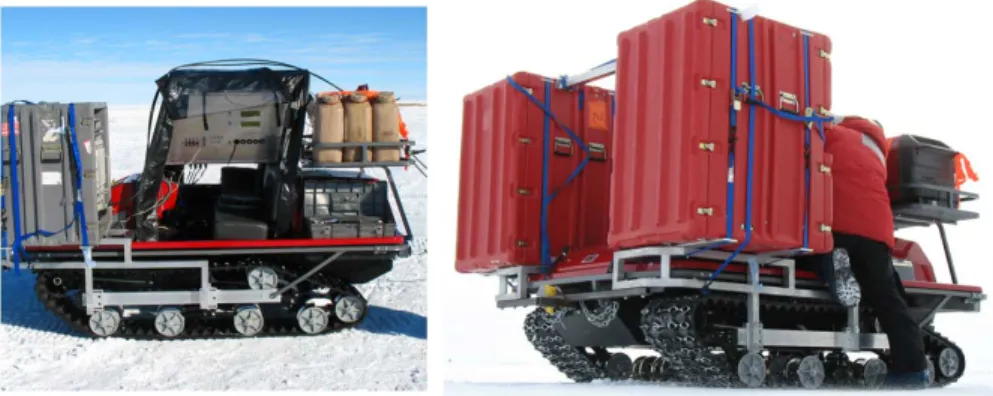
Fig. 7 MARVIN II platform with environmental enclosure, radar crate mounted on the front, and additional fuel on the back (left); and larger crates mounted on both sides of the custom aluminum frame (right).
The control system is divided between the embedded controller to control the speed of the tracks and a laptop that communicates with the embedded controller. The laptop determines where and at what speed the vehicle should move. The laptop uses a wireless network to communicate remotely. Unlike MARVIN I, the new con-trol software is written such that the two levels of concon-trol are decomposed from the original monolithic control system. At the highest layer, the list of waypoints is eval-uated and the waypoint navigator is given a new path to traverse. At the waypoint navigator layer, the sensors are monitored to determine and assign desired speeds for each track in order to drive the robot toward the path. Finally, at the lowest level, the embedded controller adjusts the actuator state until the desired speed is reached. This modularity allows the laptop to control the higher level actions of the robot such as setting the desired speed of each track, performing obstacle avoidance, and making route corrections. The embedded controller handles the lower-level control which attempts to keep each track moving at the requested speed while adjusting for bumps, hills, or anything that might hinder the speed of the tracks.
2.4 Software Architecture
A software application programming interface (API) was developed for PRISM and CReSIS mobile robotics research. The API was designed with an emphasis on porta-bility, robustness, and maintainability. As the underlying hardware of the mobile robot changes, the overall structure of the software system should remain intact and only require minor changes to adapt to the new hardware. The software libraries should also be general enough so that they could be utilized for a variety of mobile robots.
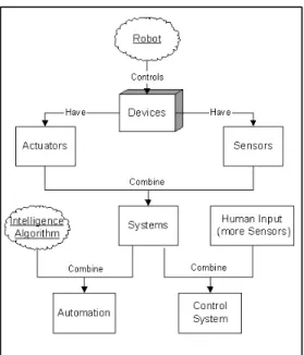
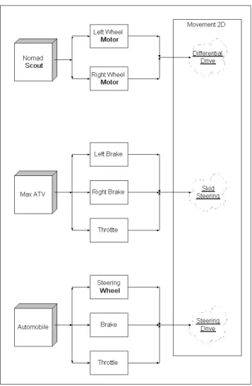
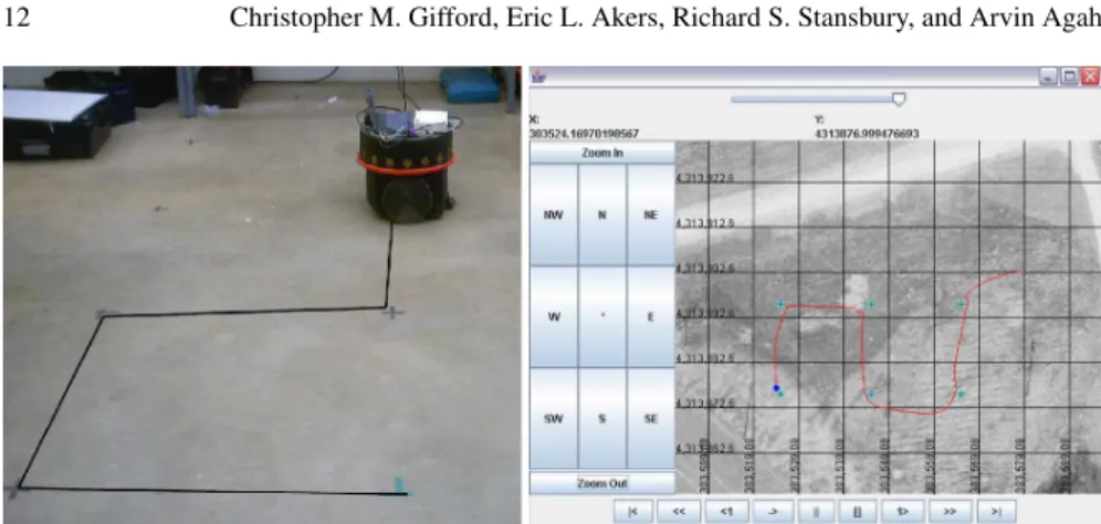
Figure 8 presents the robot API. Devices are modeled as either sensors or actua-tors, and several abstract classes for each exist. When implementing for a particular robot, the abstract sensor classes are implemented as drivers for the particular com-ponent. By using these abstract classes, it is possible to change the robotic platform while maintaining the same control system and automation software, utilizing the same intelligence algorithms. Figure 9 shows the mapping from each platform to a generic control system type. Figure 10 demonstrates the execution of software to guide a robot to move in an “S-pattern” on both a Nomadic Scout testbed and the MARVIN I polar rover.
The primary advantage of creating a reusable architecture for robot software development is to simplify testing the robot. The same algorithms may be ported between simulation, testbeds, and the field robots. When operating large mobile robots, small tests to prove control logic can become quite logistically challenging without sufficient use of prototypes, and this software helped bridge the necessary gap to do so. The same challenge holds for robots for polar regions.
Fig. 8 Robot API for PRISM/CReSIS mobile robots.
2.5 North Greenland Ice Core Project (GRIP) Camp Operations
Research during the Greenland 2003 field season focused on testing each of the in-dividual components of MARVIN I. Components were subjected to a deep freeze upon arrival on the ice sheet, and each was tested to ensure that it could reliably operate within the polar conditions. The rover was tested over several long-range traversals to determine how it handled when maneuvering on the snow. Figure 11 shows MARVIN I towing a prototype radar sled across the ice sheet. MARVIN I be-came stuck in snow only once. During the North GRIP camp [27] experiments, the sensors proved reliable. Figure 11 also shows the laser range-finder being tested by imaging a man-made snow wall. Other experiments included attempting to detect a simulated crevasse with the laser range-finder, which failed to yield positive results. Evaluation of the GPS receiver was performed to determine sufficient satellite cov-erage. From the results, it was clear that the minimum four necessary GPS satellites were available at all times.
2.6 Summit Camp Operations
After a year of work, MARVIN I was sent back to Greenland in the Summer of 2004 to test its automation. It was integrated with a radar system such that it would au-tonomously move across the ice sheet following a precise path so that radar data
Fig. 9 Mapping of platform to actuator API class to control systems.
could be collected. Unlike the previous experience at North GRIP, it was much warmer at the Summit Camp in 2004. As a result, the rover became stuck peri-odically. This happened most frequently during turns in which one of the tracks was stopped. The camera’s pan-tilt motor also failed due to excessive vibrations. Ulti-mately, MARVIN I’s transmission failed due to the payload being too heavy, and possibly a buildup of ice on the robot’s axles. These were lessons learned that were then applied to the MARVIN II polar robot design.
Fig. 10 Nomadic Scout testbed (left) and MARVIN I (right) performing ”S-pattern” using identical control software.
Fig. 11 Evaluation of MARVIN I systems at North GRIP, including using a laser range-finder to image a snow wall (left) and towing a mockup radar array (right).
2.7 West Antarctic Ice Sheet (WAIS) Divide Camp Operations
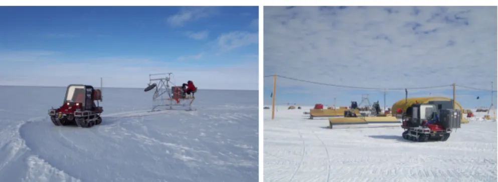
Having learned lessons from the MARVIN I experiments in Greenland, MARVIN II was deployed in Antarctica in 2006 to support mono-static and bi-static radar appli-cations. Figure 12 shows the MARVIN II rover towing two different radar systems in the field. MARVIN II is the current ground-based robot used by CReSIS for polar field expeditions.
Figure 13 illustrates the deployment of the two robots in the field. The left fig-ure plots the movement of MARVIN I between two waypoints with 25 meter grid spacing. Despite a high-end GPS providing centimeter-level accuracy, MARVIN I could not be mechanically controlled to provide a sufficiently straight path for au-tonomous radar survey. This demonstrates the impact of its transmission failure. The middle figure plots MARVIN II traversing between two waypoints with and without high-end GPS enabled with a 5 meter grid separation. Without RTK GPS, MARVIN II oscillated about the line. With the high-end GPS enabled, the amplitude of oscillation about the line was dramatically reduced, as shown in Figure 13. The
Fig. 12 MARVIN II rover towing a radar sled for a mono-static application (left) and a radar sled for a bi-static application (right) in Antarctica.
Fig. 13 Navigation results for MARVIN I with 25 meter resolution (left), MARVIN II straight line with 5 meter resolution (middle), and MARVIN II turn patterns with 5 meter resolution (right).
right image in Figure 13 plots (with 5 meter grid spacing) MARVIN II’s path as it performs a turn maneuver to switch between paths.
3 Robotics-Based Approaches to Seismic Surveying
Seismic sensors, also known as geophones, are sensors which transfer vibration waves as a series of analog signals based on the composition of the material beneath the surface and the travel times of the measured seismic waves. Widely used for oil exploration, geophones are activated by a seismic source, which can range from striking the ground to a very large explosion or a natural geologic event. The source sends elastic vibration energy down into and through the subsurface so as to even-tually reflect and refract back after interaction with the internal layers. Based on the travel times, wave velocities, and the received signals from a series of geophones, Seismologists can digitize, filter, and analyze the results to learn such facts as water table depth, fault location, and rock layer boundaries. The refracted and reflected paths can provide structural information of the subsurface [28]. The physical
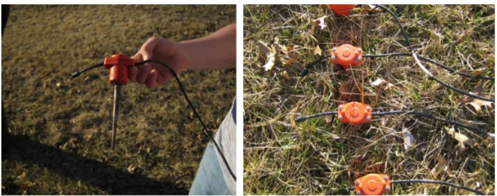
prop-erties of the rocks and beds affect travel times of seismic waves. These travel times, along with the waveform and spectra, are then used to deduce information about the subsurface and internal layering. Various styles and models of seismic sensors exist for many applications on land, snow, and at sea. A single geophone and linear array of deployed geophones are shown in Figure 14.
Fig. 14 Spiked geophone (left), and several deployed by inserting the spikes into the surface (right).
Deployment of geophones translates into how each is inserted into the ground (or alternatively, rests on the surface). During manual operations involving tens or hun-dreds of geophones, each is typically stepped on or hand-pressed into the ground. If necessary, holes are dug prior to deployment to create a shelter for the sensor to record its data. This is a timely and arduous task, especially when performed in a polar environment. Coupling of the geophones with the ground directly affects the data quality and frequencies that can be recorded. Geophones must also be arranged in a centimeter-level precision grid of equal spacing while being oriented no more than 10ofrom the Earth’s gravitational vertical.
Seismic arrays can be formed to acquire a map of the subsurface, allowing de-tailed imaging at many different resolutions and depths. Higher frequencies and close (sub-meter to tens of meters) spacing results in a highly detailed, shallow image of the subsurface. Deeper imaging requires sparse deployment and long dis-tances from a powerful source, with spacing ranging from hundreds to thousands of meters. Furthermore, high frequency acquisition translates into more accurate im-ages. If geophones are positioned in a straight line, a seismic survey will result in a two-dimensional (2D) image/slice of the subsurface. If the geophones are aligned in a square or rectangular grid pattern, a three-dimensional (3D) view of subsurface characteristics will result. A fourth dimension, namely time, can be introduced to image movement of the subsurface and materials.
3.1 Related Work
Very little work involving robotic deployment and retrieval of seismic sensors has been done to date. However, work done in regular environments can provide helpful information. As stated in [20], the future of seismic surveying on land is the elimi-nation of cables. Seismic networks can also be of less weight and easily scalable in terms of network size, structure, and shape.
The University of Kansas Geology Department recently developed an “autojug-gie” [37] capable of planting 72 geophones in 2 seconds using a hydraulic press and structured array system. Several variations of the autojuggie have also been developed and field-tested [33]. These variations include automated deployment us-ing farm equipment and deployment of closely-spaced lines of seismic sensors for ultra-shallow imaging. Structures were used to simultaneously press all sensors into the ground, and simultaneously retrieve all geophones when finished. Care was also taken to try to reduce crosstalk between sensors through the deployment structures. These approaches are still human-operated in that they use existing farm equipment and vehicles as a means for deployment and retrieval. Scalability and robustness of this approach is limited as well.
Land streamers are a method inherited from the marine seismic community, which deploy a series of geophones by dragging them along the surface. Acquisition takes place when stopped, where all geophones typically rest on metal plates rather than being physically inserted into the ground. This increases deployment efficiency by reducing the time required for insertion and orientation of the sensors, as well as reducing transportation time from one site to another. In [32], multiple land stream-ers were pulled alongside each other at the same time using an ATV. Individual land streamers were spaced equidistant from one another to a towing structure so as to create a wider 2D array. Results were acceptable for relaxed seismic requirements, but would not be applicable under higher frequency situations. Other efforts have also been published [13, 22, 31] that employed single streamers in a polar setting, or specifically designed for shallow data acquisition [38, 39]. Survey requirements and weather conditions dictated the geophone spacing, streamer length, and materi-als used to construct the streamers. Several streamer designs have been attempted in these works, ranging from the 1970’s to the present. The Kansas Geological Survey made their land streamer more rugged by encasing it and all wiring in a fire hose [21].
NASA, working with Georgia Tech and Metrica, Inc., developed an Extra-Vehicular Activity Robotic Assistant [8] capable of being handed a geophone and in-serting it into soil using a seven degree-of-freedom manipulator and a three-fingered gripper [24]. The 4-wheeled mobile robot could not perform the full deployment task and was not made to retrieve the planted geophones. The main purpose of this robot was to assist activity-suited humans in the field by performing some tasks on its own. A trailer containing the geophones was pulled so the human could hand them to the robot or store other various supplies.
3.2 Robotics-Based Approaches
Many possible mechanisms exist for deployment and retrieval of seismic sensors [15, 16]. Automating the process makes detailed imaging on many scales much more feasible.
Individual Deployment
Individual deployment covers those methods that deploy and retrieve a single geophone at a time. This mechanism could be a robotic arm, crane-like apparatus, air-powered device, planter, or any other form of pick-and-place device. In many planting, weeding, and picking projects, robotic manipulators are utilized to help automate the process. This type of mechanism is responsible for pressing into, ori-enting, and pulling from the ground all seismic sensors and placing them in a trans-port area, charging station, or organized rack. Size, shape, and weight influence the overall design of platform(s) performing the task. Issues with this category involve orientation, positioning, and weather. Autonomously dealing with and keeping track of the tangling maze of seismic cable also represents a formidable challenge. A pos-itive aspect of this approach is the millimeter repeatability and precision that ma-nipulators offer. However, finding and retrieving geophones, manipulator payload, required pushing power, and gripping the geophone are all major difficulties inher-ent to this approach.
Array Deployment
The array deployment involves an array to deploy and retrieve a set of geophones, their cables, and all necessary storage equipment. Seismic sensors would be pre-set into the array, taken to the field location, and simultaneously (e.g., hydraulically) pressed into the ground at equal spacing, tilt, and elevation. When ready for re-trieval, the structure is raised to remove the sensors from the ground. Multiple ar-rays could be pieced together to record larger areas. The design could also permit variable sensor spacing to perform different resolution imaging. Geophone spacing, orientation, and deployment depth are therefore controlled for the entire seismic array. Scalability in terms of size and imaging resolution is lacking due to being pre-built, however, and this approach is also still wired.
Land Streamers
The idea of land streamers came from marine seismic surveying, which involves constantly towing marine streamers under water with use of pulse guns for the sound source. Land streamers are a non-insertion seismic method where geophones are wired in series and towed on the surface to acquire seismic data. When the recording location is reached, the towing vehicle stops so that seismic acquisition can take place. One or more of these streamers can be towed in parallel to cover larger areas and perform 2D or 3D imaging.
Autonomous seismic acquisition can then be accomplished with, for example, the MARVIN II robot. The Webots [12] simulation environment was used to test GPS waypoint navigation, driving, and turning algorithms, whereas MSC visualNastran
[25] was employed to simulate pulling and drag abilities of our autonomous rovers. Figure 15 shows a MSC visualNastran simulation involving three streamers, where each box represents an enclosed geophone.
Fig. 15 Simulation image of an autonomous robot towing a three-streamer array, used for studying towing of streamers and how turning affects strain of the towing structure and travel of the streamer components.
This mechanism could extend to cover a long distance behind the rover as well as widen coverage width by using multiple streamers. An attractive aspect of this category is the ability to choose and change spacing of sensors within and between streamer lines. Other advantages of this approach are its ease of transport, efficiency, simplicity, and no need for geophone insertion. The main advantage to these types of systems is speed and the amount of seismic data that can be recorded with fewer personnel. The unattractive characteristic of this approach is its lower coupling. This may cause the geophones to miss higher frequencies, resulting in less detailed seis-mic images. Some research has shown that, in some environments, performance between conventional geophones and land streamers are very similar.
Hybrid Streamers
It has been proposed that a hybrid combination of land streamers with increased coupling would be a good alternative [15]. There are several design options to in-crease hybrid streamer coupling:
• Employ a trenching or plowing attachment to prepare the ground to drag the streamers below the surface for wind protection and to rest flat for orientation purposes;
• Add weight to each streamer node; • Change plate size and/or geometry;
• Increase the surface area the plates have with the ground;
• Heat streamer plates for snowy/polar environments so the melt can refreeze to ice, giving a more rigid surface contact for the plates; and
Accordingly, a furrowing, plowing, or trenching apparatus could be attached to a mobile robot. The robot would power all equipment, have seismographs onboard for seismic data conversion and storage, and have a data cable which would act as both the data transmission and communication medium for the entire system.
The simulation images in Figure 16 illustrate several variations and configura-tions that could be utilized. One or more robots could be used and each could tow one or more parallel streamer lines. A single robot can tow a single hybrid streamer, or multiple robots can tow several parallel hybrid streamers and work together to image larger areas. The advantages of such an approach are better coupling, faster travel, and the potential to collect much more data with far fewer personnel involved. Complex coordination, communication, and node collisions are essentially avoided and there is no added attachment/detachment complexity for the streamer to the robot. Disadvantages to this approach are a single point of failure and overcoming coupling issues. Hybrid streamers represent a new seismic technique that has not yet been fully designed or attempted in modern surveying. CReSIS is in the process of designing and implementing these hybrid techniques [18] for polar deployment.
(a) Single robot, single hybrid streamer (b) Single robot, hybrid streamer array
(c) Multiple robots, single hybrid streamers (d) Multiple robots, hybrid streamer arrays
Multi-Robot Seismic Surveying Team
Based on the demonstrated success of multi-robot systems (distributed robotics) [1, 7], we have proposed use of a robot seismic surveying team. The multi-robot seismic surveying approach involves a team of several autonomous, mobile robots that are smaller in size to deploy geophones and traverse the environment. They work together to precisely align into a seismic grid pattern. Each robot repre-sents a mobile node that deploys and retrieves its own geophone. Power is provided by onboard sources, where each robot contains the necessary digitizing, storage, and communication hardware for seismic acquisition.
A mobile robot can inject into or place a geophone onto the ground while pro-tecting the deployed sensors from the wind and weather using an environmental enclosure. Team size can be relatively small, such as a 25-robot team forming a 5x5 seismic grid, or extremely large, consisting of potentially hundreds of robots forming grids of any size, shape, and spacing for different seismic resolution appli-cations.
There are various ways that the team could move into position. Robots could move one at a time in a certain fashion, by rows or columns, or dynamically align while all moving at once. Positioning one robot at a time takes longer, but could help increase accuracy and reduce collisions [17]. Dynamically forming the seismic grid would take less time and would likely be a more flexible solution, but would suffer from inherently being less precise.
Figure 17 illustrates a shape formation scenario in simulation. The robots coordi-nate which GPS positions they travel to based on a desired grid shape and spacing, as provided by the main robot.
Fig. 17 Simulation images showing a team of mobile robots forming a square seismic grid, one-by-one from top-right to bottom-left.
The advantages of the multi-robot seismic sensor network approach are that it would be faster than a human team for large arrays, removes cumbersome wires from the system, and allows safe remote sensing while being able to dynamically adjust to the environment. This distributed methodology removes the single point of failure. This is also a new seismic method that has not yet been attempted, mainly because it remains too challenging at this time. The main bottlenecks lie in highly
precise alignment of a team of mobile robots at any scale and any environment [17], along with properly aggregating the seismic data. This is the most desirable approach based on its mobility and ability to image at any resolution, shape, and scale. This might also provide faster network assembly, especially for a large and remote team. Dropping the robot team from an aerial vehicle to assemble, record, and perform multiple missions represents a futuristic option in this category. A de-sign has been proposed for such a mobile robot team platform, as well as precise grid formation schemes such that the team could form a precise seismic grid one at a time or in a dynamic fashion [15, 17]. This category of seismic sensing has not been formally performed, but is currently being studied at CReSIS.
Seismic TETwalker Mobile Robot
The NASA/Goddard Space Flight Center in Maryland is developing a new ap-proach for the sustainable and affordable robotic exploration of the solar system: the Autonomous Nano-Technology Swarm (ANTS) [11]. The basic unit of the structure is a tetrahedron consisting of nodes interconnected with struts that can be reversibly and/or partially deployed or stowed to allow forward motion on a surface at a con-trollable scale or gait. 3D networks are formed from interconnecting reconfigurable tetrahedra, making structures which are scalable, massively parallel systems. These robots have been thusly named Tetrahedral walkers, or TETwalkers.
With these aspects in mind, the 4-TETwalker’s center node that it uses to shift its center of gravity has been studied for geophone deployment [9, 30, 40]. As the robot could potentially deploy through any “face” of its tetrahedral structure after toppling, a center node was designed for this purpose with angled faces parallel to the faces of the TETwalker’s outer shape. The corresponding vertical strut is used to push/insert the sensor into or onto the surface. Lengthening and shortening struts allow the deployment node to precisely place the geophone, as well as vertically orient it for proper data acquisition on tilted surfaces.
The design utilized the 4-TETwalker’s center node to house one or more geo-phones, each with a dedicated spike or surface plate. The robot could then place the center node down onto the ground by extending the strut that is vertical during deployment. Figure 18 shows models of the center node, designed with a geophone and spike for downward deployment using any side of the 4-TETwalker.
Fig. 18 Center node design with geophones and spikes (far left image), and the upright 4-TETwalker vertically aligning (second image from left) and deploying the downward-pointing geophone in a gimbaled manner (right two images).
Deployment and mobility simulations were conducted to study the dynamics of 4-TETwalker motion and strut extension properties for toppling. The struts are mod-eled as lightweight actuators capable of extending and retracting given the weight of the system. Figures 19 shows models used for deployment and mobility simulations. Further simulation studies are taking place to improve these models.
Fig. 19 Simulation images of models used to study the physical characteristics of center node deployment and retrieval.
4 Conclusion
This chapter described the research efforts at the University of Kansas and CReSIS, focused on developing single- and multi-robot systems for remote sensing and ex-ploration applications in polar environments, with extensions possible to planetary missions. These systems represent established building blocks for further research in the areas of robotics-based seismic surveying and related robotic deployment de-signs, and mobile robots for autonomous data acquisition in extreme polar settings. Using such robotic systems can decrease human involvement and reduce risk of science platforms in unexplored environments.
Ground-based remote sensing experiments have been extremely limited in plan-etary robotics due to the combination of lower reliability, increased risk, and limited technical readiness levels. As we explore further from Earth, increased autonomy is desired to compensate for the downtime associated with communication delays. We envision autonomous mobile seismic and radar mapping networks on other planets, such as Jupiter’s icy moon Europa, to explore their subsurface characteristics. Infor-mation that can be acquired from such experiments could provide insight into the developmental history of other planets, and also aid in the quest for better under-standing of the solar system.
As part of this work, novel designs and algorithm simulations demonstrate that a multi-robot seismic surveying team represents a futuristic approach for remote sensing on Earth and other planets. We have developed a low-cost multi-robot ex-ploration and mapping team that will be used to extend this task from simulation to
reality. We also plan to scale the system up by building more robots, further research low-cost sensing systems, and introduce more sophisticated multi-robot coordina-tion and exploracoordina-tion techniques. We would also like to integrate more formal science and sensor components so as to perform distributed science experiments while ex-ploring an unknown environment. Polar rovers have provided CReSIS the unique opportunity to safely and remotely acquire radar and seismic data. This data are be-ing used to study the effects of climate change on the ice sheets and the inherent impact of sea level rise on our planet. The University of Kansas and CReSIS will continue advancing these systems for polar and planetary exploration and subsur-face mapping.
Acknowledgements The authors would like to thank Dr. Georgios Tsoflias and Anthony Hoch of CReSIS for helpful discussions on seismic surveying; Hans Harmon for his work in development of the polar rovers; and the ANTS/TETwalker team associated with the NASA Goddard Space Flight Center for discussions about the TETwalker design. This material is based upon work supported by the National Science Foundation under Grant No. ANT-0424589. Any opinions, findings, and conclusions or recommendations expressed in this material are those of the authors and do not necessarily reflect the views of the National Science Foundation.
References
1. Agah, A., Bekey, G.A.: Phylogenetic and Ontogenetic Learning in a Colony of Interacting Robots. Autonomous Robots4(1), 85–100 (1997)
2. Akers, E.L., Agah, A.: Design and Simulation of a Polar Mobile Robot. Journal of Intelligent Systems17(4), 379–404 (2008)
3. Akers, E.L., Harmon, H.P., Stansbury, R.S., Agah, A.: Design, Fabrication, and Evaluation of a Mobile Robot for Polar Environments. In: IEEE International Geoscience and Remote Sensing Symposium (IGARSS), pp. 109–112. Proceedings of the IEEE International Geoscience and Remote Sensing Symposium, Anchorage, Alaska (2004)
4. Akers, E.L., Stansbury, R.S., Agah, A.: Long-term Survival of Polar Mobile Robots. In: Pro-ceedings of the 4th International Conference on Computing, Communications and Control Technologies (CCCT), vol. II, pp. 329–333. Orlando, FL (2006)
5. Akers, E.L., Stansbury, R.S., Agah, A., Akins, T.L.: Mobile Robots for Harsh Environments: Lessons Learned from Field Experiments. In: Proceedings of the 11th International Sympo-sium on Robotics and Applications (ISORA), pp. 1–6. Budapest, Hungary (2006)
6. Arcone, S.: Personal Communications. Cold Regions Research and Engineering Lab (CR-REL), Hanover, New Hampshire (2003)
7. Bekey, G.A., Agah, A.: Group Behavior of Robots, second edn., pp. 439–445. Shimon Y. Nof (Ed.) Handbook of Industrial Robotics. John Wiley & Sons Inc., New York, New York (1999) 8. Burridge, R.R., Graham, J., Shillcutt, K., Hirsh, R., Kortenkamp, D.: Experiments with an EVA Assistant Robot. In: Proceedings of the 7th International Symposium on Artificial Intel-ligence, Robotics and Automation in Space (I-SAIRAS-03) (2003)
9. Carmichael, B.L., Gifford, C.M.: Modeling and Simulation of the Seismic TETwalker Con-cept. Tech. Rep. CReSIS-TR-134 (2007)
10. CReSIS: Center for Remote Sensing of Ice Sheets. URL: http://www.cresis.ku. edu/(2006)
11. Curtis, S., Mica, J., Nuth, J., Marr, G.: ANTS (Autonomous Nano Technology Swarm): An Artificial Intelligence Approach to Asteroid Belt Resource Exploration. In: Proceedings of the 51st International Astronautical Congress. Rio de Janeiro, Brazil (2000)
12. Cyberbotics: Webots 5. URL:http://www.cyberbotics.com/(2006)
13. Eiken, O., Degutsch, M., Riste, P., Rod, K.: Snowstreamer: An Efficient Tool in Seismic Ac-quisition. First Break7(9), 374–378 (1989)
14. Garmin Ltd.: GPSMAP 76S. URL: http://www.garmin.com/products/ gpsmap76s(2005)
15. Gifford, C.M.: Robotic Seismic Sensors for Polar Environments. Master’s Thesis, Department of Electrical Engineering and Computer Science, University of Kansas (2006)
16. Gifford, C.M., Agah, A.: Robotic Deployment and Retrieval of Seismic Sensors for Polar Environments. In: Proceedings of the 4th International Conference on Computing, Commu-nications and Control Technologies (CCCT), vol. II, pp. 334–339. Orlando, FL (2006) 17. Gifford, C.M., Agah, A.: Precise Formation of Multi-Robot Systems. In: Proceedings of
the IEEE International Conference on Systems of Systems Engineering (SoSE), pp. 1–6. San Antonio, TX (2007)
18. Gifford, C.M., Agah, A., Tsoflias, G.P.: Hybrid Streamers for Polar Seismic. Eos Trans. AGU 87(52) (2006)
19. Harmon, H.P., Stansbury, R.S., Akers, E.L., Agah, A.: Sensing and Actuation for a Polar Mo-bile Robot. In: Proceedings of the International Conference on Computing, Communications and Control Technologies (CCCT), vol. IV, pp. 371–376 (2004)
20. Hollis, J., Iseli, J., Williams, M., Hoenmans, S.: The Future of Land Seismic. Hart’s E & P 78(11), 77–81 (2005)
21. Kansas Geological Survey: LandStreamer. URL: http://www.kgs.ku.edu/ Geophysics2/Equip/LandStreamer/LandS4.htm(2006)
22. King, E.C., Bell, A.C.: A Towed Geophone System for use in Snow-Covered Terrain. Geo-physical Journal International126(1), 54–62 (1996)
23. KU PRISM Team: PRISM Home: Polar Radar for Ice Sheet Measurements. URL:http: //www.ku-prism.org(2004)
24. Metrica, Inc.: Mars Manipulator. URL:http://www.metricanet.com/mars.htm
(2006)
25. MSC Software: visualNastran 4D R2 User Manual (2002)
26. National Science Foundation: Amundsen-Scott South Pole Station. URL:http://www. nsf.gov/od/opp/support/southp.jsp(2006)
27. Niels Bohr Institute: NGRIP: North Greenland ice core project. URL: http://www. glaciology.gfy.ku.dk/ngrip/index eng.htm(2005)
28. R. E. Sheriff and L. P. Geldart: Exploration Seismology, second edn. Cambridge University Press (1995)
29. Recreative Industries: Buffalo All Terrain Truck. URL:http://www.maxatvs.com/
(2004)
30. Ruiz-Carrion, I., Gifford, C.M.: Detailed Modeling of Designs for the Polar Seismic TET-walker. Tech. Rep. CReSIS-TR-132 (2007)
31. Sen, V., Stoffa, P.L., Dalziel, I.W.D., Blankenship, D.D., Smith, A.M., Anandakrishnan, S.: Seismic Surveys in Central West Antarctica: Data Processing Examples from the ANTALITH Field Tests. Terra Antarctica5(4), 761–772 (1999)
32. Speece, M.A., Miller, C.R., Miller, P.F., Link, C.A., Flynn, K.F., Dolena, T.M.: A Rapid-Deployment, Three Dimensional (3-D), Seismic Reflection System. Montana Tech. Prototype Design Proposal (2004)
33. Spikes, K., Steeples, D., Ralston, M., Blair, J., Tian, G.: Common Midpoint Seis-mic Reflection Data Recorded with Automatically Planted Geophones. URL:
http://www.dot.ca.gov/hq/esc/geotech/gg/geophysics2002/ 037spikes cmp auto plants.pdf(2001)
34. Stansbury, R.S., Akers, E.L., Harmon, H.P., Agah, A.: Survivability, Mobility, and Function-ality of a Rover for Radars in Polar Regions. International Journal of Control, Automation, and Systems2(3), 334–353 (2004)
35. TerraTrack Inc.: RangeRunner by TerraTrack. URL:http://www.terratrack.com
36. Topcon Positioning Systems, Inc.: Legacy GPS+ Receiver. URL:
http://www.topconeurope.com/index.asp?pageid= 12166e1461284b7ca5e68c4f0257448d(2008)
37. Tsoflias, G.P., Steeples, D.W., Czarnecki, G.P., Sloan, S.D., Eslick, R.C.: Automatic Deploy-ment of a 2-D Geophone Array for Efficient Ultra-Shallow Seismic Imaging. Geophysical Research Letters (2006)
38. Van der Veen, M., Green, A.: Land Streamer for Shallow Seismic Data Acquisition: Evaluation of Gimbal-Mounted Geophones. Geophysics63, 1408–1413 (1998)
39. Van der Veen, M., Wild, P., Spitzer, R., Green, A.: Design Characteristics of a Seismic Land Streamer for Shallow Data Acquisition. In: Extended Abstracts of the 61st European Associ-ation of Geoscientists and Engineers Conference and Technical Exhibition, pp. 40–41 (1999) 40. Wade, U.B., Gifford, C.M.: Investigation of Power Sources for the Polar Seismic TETwalker.
Tech. Rep. CReSIS-TR-133 (2007)
41. Xilinx, Inc.: Xilinx: Virtex-II Pro FPGAs. URL: http://www.xilinx.com/ products/silicon solutions/fpgas/virtex/virtex ii pro fpgas/ index.htm(2005)