SIMULATING AND PROTOTYPING SOFTWARE DEFINED NETWORKING (SDN) USING MININET APPROACH TO OPTIMISE HOST COMMUNICATION IN
REALISTIC PROGRAMMABLE NETWORKING ENVIRONMENT.
by
LINDINKOSI LETHUKUTHULA ZULU 61366935
submitted in accordance with the requirements for the degree of
MAGISTER TECHNOLOGIAE: ELECTRICAL ENGINEERING (98988) FIELD OF SPECIALIZATION: COMPUTER NETWORKS MODELLING,
TELECOMMUNICATIONS in the
Department of Electrical and Mining Engineering
COLLEGE OF SCIENCE ENGINEERING AND TECHNOLOGY UNIVERSITY OF SOUTH AFRICA (UNISA)
SUPERVISOR: DR KINGSLEY OGUDO CO-SUPERVISOR: DR PATRICE UMENNE
NOVEMBER 2018
2 © University of South Africa November 2018
DECLARATION
I declare that SIMULATING AND PROTOTYPING SOFTWARE DEFINED NETWORKING (SDN) USING MININET APPROACH TO OPTIMISE HOST
COMMUNICATION IN REALISTIC PROGRAMMABLE NETWORKING
ENVIRONMENT is my own work and that all the sources that I have used or quoted have been indicated and acknowledged by means of complete references.
I further declare that I submitted the thesis/dissertation to originality checking software and that it falls within the accepted requirements for originality.
I further declare that I have not previously submitted this work, or part of it, for examination at Unisa for another qualification or at any other higher education institution.
________________________ November 8, 2018
3 © University of South Africa November 2018
COPYRIGHT CLASSIFICATION
© Copyright resides in the University of South Africa (UNISA) and Lindinkosi Zulu. In terms of the Copyright Act 98 of 1978, no part of this material may be reproduced, stored in any retrieval system, be transmitted in any form or be published, redistributed or screened by any means (electronic, mechanical, photocopying, recording or otherwise) without prior written permission from the University of South Africa. However, permission to use any material in this work that is derived from other sources must be obtained from the original source.
4 © University of South Africa November 2018
DEDICATION
I dedicate this dissertation to my son Nkazimulo Zulu whose birth gave me the courage to pursue these studies. This dissertation is also dedicated to my wife Thabisile Zulu who always believe in me even when I doubted myself.
5 © University of South Africa November 2018
ACKNOWLEDGEMENTS
Praises to God Almighty who has made it possible for me to reach this point in my life and gave me strengths to press on even on difficult times during my studies.
I wish to express my deep gratitude to my wife Thabisile for her constant support and believing in me. I would have not been able to complete these studies if it wasn’t for her time that was sacrificed when I was doing these studies.
Specifically, I would like to acknowledge the following people.
1. To my supervisors, Dr Kingsley Ogudo and Dr Patrice Umenne, thank you for your time, wisdom, support and guidance. I’m also humble by your support and involvement and the roles you played on the two conference papers that emanated from these studies. I will always be grateful to your contribution and support.
2. To the University of South Africa, thank you for giving me an opportunity to pursue these studies and the financial assistance with the conference papers presentations.
3. To Ian Kruger, thank you for believing in my dream and providing me with access to resources and tools used for these studies more especially EVE-NG.
4. I also like to express my deep gratitude to everyone who has contributed in various ways to the successful completion of these studies. From my friends, colleagues at NEC XON and my family at large, Thank you so much.
6 © University of South Africa November 2018
ABSTRACT
In this project, two tests were performed. On the first test, Mininet-WiFi was used to simulate a Software Defined Network to demonstrate Mininet-WiFi’ s ability to be used as the Software Defined Network emulator which can also be integrated to the existing network using a Network Virtualized Function (NVF). A typical organization’s computer network was simulated which consisted of a website hosted on the LAMP (Linux, Apache, MySQL, PHP) virtual machine, and an F5 application delivery controller (ADC) which provided load balancing of requests sent to the web applications. A website page request was sent from the virtual stations inside Mininet-WiFi. The request was received by the application delivery controller, which then used round robin technique to send the request to one of the web servers on the LAMP virtual machine. The web server then returned the requested website to the requesting virtual stations using the simulated virtual network. The significance of these results is that it presents Mininet-WiFi as an emulator, which can be integrated into a real programmable networking environment offering a portable, cost effective and easily deployable testing network, which can be run on a single computer. These results are also beneficial to modern network deployments as the live network devices can also communicate with the testing environment for the data center, cloud and mobile provides.
On the second test, a Software Defined Network was created in Mininet using python script. An external interface was added to enable communication with the network outside of Mininet. The amazon web services elastic computing cloud was used to host an OpenDaylight controller. This controller is used as a control plane device for the virtual switch within Mininet. In order to test the network, a webserver hosted on the Emulated Virtual Environment – Next Generation (EVE-NG) software is connected to Mininet. EVE-NG is the Emulated Virtual Environment for networking. It provides tools to be able to model virtual devices and interconnect them with other virtual or physical devices. The OpenDaylight controller was able to create the flows to facilitate communication between the hosts in Mininet and the webserver in the real-life network.
7 © University of South Africa November 2018
KEY TERMS
Software Defined Networking (SDN); Network Functions Virtualization (NFV); OpenDaylight Controller; Mininet; Linux Web Server; Mininet Wi-Fi; Application Delivery Controller (F5); Cloud Computing (Amazon Web Services); Python Script; Emulated Virtual Environment – Next Generation (EVE-NG)
8 © University of South Africa November 2018
LIST OF PUBLICATIONS
1. L. Zulu, K. Ogudo and P. Umenne, “Simulating Software Defined Networking Using Mininet to Optimize Host Communication in a Realistic Programmable Network”. Proceedings of the International Conference on Advances in Big Data, Computing and Data Communication Systems, 6-7th August 2018, Durban, South Africa, ISBN
978-1-5386-3059-4, IEEE Mauritius sub-section.
2. L. Zulu, K. Ogudo and P. Umenne, “Emulating Software Defined Network Using Mininet and OpenDaylight Controller Hosted on Amazon Web Services Cloud Platform to Demonstrate a Realistic Programmable Network”. Accepted for publication by the International Conference on Intelligent and Innovative Computing Applications (ICONIC 2018), Plaine Magnien, IEEE Mauritius sub-section, December 6-7. 2018
9 © University of South Africa November 2018
TABLE OF CONTENTS
DECLARATION ... 2 COPYRIGHT CLASSIFICATION ... 3 DEDICATION ... 4 ACKNOWLEDGEMENTS ... 5 ABSTRACT ... 6 KEY TERMS ... 7 LIST OF PUBLICATIONS ... 8 TABLE OF CONTENTS ... 9 TABLE OF FIGURES ... 11 LIST OF ABBREVIATIONS ... 12 CHAPTER 1 ... 14 1.1 INTRODUCTION ... 14 1.2 PROBLEM STATEMENT ... 15 1.2.1 Knowledge gap ... 15 1.3 STUDY FRAMEWORK ... 151.3.1 Research objectives and aims ... 15
1.3.2 Research/Core Questions ... 16
1.3.3 Benefit of the study ... 16
1.3.4 Delimitation of the study ... 17
1.4 LITERATURE REVIEW ... 18
1.4.1 Software Defined Networking ... 18
1.4.1.1 Background ... 18
1.4.1.2 Need for Software Defined Networking ... 20
1.4.1.3 Software Defined Networking Architecture ... 20
1.4.1.4 Application Plane ... 21
1.4.1.5 Control Plane ... 21
1.4.1.6 Data Plane ... 22
1.4.2 Network Function Virtualization ... 22
1.4.3 Mininet ... 23
1.4.3.1 Background ... 23
1.4.3.2 What is Mininet ... 24
1.4.3.3 Advantages of using Mininet ... 25
1.4.3.4 Mininet Installation ... 26
1.4.3.5 How does Mininet work ... 26
1.4.3.6 Mininet Topologies ... 29
1.4.3.7 Mininet Python Script ... 29
1.4.4 Mininet-WiFi ... 32
1.4.5 Other Related Work ... 32
CHAPTER 2 ... 34
2.1 METHODOLOGY ... 34
2.1.1 Logical Network ... 35
2.1.2 Virtualized network on EVE-NG (Emulated Virtual Environment – Next Generation) ... 37
10 © University of South Africa November 2018
2.1.4 F5 BIG-IP Virtual Edition (VE) ... 39
2.1.5 Listening tools to network parameters ... 42
2.1.6 Wireless Software Defined Network on Mininet-WiFi ... 43
2.1.7 Wired Software Defined Network on Mininet ... 44
2.1.8 OpenDaylight controller ... 46
CHAPTER 3 ... 51
3.1 IMPLEMENTATION OF MININET EMULATED NETWORK ... 51
3.1.1 Preparation of Juniper device ... 53
3.1.2 Preparation of OpenDaylight controller ... 55
CHAPTER 4 ... 57
4.1 RESULTS ... 57
4.1.1 Results for Emulated Wireless Software Defined Networking ... 57
4.1.2 Results for Emulated Wired Software Defined Networking ... 60
4.1.3 Results for Intergrated Softwared Defined Network in Real-Life (EVE-NG) ... 63
4.1.3.1 Network Testing ... 63 CHAPTER 5 ... 68 5.1 CONCLUSION ... 68 5.2 RECOMMENDATIONS ... 69 REFERENCES ... 70 APPENDICES ... 76
APPENDIX A: MININET PYTHON SCRIPT ... 76
APPENDIX B: MININET NET CLASS ... 78
APPENDIX C: MININET NODE CLASS ... 96
11 © University of South Africa November 2018
TABLE OF FIGURES
Figure 1. Traditional networking architecture ... 18
Figure 2. Software Defined Networking architecture ... 19
Figure 3. Network emulated in a single computer ... 24
Figure 4. Basic wireless network created in Mininet ... 27
Figure 5. Execution of “pingall” command ... 28
Figure 6. Mininet NODE class ... 31
Figure 7. Methodology framework ... 34
Figure 8. Logical network to test wireless SDN ... 36
Figure 9. Logical network to test wired SDN ... 36
Figure 10. Network on EVE-NG ... 38
Figure 11. Virtual server configuration ... 40
Figure 12. Monitor configuration ... 40
Figure 13. Pool configuration ... 41
Figure 14. Monitor results ... 41
Figure 15. Adding external interface on the Access Point (AP) ... 43
Figure 16. Logical Mininet-WiFi network ... 44
Figure 17. Postman "GET" node inventory API ... 45
Figure 18. OpenFlow virtual Switch (OvSwitch) ... 46
Figure 19. OpenDayligh controller architecture ... 48
Figure 20. OpenFlow virtual switch flow chart ... 50
Figure 21.. Logical network to test wired SDN ... 51
Figure 22. Deployed network on EVE-NG ... 52
Figure 23. Juniper device information ... 53
Figure 24. Juniper device netconf settings ... 54
Figure 25. Creating a netconf-connector payload ... 56
Figure 26. Connected netconf-connecter ... 56
Figure 27. TCP flow ... 58
Figure 28. Round Trip Time ... 58
Figure 29. Throughput ... 58
Figure 30. OpenFlow Channel messages captured with Wireshark ... 60
Figure 31. ODL-DLUX network topology ... 61
Figure 32. “Iperf” test results ... 61
Figure 33. Average throughput over 90ms ... 62
Figure 34. Configuring interfaces using netconf on "Postman" ... 63
Figure 35. Some of configured interfaces from restconf API ... 64
Figure 36. Some of configured interfaces from CLI ... 65
Figure 37. Configuration commit record ... 65
Figure 38. PC1 accessing webpage from Linux server ... 66
Figure 39. "Iperf test results between PC1 and Linux server ... 67
12 © University of South Africa November 2018
LIST OF ABBREVIATIONS
ADC: Application Delivery ControllerAP: Access Point
API: Application Programming Interface
AWS: Amazon Web Services BSS: Business Support Systems
CAPEX: Capital Expenditure
CLI: Command Line Interface DoS: Denial of Service
ETSI: European Telecommunications Standards Institute
EVE-NG: Emulated Virtual Environment – Next Generation Fs-SDN Flow simulator- Software Defined Networking GUI: Graphical User Interface
HA: High Availability
HTTP: Hypertext Transfer Protocol
IEEE: Institute of Electrical and Electronics Engineers IETF: Internet Engineering Task Force
IP: Internet Protocol
LAMP: Linux Apache MySQL PHP
LTM: Local Traffic Manager MAC: Media Access Control
MD-SAL: Model-driven Service Abstraction Layer NaaS: Network as a Service
NAT: Network Address Translation NETCONF: Network Configuration Protocol
NFV: Network Functions Virtualization NMS: Network Management System
13 © University of South Africa November 2018
NOS: Network Operating System ODL: OpenDaylight
ONF: Open Networking Foundation OPEX: Operating Expenditure
OSGI: Open Services Gateway initiative
OSS: Operations Support Systems OVS: Open Virtual Switch
OVSDB: Open Virtual Switch Database
PoC: Proof of concept QoS: Quality of Service
REST API: Representational State Transfer Application Programming Interface
SAL: Service Abstraction Layer SDN: Software Defined Networking TCP: Transmission Control Protocol
TCP/IP: Transmission Control Protocol/Internet Protocol UDP: User Datagram Protocol
VE: Virtual Edition
VLAN: Virtual Local Area Network VM: Virtual Machine
VTN: Virtual Tenant Network WiFI: Wireless Fidelity
14 © University of South Africa November 2018
CHAPTER 1
1.1 Introduction
Moving to Software Defined-based networking is not without its challenges. Converting from a proprietary to an open system involves more moving parts, including controllers, clients, orchestration systems, and business applications. In many cases, Software Defined Networking (SDN) components must interact with legacy components introducing further complexity. This has created a room for testbeds, which can be used to test the Software Defined Network before being implemented in real network to minimize down time and to provide a test environment, which is close to real world where issues can be identified and rectified. A suitable tool or emulator, which must produce close to real live situation, must be used to obtain outcomes, which can be implemented as is in real world.
This study is based on simulating a Software Defined Network using Mininet, which communicates with the virtualized network. The virtual network is hosted on Emulated Virtual Environment – Next Generation (EVE-NG) which is a software that provides tools to model real life virtual devices and interconnect them with other virtual or physical devices. OpenDaylight controller was used as the control plane device. This controller was then hosted on Amazon Web Services (AWS), which is a networking cloud platform.
15 © University of South Africa November 2018
1.2 Problem statement
1.2.1 Knowledge gap
PROBLEM STATEMENT 1
Software Defined Networking is currently being actively researched in communications networks today and Mininet has emerged as the most preferred tool to emulate SDN networks. However, most of these activities and studies focuses on interpretation, standardization and architecture of SDN and these emulated networks are only confined to the hypervisor, such as Mininet but they do not communicate with the outside network. So the first problem statement is to design a Software Defined network (SDN) that can communicate with an outside network.
PROBLEM STATEMENT 2
The second problem statement is to design a Controller that can facilitate the Flow of communication between the SDN network and the outside network.
PROBLEM STATEMENT 3
For any organization with an existing network or which is looking into incremental deployment of SDN, it is important for it that when changes are to be implemented on the live network, proper care and measures are applied in eliminating or minimizing down time. To achieve this, a simulated network must be able to communicate with existing network so that real world issues can be identified and rectified in the simulated environment. Then minimal change will be required when moving from simulation to live deployment of the simulated solution. Problem statement 3 is to be able to use a software defined network to identify changes or real life issues in an outside real life network.
1.3 Study Framework
1.3.1 Research objectives and aims
The specific objectives of this project are-:
1. To explore Software Defined Networking and get deep understanding of it as a networking architecture through literature reviews
2. To validate Mininet and it wireless extension called Mininet-WiFI as a suitable emulator for Software Defined Networks.
16 © University of South Africa November 2018
3. To implement a simple Software Defined Network which will be simulated using Mininet and communicate with a virtualized network hosted on Emulated Virtual Environment – Next Generation (EVE-NG). (EVE-NG) is a software that provides tools to model virtual devices and interconnect them with other virtual or physical devices via an OpenDaylight controller hosted on Amazon Web Services (AWS) cloud platform to demonstrate a real-world network scenario.
4. To Formulate and compile a simplified paper which will summarize the research findings. 5. Simulate an SDN network using Python script which can be used for future studies on the
integration of Mininet emulated SDN network with real-world network.
1.3.2 Research/Core Questions
This project is based on the hypothesis, which says Mininet is the suitable emulator for Software defined network (SDN) and addresses the following question -:
• Are Software Defined Networks (SDN) emulated in Mininet able to communicate with real world network using current and future technologies like network virtualization function (NVF) and cloud networking?
1.3.3 Benefit of the study
This project aims to contribute in the body of knowledge in the field of Software Defined networks simulations, network virtualization and cloud networking. The findings and the knowledge gained from this project is beneficial to organizations and individuals planning on introducing SDN on their networks. This project is also of great benefit in integrating emulated networks with real-world networks to have a feel of the effect the emulated network will have on live network once deployed.
17 © University of South Africa November 2018
1.3.4 Delimitation of the study
1. Software defined networking is an architecture which has not yet reached it full maturity, development process and more research is still being done on this subject. This study will be limited to current available data on SDN.
2. Although the number is growing but there are still very few companies which have already deployed SDN in their network therefore it is expected that bulk of the information and data which will be collected for this study will be of theoretical nature.
3. This study will be limited to SDN architecture definition and explanation and will not go deep into each components' standards, detailed functionalities and deployment.
4. There have since been many definitions of SDN, this project is based on the original definition where SDN is defined as the physical separation of the network control plane from the forwarding plane, where a control plane can control several devices
5. The network which will be developed and tested will be a simple network with core network components to perform basic network functions and demonstrate key points of the project.
18 © University of South Africa November 2018
1.4 Literature Review
1.4.1 Software Defined Networking
1.4.1.1 Background
Traditional Internet Protocol (IP) networks are currently very decentralized. Each network device has its own control plane, management plane and forwarding plane as seen in Figure 1. These networks are complex, and it requires manual configuration of each device on the network if there are changes to be implemented. The hardware and the software of the traditional networking architecture are proprietary and specifically designed to work together. To configure the devices, vendor-specific commands must be used. This current setup makes it difficult for the network to be flexible and scalable to meet the high demand of modern applications and requirements.
Figure 1. Traditional networking architecture
Software Defined networking (SDN) was developed to address these challenges the current network model is failing to address. It does so by separating the network's control logic from routers and switches that forward the traffic. It also separates the control and data planes leaving network switches to become simple forwarding devices and the control logic is implemented in a logically centralized controller [1] located on a cloud network.
19 © University of South Africa November 2018
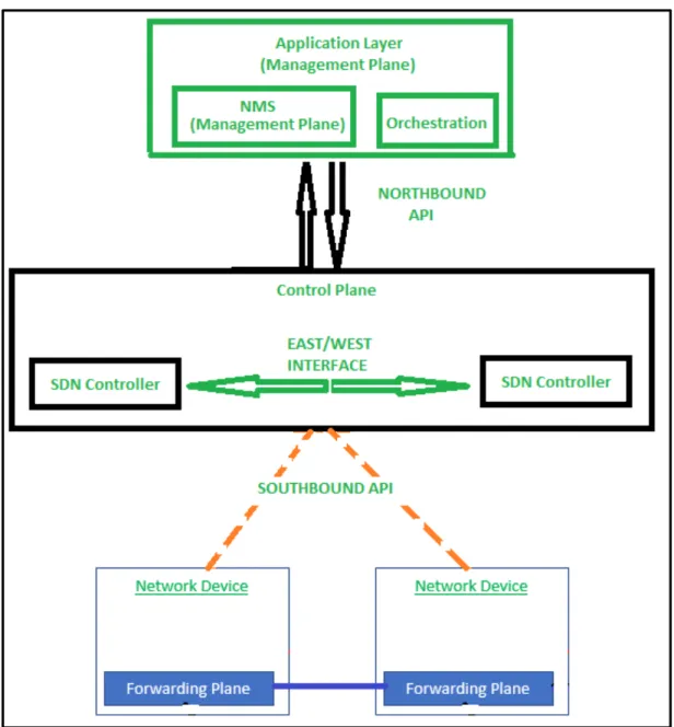
Open Networking Foundation (ONF) defines Software Defined Networking as the physical separation of the network control plane from the forwarding plane, whereby the control plane controls several devices externally [2]. It is an architecture that decouples the network control and forwarding functions. This creates a three-layer architecture as seen in Figure 2, which are infrastructure, control and application layers [2]. This allows the network to be dynamic, adaptable, cost-effective, software programmable and easily manageable [3]. OpenFlow was developed as the first standard communications interface defined between the control and forwarding planes of an SDN architecture [4].
20 © University of South Africa November 2018
1.4.1.2 Need for Software Defined Networking
Software Defined Networking makes it easier for network operators to evolve network capabilities. A single software program can control the behavior of the entire network [5]. This intelligence makes it possible to offer Networking-as-a-Service (NaaS). This significantly reduces expenses both Capital Expenditures (CAPEX) and Operational Expenses (OPEX) and enables fast service architecture. This is because the data plane is highly programmable from the remote-control plane at the controlling application [6]. Software Defined Networking also offers enhanced configuration, improved performance and encouraged innovation [7].
The high demand for data has affected the telecommunication industry, more specially the mobile network providers. This hunger for data is one of the catalysts for connectivity speeds of 5G networks. Service providers are facing challenges in complying with connectivity demands without substantial financial investments [8]. To address this issue, the industry had to look for initiatives aiming at cost reduction, increase of network scalability and service flexibility. The two networking architectures introduced to meet these requirements are Network Functions Virtualization and Software Defined Networking [9].
1.4.1.3 Software Defined Networking Architecture
The control plane is the centrally located control unit. It is called Software Defined Networking controller. It acts as the Network Operating Systems (NOS). The data plane resides inside the network core devices and is only responsible for forwarding data packets controlled by the central Software Defined Networking controller. These separated planes use protocols and an Application Programmable Interface (API) to communicate [10].
OpenFlow is one of the protocols used by Software defined networks and was started by Stanford University in 2008 [11]. Different companies came together in 2011 and formed Open Networking Foundation (ONF) to further develop OpenFlow and Software Defined Networking [12]. With the separation of the control and data planes, the data plane only performs the data packet forwarding action and it resides in the network device. The control plane is logically positioned on top of the
21 © University of South Africa November 2018
data plane and acts as the brains of the network [13].
Software Defined networks makes it possible to consolidate in one place complex software used to configure and control several devices making the process less expensive. A centralized controller gives a benefit of having a view of the network, which then enables it to make decisions on how data planes must move the traffic [14]. SDN makes it possible to dynamically provision the network. It improves network resources utilization and simplifies traffic engineering [15]. It makes it possible to use external applications to program the network. Communication between the devices in SDN uses open interfaces making it to be vendor neutral [16]. To test Software Defined Networks, an emulator called Mininet is amongst the popularly used tools [17].
1.4.1.4 Application Plane
Application Plane is logically on top of the Software Defined Networking architecture. It consists of applications and services that make requests for network functions from the Control Plane and the Data plane [18]. This can be any third-party application. Application layer through Software Defined Networking openness provides application developers with easy development and deployment of network applications. Application layer communicates with the controller layer using a Northbound Application Programming Interface (API).
1.4.1.5 Control Plane
Control Plane consists of control applications or programs. It operates on view of network and performs different functions like routing, traffic engineering, quality of service (QoS), security. Control plane has a global view of the network [19]. It performs configuration of each network device. Network Operating System (NOS) resides on the control plane. It is a distributed system that creates a consistent, updated network view and is executed as controllers in the network. The controller is responsible for making decisions on how packets should be forwarded. It does this by pushing flows instructions down to the network devices for execution. The control plane populates the forwarding tables that reside in the forwarding plane with flows based on the network topology
22 © University of South Africa November 2018
or external service requests.
1.4.1.6 Data Plane
Data Plane is responsible for handling data packets based on the instructions received from the controller. It is also known as forwarding plane. Forwarding decisions are flow-based. A flow in Software Defined Networking is a sequence of packets between a source and a destination. Flow decisions from the controller informs the data plane devices on how to process the packets [20]. Example of flow actions are forwarding, dropping and changing of packets. Data plane device are network devices like switches and routers.
1.4.2 Network Function Virtualization
Although Software Defined Networking is a complete standalone networking architecture, when used with Network Functions Virtualization, it provides end-to-end network automation. Software Defined Networking is classically defined as the separation of the control plane from the forwarding plane where the control plane is centralized while Network Functions Virtualization is the virtualization of services instead of using the hardware purposefully built to provide that service in a real-life network.
Network Functions Virtualization is a framework defined by the European Telecommunications Standards Institute (ETSI) that specifies the virtualization of various network services such as firewalls, load balancers and any other services typically associated with dedicated purpose-built hardware. In the telecommunication industry, NFV proposes to run the mobile network functions as software instances on commodity servers or datacenters, while SDN supports a decomposition of the mobile network into control-plane and data-plane functions. The combination of both SDN and NFV is considered as a very promising combination in achieving a cost-efficient mobile network architecture within the mobile network environment [21].
23 © University of South Africa November 2018
the transport network load overhead against several parameters such as data-plane delay, number of potential data centers and SDN control overhead. By moving network appliance functionality from proprietary hardware to software, Network Function Virtualization promises to bring the advantages of cloud computing to network packet processing [22]. It is for this reason that this paper looks to Mininet and its wireless extension Mininet-WiFi as the emulator, which can be used to emulate a Software Defined Network, intergraded on the network using a Network Virtualized Function (NVF) in the form of an application delivery (load balancer).
1.4.3 Mininet
1.4.3.1 Background
Recent Software-Defined Networking (SDN) approaches propose new means for network virtualization and programmability advancing the way networks can be designed and operated, including user-defined features and customized behavior at run-time [23]. The need for fault tolerance and scalability is leading to the development of distributed Software Defined Networking operating systems and applications. These developments and innovations call for an emulator, which will be able to produce reliable results when emulating such networks [24]. Mininet provides the platform to understand how actual Software Defined Networking works by creating a virtual network similar to the real network. This can be applied to run on small as well as very large-scale networks. One of the advantages of using Mininet is that, an application that works on it can be easily deployed to or integrated with a real network [25].
24 © University of South Africa November 2018
1.4.3.2 What is Mininet
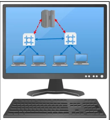
Mininet is the container-based emulator [26]. It allows the running of unmodified code interactively on virtual hardware on a regular computer. It provides convenience and realism at low cost compared to running on a hardware. Programs run on emulators require none or minimum modification when applied to real live networks [27]. Mininet runs unmodified code of network applications in lightweight Linux containers to achieve its scalability and accuracy. The greatest value of Mininet is supporting collaborative network research by enabling self-contained Software Defined Network prototypes, which anyone with a personal computer (PC) or laptop can download, and use [28] as seen in Figure 3. To achieve this, Mininet uses lightweight approach of OS-level virtualization features ranging from processes and network namespaces, which make it possible to scale to hundreds of nodes and represents a qualitative change in workflow through its ability to run and debug in real-time [29].
25 © University of South Africa November 2018
Among the main reasons for emulating a network is to be able to test and prove concepts. Current information on Software Defined Networking can be found in research papers and in white papers [30]. In the case that an organization, needs to prove these concepts or plans to deploy Software Defined Networks, the results can be easily reproduced. Mininet enables the implementation of virtual network systems, where an environment of virtual hosts, switches, and links runs on a modern multicore server, using real application and kernel code with software-emulated network elements. An experiment has been conducted using Mininet to reproduce key results from published network experiments such as DCTCP, Hedera, and router buffer sizing which were successfully reproduced highlighting another important ability of Mininet [31].
1.4.3.3 Advantages of using Mininet
Mininet is not the only simulator which can be used to simulate SDN networks. Other specialized hardware network devices require specialized programming languages [32] to run. Other notable simulators available include the used of Raspberry-Pi [33] to develop a cost-effective OpenFlow testbed for a small scale SDN networking and Fs-SDN [34]. Although some of these other simulators do have advantages over Mininet on some aspects of simulation [35], Mininet remains the simulator of choice for SDN networks due to its flexibility and many advantages. Other simulators use full system virtualization, heavyweight containers with increasing complexity and overheads while decreasing usability. Mininet support the development of SDN systems and applications reliably without access to an expensive testbed [36].
Networks emulated in Mininet have produced reliable results, which has made Mininet to be used as a reference system when other emulators like Fs-SDN were being developed or tested. Fs-SDN is a Python-based tool developed for generating network flows records and interface counters. To evaluate Fs-SDN accuracy, scalability, and speed, a side by side setting up between Fs-SDN and Mininet was done with a series of identical network and traffic configurations. After which network traffic and system-level measurements where compared between the two. In this investigation, Mininet was discovered to be a better tool.
26 © University of South Africa November 2018
Mininet supports OpenFlow-based Software-defined Networking (SDN). It provides a flexible and cost-efficient experimental platform to develop, test, and evaluate OpenFlow applications. In Mininet, the processes of the virtual hosts and their application processes run inside the
container. This allows them to have an independent view of system resources but still share the kernel with other containers [37].
1.4.3.4 Mininet Installation
Mininet can be installed in three (3) different ways. The first one which is the easiest way is to download a pre-packed Mininet Virtual Machine (VM). The pre-packed Mininet Virtual Machine (VM) comes with Mininet and all required OpenFlow binaries and tools already pre-installed. A complete, compressed Mininet VM is about 1GB and can be used in most common hyper visors such as VMware, Xen and VirtualBox. The second option is to natively install Mininet from source. This option is suitable for local Virtual Machines and remote or cloud storage. The third option is to install Mininet from packages. This option may give an older version of Mininet and would require an upgrade once the installation has been completed. The latest Mininet release as of August 2018 is Mininet 2.2.2.
1.4.3.5 How does Mininet work
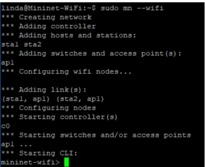
Mininet network is made of isolated hosts, which are a group of user-level processes moved into a network namespace that provide exclusive ownership of interfaces, ports and routing tables. The emulated links uses Linux Traffic Control (tc) which enforces the data rate of each link to shape traffic to a configured rate. Each emulated host has its own virtual Ethernet interface(s). The emulated switches are Open virtual Switches (OvSwitch) running in kernel mode or default Linux Bridge. These devices can run in ether kernel or user space to switch packets across interfaces. The process and code for creating a simple wireless network in Mininet is shown in Figure 4.
27 © University of South Africa November 2018
Figure 4. Basic wireless network created in Mininet
The study by Keti and Askar in [38] highlights Mininet’s characteristics as being flexible, applicable, intractable, scalable, realistic and share-able. This is because in Mininet, new topologies and new features can be set in software using programming languages and common operating systems. Networks emulated in Mininet are usable with real life networks based on hardware without the need to make changes in source codes. To manage and run the simulated network in Mininet occurs in real time as it happens in a real-life network. Mininet can be scaled to large networks with hundreds or thousands of nodes. Networks implemented on Mininet can be easily shared, as it is share-able [39].
Software Defined Networking switches, hosts, controllers and links can be created by typing commands through Mininet’s command line interface. The command line interface (CLI) in Mininet supports most Linux commands. The most commonly used commands are-: nodes: which lists all created nodes, dump: which displays the information about the network and created nodes, net: which shows how network elements are connected to each other.
28 © University of South Africa November 2018
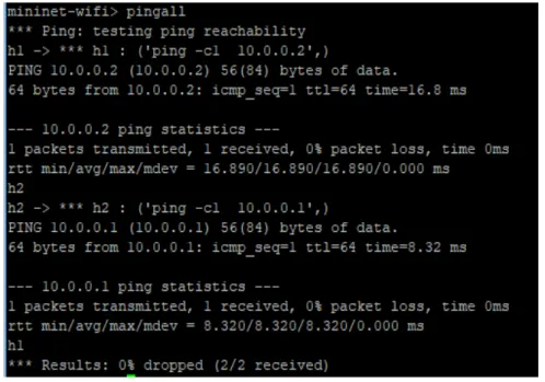
The command line interface (CLI) also supports the day-to-day troubleshooting commands used in computer networking. These commands include “pingall”, which output the results of the connectivity test among all nodes as seen in Figure 5. “Ifconfig” is also supported which displays the internet protocol (IP) information of the node. “Iperf” is also supported which is a tool used to test network performance. Iperf uses a client/server model, where traffic is initiated from the client and traverses the network to the server. “Iperf” creates data test streams supported by the network with a time-stamp and report the amount of data transferred and the throughput measured.
Figure 5. Execution of “pingall” command
“Iperf” supports two types of transport protocols: Transmission Control Protocol (TCP)andUser Datagram Protocol (UDP). Many applications like File Transfer Program (FTP), Simple Mail Transfer Protocol (SMTP) and Hypertext Transfer Protocol (HTTP) use TCP as the transport protocol. Using TCP mode, “Iperf” tests the maximum TCP bandwidth at the transport layer. In UDP mode, “Iperf” tests the jitter, packet loss and bandwidth. UDP mode is ideally for testing quality of service for applications like voice and video streaming. To see the list of all available commands, one can use “help” command, which is also supported in Mininet [40].
29 © University of South Africa November 2018
1.4.3.6 Mininet Topologies
Mininet supports five built-in network topologies. These built-in topologies are Minimal, Single, Linear, Tree and Reversed. Network topologies in Mininet can be modified using the command-line interface (CLI) [41]. The default topology is the minimal topology, which includes one OpenFlow kernel switch connected to two hosts, plus the OpenFlow reference controller.
• Minimal Topology: Minimal is the basic topology with one switch and two hosts.
• Single Topology: Single switch connected to k hosts where k is the number of hosts.
• Linear Topology: In Mininet, linear topology support k switches with k hosts where each host connects to one switch and all switches connects in a line. Linear topology can be created using “sudo mn -topo linear, k” where k is the number of host and switches.
• Tree Topology: This is a topology for a tree network with a given depth and fanout. This is a multilevel topology, which adds a subtree starting with node n.
• Reversed Topology: Reverse topology is the single switch connected to k hosts, with reversed ports where k is the number of hosts. The lowest-numbered host is connected to the highest-numbered port. Useful to verify that Mininet properly handles custom port numberings.
1.4.3.7 Mininet Python Script
Mininet Python Application Programming Interface (API) can also be used to create custom network topologies [44]. Python is an interpreted, interactive, object-oriented programming language. It provides high-level data structures. Python is modular by nature. The kernel is very small and can be extended by importing extension modules. A python program is compiled automatically by the interpreter and can be installed in any computer running any operating system [45]. The main classes used in Mininet Python script are mininet (net), link, node and topo. The complete list of classes includes clean, cli, log, nodelib, and topolib.
30 © University of South Africa November 2018
The Net class provides network emulation with hosts spawned in the namespace. This class has the following methods-:
• addHost (): This method adds a host to the network.
• addSwitch (): This method adds a switch to the network.
• addLink (): This method links two nodes together.
• addController (): This method adds a controller to the network
• getNodeByName (): This method return node with given name
• start (): This method starts the controller, switches and hosts
• stop (): This method stops the controller, switches and hosts
• ping (): This method ping between all specified hosts and return all data.
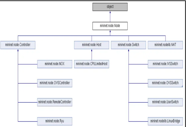
The Node class provides a virtual network node in a network namespace. In Mininet, a node can be either a host, switch or the controller. A host is a simple network node used to emulate the end computer or server.A switch is a node that is running an OpenFlow switch. The supported switches subclasses are OVSBridge, which is the Open Virtual switch in standalone or bridge mode. OVSKernelSwitch, which is the Open Virtual Switch that run-in kernel space. UserSwitch, which is the Open Virtual Switch that runs in user space and is slower that the OVSKernelSwitch and LinuxBridge, which is a normal Linux bridge. A Controller is a Node that is running an OpenFlow controller. Mininet support NOX, OVSController, RemoteController, Ryu subclasses for creating a controller.
The node class in Mininet supports the following methods-:
• MAC/setMAC: This method returns/assign the MAC address of a node or specific interface.
• IP/setIP: This method returns/assign IP address of a node or specific interface
• cmd: This method sends a command then waits for an output and return in.
31 © University of South Africa November 2018
The link class provides a basic link, which is represented as a pair of nodes. This class uses a link method, which creates a link to another node and makes two new interfaces. Node class
inheritance diagram is shown in Figure 6.
Figure 6. Mininet NODE class
The topo class provides the data center network representation for structured multi-trees. This class uses the following methods-:
• Methods similar to net e.g addHost, addSwitch, addLink
• addNode: This method adds nodes to the graph
• addPort: This method generates port mapping for new edge
• switches: This method return all switches
• hosts/nodes/switches/links: return all hosts
32 © University of South Africa November 2018
1.4.4 Mininet-WiFi
Mininet can also be used to emulate Software Defined Wireless Networks. To achieve this, the base code of Mininet must be extended by modifying classes and scripts to support wireless functionalities while also keeping all Software Defined Networking capabilities from the standard Mininet network emulator. Mininet-Wi-Fi is a fork of Mininet emulator, which extends its functionality by adding virtualized Wi-Fi stations and access points based on the standard Linux wireless drivers and the 802.11_hwsim wireless simulation driver. It adds classes to support the addition of wireless devices in a Mininet network scenario and to emulate the attributes of a mobile station such as position and movement relative to the access points. The 802.11 is the wireless standard by Institute of Electrical and Electronics (IEEE), which provides specifications for implementing wireless communications using the Wi-Fi (Wireless Fidelity) [42].
Mininet-WiFi developers have showcased it in a scenario with ad hoc and infrastructure wireless modes using a single experimental platform integrating virtual and physical nodes. This demonstration featured Mininet-WiFi as an emulator with the ability to run realistic experiments in hybrid physical-virtual environments, where users were able to experience it first hand by connecting their devices and interacting with virtual Wi-Fi stations in a wireless mesh network. They were able to connect to the internet through the emulated Software Defined Wireless Network infrastructure. Mininet-WiFi enhances Mininet emulator with virtual wireless stations and access points while keeping the original SDN capabilities and the lightweight virtualization software architecture [43].
1.4.5 Other Related Work
One of the latest studies which has been conducted is the performance of the three controllers named, Open Network Operating System (ONOS) [46], OpenMUL [47] and POX [48]. This was done by implementing the topology in Mininet and analysing real packet-in /packet-out messages between the data and control plane [49]. ONOS is a Java-based controller while POX is a
python-33 © University of South Africa November 2018
based centralised controller and OpenMUL is a centralised controller based on C programming language. Mininet and OpenvSwitch were used to create a linear topology and each switch in the topology was connected to a host. The performance of the controllers were then compared and measured using Mininet-Wireshark packet analysis and also Cbench which is a benchmarking tool that uses fake control packets generated from switch instances. This study showed that using Cbench [50] greatly under-estimates the performance by up to 96% for controller latency and 98% for controller throughput.
Mininet and OpenDaylight were suitable tools to conduct scalability analysis and flow admission in a Software Defined Network [51]. This study goes into length in explaining why these tools were suitable to conduct the study. Among the things mentioned is that Mininet is freely available and has already built in Open-Flow switches and virtual controllers [52]. It is also effortless because of easily building topology via drag and drop capability. Using OpenDaylight helped with flow performance and overall network scalability study [53]. Their conclusion state that the performance of the tool is strongly devoted to real environment results. During this study, they also observed the effectiveness of Mininet especially on time and resources according to prototyping, deployment and sharing.
Another groundbreaking implementation of Software Defined Networking using Mininet and OpenDaylight controller is the one that was done in the study to develop a resilient network between Philippines and Vietnam [54]. The aim of the study was to integrate Internet of Things (IoT) application (temperature and humidity sensor) applied to Software Defined Network using Mininet and OpenDaylight controller between Mapua University in Philippines and Vietnam National University in Vietnam. Data from the temperature and humidity sensors was successfully passed through the Software Defined Network having OpenFlows as it routing protocol. The results from this study also shows that Software Defined Networks has better latency, packet loss, bandwidth and convergence time compared to traditional network.
34 © University of South Africa November 2018
CHAPTER 2
2.1 Methodology
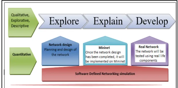
The design of this study is a combination of qualitative, explorative, descriptive and quantitative design as shown in Figure 7. The purpose of its combination is to gain a richer understanding of the existing studies and the findings. The presentation will be of a descriptive nature. The purpose of the quantitative nature is to get a deeper understanding of the network design and show the results on the first-hand bases through emulation of a network.
Figure 7. Methodology framework
35 © University of South Africa November 2018
2.1.1 Logical Network
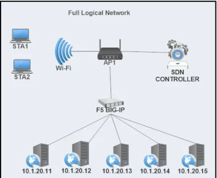
This project is based on simulating a Software Defined Network using Mininet, which communicates with the virtualized network hosted on the Emulated Virtual Environment – Next Generation (EVE-NG) which is a software that provides tools to model virtual devices and interconnect them with other virtual or physical devices.The OpenDaylight controller used in this study is hosted on Amazon Web Services (AWS) cloud platform. The logical network consists of a website hosted on the LAMP (Linux, Apache, MySQL, PHP) virtual machine. The F5 application delivery controller (ADC) provide load balancing of requests sent to the web applications. The LAMP server and the F5 application delivery controller are hosted on EVE-NG. Two logical networks were used in this study to test different scenarios. The first scenario emulated a wireless Software Defined Network while the second scenario emulated the wired Software Defined Network. Mininet-WiFi was used to emulate wireless Software Defined Network. These network configurations were selected based on the industy best practice of Software Defined Networking. The logical network used to test wireless Software Defined Network is seen in Figure 8. Figure 9 shows the logical network used to test wired Software Defined Network.
36 © University of South Africa November 2018
Figure 8. Logical network to test wireless SDN
37 © University of South Africa November 2018
2.1.2 Virtualized network on EVE-NG (Emulated Virtual Environment – Next
Generation)
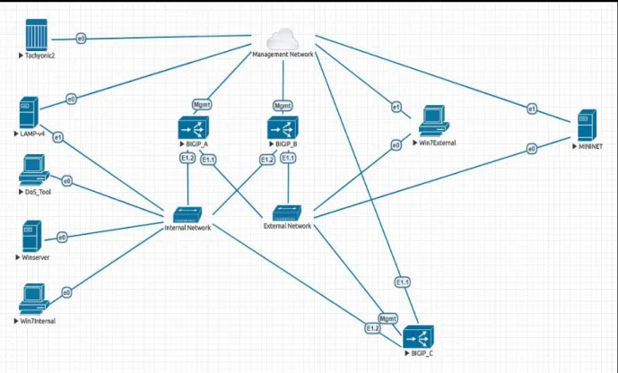
EVE-NG is the Emulated Virtual Environment software as can be seen in Figure 10 used for Network, Security and DevOps professionals and to implement the real life network. It provides tools to be able to model virtual devices and interconnect them with other virtual or physical devices. It can be used in many ways, but it is mostly commonly used for testing modern technologies like network automation, proof of concepts (POC), network troubleshooting, test software in a simulated network, test out security vulnerabilities of any kind, system engineering etc.
The network part used in this project which is on EVE-NG is the network used on daily basis to test networks and application solutions, perform proof of concepts, network designs and troubleshooting. Some of the network devices seen in Figure 10 like the DoS_Tool, Winserver, Win7internal, Win7external and Tachyonic2 had no role in this project. The aim of using this already existing network topology was to test if indeed Mininet can be integrated and form part of the already existing real-life network that was built to perform other tasks not only for testing Software Defined Networking.
2.1.3 LAMP Server
LAMP is a group of open source software used to setup and run webservers. This is an acronym that stands for Linux, Apache, MySQL, and PHP. In this case, it uses Linux as the operating system, Apache as the Web server, MySQL as the relational database management system and PHP as the object-oriented scripting language. LAMP is mostly referred to as a LAMP stack because it has four layers. This stack can be built on different operating systems and the acronym changes to reflect that operating system. For example, when used with the Windows operating system, it is called WAMP; with Macintosh operating system, it is called MAMP; and with a Solaris system, it is called SAMP.
38 © University of South Africa November 2018
Figure 10. Network on EVE-NG
Five (5) servers were created on LAMP virtual machine as seen in Figure 10. Each of these servers hosted a test website. This is the typical scenario used by companies to host their applications. Same applications are hosted on different servers so that the servers can share the load as well as to offer backup and redundancy. Using LAMP, many applications can be hosted on one machine as if they were hosted on different machines. For this project, LAMP was used to test if hosts created on Mininet will be able to access websites hosted on it.
The configured servers were from server 1 to server 5 with Internet Protocol (IP) addresses 10.1.20.11 up to 10.1.20.15. All these configured servers deliver the same web application. The web application hosted by these servers is the same application that is used by the F5 Company which has most features used by companies in their applications. The configuration of these servers is not part of the scope for this project. This is because they are configured to do more than what is required for this project as this is a network used for many scenarios for real network environments.
39 © University of South Africa November 2018
2.1.4 F5 BIG-IP Virtual Edition (VE)
F5 is a company that specializes in application delivery networking (ADN) technology. The company name F5 was inspired by the 1996 movie Twister in which reference was made to the fastest and most powerful tornado on the Fujita Scale: F5. The company F5 founders believed that this company will cause the most powerful change in the networking field. F5 is involved in the delivery of web applications, security, performance, availability of servers, data storage devices, and other network and cloud resources. To do this, F5 uses BIG-IP platform, which is a blend of software and hardware that perform the function of a load balancer and a full proxy. BIG-IP is not an acronym for anything either, F5 got the concept from TCP/IP (Transmission Control Protocol/ Internet Protocol) notation. The BIG part of the name is from F5 view of this technology as being a full proxy, which presents a virtual IP on behalf of many devices that are behind it. This makes it according to F5 an IP bigger that a normal IP address, hence it is called BIG-IP.
BIG-IP gives the ability to control the traffic that passes through the network. These devices come in two (2) flavors, which are physical hardware and virtual Edition (VE). The virtual editions of BIG-IP products offer the same variety of features available in hardware solutions and can be deployed on a public or private cloud. Virtual Edition is the flavor of BIG-IP application delivery controller used in this project.
Three devices (BIGIP_A, BIGIP_B, and BIGIP_C) were installed and Local Traffic Manager (LTM) module was provisioned. The Local Traffic Manager (LTM) module is BIG-IP load balancer module. The devices are configured in a High Availability (HA) mode. This means that when one device fails, the other devices would take over and process the traffic that was being process by the failed device. The configured network on the devices include the internal VLAN (Virtual Local Area Network), which is the network part that communicates with backend servers running on the LAMP stack and the external VLAN (Virtual Local Area Network). The external VLAN is the network part that communicates with the company external network. Mininet used this external virtual local area network to communicate with web applications via the BIG-IP application delivery controller.
40 © University of South Africa November 2018
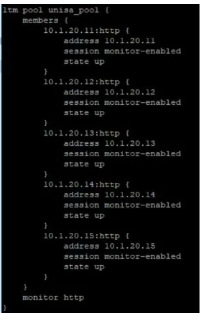
In the BIG-IP application controller, a virtual server called “unisa_vs” was created and configured as seen in Figure 11. Health monitor was enabled to check the status of the servers in the LAMP virtual machine as seen in Figure 12. This virtual sever listen to incoming traffic from the external virtual local area network. The pool of servers called “unisa_pool” was also created as seen in Figure 13. This pool points to the backend servers, which are configured on the LAMP server. These servers were enabled to listen for hypertext transmission protocol (http) port 80 requests, which is the port for web services. The “unisa_vs” virtual server uses the round-robin algorithm to load balance the requests. In round-robin algorithm, all requests are evenly distributed across pool members. In this case the 1st request goes to 1st node, 2nd request to 2nd node and 3rd to 3rd
node, 4th request to 4th node, 5th request to 5th node and 6th request to 1st node and continue in that
sequence through all five configured nodes.
Figure 11. Virtual server configuration
41 © University of South Africa November 2018
Figure 13. Pool configuration
These configured Local Traffic Manager (LTM) components works as follows-:
• The monitor keeps on monitoring the status of the nodes in the LAMP and return a green circle is the node is up as seen in Figure 14.
• The virtual server listens for incoming traffic on port 80 of 10.1.10.20 and use round-robin algorithm to load balance the traffic to the nodes on the pool.
• The pool contains the list of nodes which servers the same web application.
42 © University of South Africa November 2018
2.1.5 Listening tools to network parameters
Wireshark is the packet monitoring and analyzing tool that provides the ability to analyze data traffic interactively on a network. Wireshark display packets with detailed protocol information. It can be used to analyze different types of traffic in all layers of the Open Systems Interconnection (OSI). Wireshark puts the network card into promiscuous mode (a mode that tells it to read all packets sent to it) and uses PCAP (packet capture) which consists of an application programming interface for capturing network traffic. From the captured packets, Wireshark then generates many reports such as round-trip time, throughput, flow graph and many more reports of Open Systems Interconnection protocol. Wireshark supports several plugins which can be enabled to give it more capabilities. One of such plugins is Transum.
Transum is a Wireshark plug-in for dynamically calculating various response time latencies within sessions. It uses Response Time Element (RTE) model to provide a breakdown of the overall response time for a service. Transum’s application messages are called Application Protocol Data Units (APDU). APDU is the flow between the client and services. APDU response time is the total time the user must wait for a completion of a request. Service time is the time it takes for the service to process the request. Request spread is the time needed to transmit the whole request from the client to the service. Response spread is the time transmit the whole response from the service to the client.
Transum is an ideal tool for troubleshooting latency on the multi-tiered networks. The example of such networks is Client -->Webserver --> Database services. When an application is experiencing an overall high latency issue, using Transum can help in identifying the part of the service that is responsible for the high latency issue. This is done by first running packet capture with Transum enable between the client and the webserver, and then between the webserver and the Database. By comparing the overall service latency against the two run Transum captures, the part responsible for the latency can then be easily identified. For this project, since the topology was just client --> Webserver, Transum only produced one Response Time Element data with the service time equal to the APDU response time. For this reason, Transum capture was not included on the result section of this project.
43 © University of South Africa November 2018
2.1.6 Wireless Software Defined Network on Mininet-WiFi
A Mininet-WiFi virtual machine was created by installing Mininet-WiFi on an Ubuntu Server virtual machine. Two (2) network interfaces were configured and associated with Mininet-WiFi virtual machine (VM). The first attached network interface was a host-only adapter. This allows host computer to be able to connect to the virtual box using terminal emulator. The terminal emulator such as Putty offers better command line interface as compared to Mininet command prompt. The second network interface that was attached was the Network Address Translation (NAT) adaptor. This is the connection that Mininet use to communicate with the external networks. Mininet-WiFi basic network topology was used which consist of a wireless access point (AP1) with two wireless stations (Sta1, Sta2) and the Mininet Software Defined Networking controller. The access point connected to the controller (C0) using a virtual connection and the two (2) stations are attached to the access point (AP) using the simulated wireless interface. Once the basic network was created, the external Virtual Local Area Network interface was then added to the access point (AP) interface using OpenFlow commands as seen in Figure 15. Both stations (Sta1 and Sta2) internet protocol (IP) addresses were modified such that they are also on the same external VLAN subnet.
44 © University of South Africa November 2018
The logical emulated wireless Software in Mininet-WiFi can be seen in Figure 16 below.
Figure 16. Logical Mininet-WiFi network
2.1.7 Wired Software Defined Network on Mininet
The Mininet Virtual Machine (VM) used in this paper is hosted on Oracles’ Virtual Box. Mininet was installed on Ubuntu 17 operating system. The emulated Software Defined Network in Mininet was created using a Python script to enable communication with the controller using the Application Programmable Interface (API). Application program interface (API) is a set of routines, protocols, and tools for building software applications. It specifies how software components should interact. They are used when programming graphical user interface (GUI) components. API makes it easier to develop a program by providing all the building blocks. One of the commonly used API in the field of networking is REST API.
45 © University of South Africa November 2018
communication used in the development of Web Services. It enables users to connect and interact with cloud services efficiently. To test the API, the program called “Postman” can be used. “Postman” is an application for testing APIs by sending request to the web server and getting the response back. “Postman” makes it easy to test, develop and document APIs. It allows users to set up all the headers and cookies the API expects and checks the response. “Postman” was used to send RESTCONF GET API to retrieve node inventory and topology as created by Mininet and seen by OpenDaylight controller as seen in Figure 17 below.
Figure 17. Postman "GET" node inventory API
For the Mininet script to work, three (3) main Mininet API classes were used. Those classes are Topo, Switch and Controller.
A function, which is used to create a custom network was created using Python. For this function to create the network, Mininet was prevented from creating the network using the default values. This was achieved by setting the topo class to none and the build class to false. Using the controller class, a remote controller was defined and given values for the name and an IP address, which in this case is the IP address of the OpenDaylight controller hosted on Amazon cloud. The connection port was set to port 6633.
46 © University of South Africa November 2018
hosts were also defined and given networking properties. The script defines the network subnet that the controller must use together with the links between the switch and the hosts. As part of the program, the script programs the controller to add the external interface to the switch after creating the network. This interface is used by Mininet to reach the Linux server inside the company domain.
To start the program, we loaded the saved python script from the directory that it was saved on. Mininet created the network as defined by the script. The created network consists of two (2) hosts and the Open Virtual Switch (OVS). The created switch has a control channel, which it uses to communicate with the controller. It has the pipeline, which consists of flow tables. There is also data path, which is the forwarding plane as seen in Figure 18.
Figure 18. OpenFlow virtual Switch (OvSwitch)
2.1.8 OpenDaylight controller
Mininet support extensible Python API for network creation and experimentation. Depending on the choice of the controller used, Mininet also supports programs written in C, JAVA and C++. In this project the network is created on Python which is the interpreted high-level programming language for general purpose programming and the controller used on this project is the OpenDaylight controller. OpenDaylight (ODL) is a modular open platform for customizing and automating networks of any size and scale. It is created and managed by OpenDaylight Foundation as part of the Linux foundation project.
47 © University of South Africa November 2018
It is based on Services Abstraction Layer (SAL), which allows it to support other protocols and not only OpenFlow. It is implemented in Java and can be deployed in any system supporting Java. OpenDaylight controller was developed by the OpenDaylight consortium in 2013. OpenDaylight project is supported by Cisco, Juniper, VMWare and many other vendors and companies operating in the networking environment. This support by many organizations enables OpenDaylight to be vendor neutral [55].
The controller uses Application Programmable Interfaces (API) like Representational State Transfer (REST) technology to communicate with the Network Applications orchestrations and services layer. This can include OpenStack Neutron, Virtual Tenants Network (VTN) coordinator [56-57]. The controller layer itself run several services which includes service abstraction layer (SAL), OpenStack service, base network service and many more. To communicate with data plane elements, the controller uses southbound interfaces and protocol plugins such as OpenFlow, the Open vSwitch Database Management Protocol (OVSDB) [58], the Network Configuration Protocol (NETCONF) [59] and many more [60].
48 © University of South Africa November 2018
The OpenDaylight controller architecture is shown on Figure 19 below.
Figure 19. OpenDayligh controller architecture
In this project we used the eighth release of the OpenDaylight controller, which is called Oxygen. We downloaded the software from the OpenDaylight software download page and installed the controller on the Ubuntu 17 server. To install and enable required features that the OpenDaylight controller must use, an open source application called Apache Karaf is used. Karaf as it is normally called is a modular Open Services Gateway Initiative (OSGI) that provides tools and features required to deploy an application. An Open Services Gateway Initiative (OSGI) is a set of specifications for developing and deploying modular software programs and libraries, which are packed in bundles. Karaf enables modules to be installed, started, stopped, updated, and uninstalled without requiring a reboot.
49 © University of South Africa November 2018
By default, the OpenDaylight controller has no features enabled. We have installed and enabled the following features in this project on the controller (but there are many features, which can be installed and enabled)-:
• odl-restconf – Representational State (REST) like protocol that provides a programmatic interface over Hyper Text Transfer Protocol (HTTP) for accessing data on port 8080 for HTTP requests.
• odl-l2switch-all – Layer2 switch functionality.
• odl-mdsal-apidocs - Model Driven Service Abstraction Layer (MD-SAL) Application Programmable Interface (API) Documentation.
• odl-dlux-all - Graphical user interface for OpenDaylight based on the AngularJS Framework.
The OpenDaylight controller used on this project is hosted on Amazon Web Services (AWS) cloud platform. We have used the Elastic Compute Cloud (EC2), which is a secure and resizable compute node. It allowed us to obtain and configure capacity in minutes. The Elastic Compute Cloud (EC2) can scale both up and down allowing us to increase or decrease capacity as per our need. Wireshark, the network packet analyzer was used to analyze communication between the Open Virtual Switch in Mininet and the OpenDaylight controller.
When the communication between the switch and the controller is established. The controller adds flows to enable the switch to behave like a learning switch. When the switch receives a packet, it starts by performing a table lookup in the first flow table called table 0. In pipeline, each flow table contains one or more flow entries. Matching starts with the first flow table. If a Match is found, instructions associated with flow entry are executed. Instruction may direct the packet to next flow table in pipeline. When processing stops, the associated action set is applied, and packet forwarded. Instructions describe packet forwarding, packet modification, group table processing and pipeline processing. The summary flow chart is shown in Figure 20. This flow chart represents the program used to program the controller to establish communication between the controller in the cloud and the switch within Mininet.
50 © University of South Africa November 2018
51 © University of South Africa November 2018
CHAPTER 3
3.1 Implementation of Mininet emulated network
To demonstrate that the network emulated on Mininet can be deployed in real life, the wired Mininet network seen on Figure 21 was deployed.
52 © University o