Enhancing network robustness using software-defined networking
by
Xin Li
B.S., Beihang University (Beijing University of Aeronautics and
Astronautics), China, 2012
AN ABSTRACT OF A DISSERTATION
submitted in partial fulfillment of the
requirements for the degree
DOCTOR OF PHILOSOPHY
Department of Electrical and Computer Engineering
College of Engineering
KANSAS STATE UNIVERSITY
Manhattan, Kansas
Abstract
As today’s networks are no longer individual networks, networks are less robust towards failures and attacks. For example, computer networks and power networks are interdepen-dent. Computer networks provide smart control for power networks, while power networks provide power supply. Localized network failures and attacks are amplified and exacerbated back and forth between two networks due to their interdependencies. This dissertation focuses on finding solutions to enhance network robustness. Software-defined networking provides a programmable architecture, which can dynamically adapt to any changes and can reduce the complexities of network traffic management. This architecture brings oppor-tunities to enhance network robustness, for example, adapting to network changes, routing traffic bypassing malfunction devices, dropping malicious flows, etc. However, as SDN is rapidly proceeding from vision to reality, the SDN architecture itself might be exposed to some robustness threats. Especially, the SDN control plane is tremendously attractive to attackers, since it is the “brain” of entire networks. Thus, researching on network robustness helps protect network from a destructive disaster.
In this dissertation, we first build a novel, realistic interdependent network framework to model cyber-physical networks. We allocate dependency links under a limited budget and evaluate network robustness. We further revise a network flow algorithm and find solutions to obtain a basic robust network structure. Extensive simulations on random networks and real networks show that our deployment method produces topologies that are more robust than the ones obtained by other deployment techniques.
Second, we tackle middlebox chain problems using SDN. In computer networks, applica-tions require traffic to sequence through multiple types of middleboxes to accomplish network functionality. Middlebox policies, numerous applications’ requirements, and resource alloca-tions complicate network management. Furthermore, middlebox failures can affect network
robustness. We formulate a mixed-integer linear programming problem to achieve a network load-balancing objective in the context of middlebox policy chain routing. Our global rout-ing approach manages network resources efficiently by simplifyrout-ing candidate-path selections, balancing the entire network and using the simulated annealing algorithm. Moreover, in case of middlebox failures, we design a fast rerouting mechanism by exploiting the remaining link and middlebox resources locally. We implement proposed routing approaches on a Mininet testbed and evaluate experiments’ scalability, assessing the effectiveness of the approaches.
Third, we build an adversary model to describe in detail how to launch distributed denial of service (DDoS) attacks to overwhelm the SDN controller. Then we discuss possible defense mechanisms to protect the controller from DDoS attacks. We implement a successful DDoS attack and our defense mechanism on the Mininet testbed to demonstrate its feasibility in the real world.
In summary, we vertically dive into enhancing network robustness by constructing a topological framework, making routing decisions, and protecting the SDN controller.
Enhancing network robustness using software-defined networking
by
Xin Li
B.S., Beihang University (Beijing University of Aeronautics and
Astronautics), China, 2012
A DISSERTATION
submitted in partial fulfillment of the
requirements for the degree
DOCTOR OF PHILOSOPHY
Department of Electrical and Computer Engineering
College of Engineering
KANSAS STATE UNIVERSITY
Manhattan, Kansas
2017
Approved by: Co-Major Professor Caterina Scoglio Approved by: Co-Major Professor Don GruenbacherCopyright
c
Abstract
As today’s networks are no longer individual networks, networks are less robust towards failures and attacks. For example, computer networks and power networks are interdepen-dent. Computer networks provide smart control for power networks, while power networks provide power supply. Localized network failures and attacks are amplified and exacerbated back and forth between two networks due to their interdependencies. This dissertation focuses on finding solutions to enhance network robustness. Software-defined networking provides a programmable architecture, which can dynamically adapt to any changes and can reduce the complexities of network traffic management. This architecture brings oppor-tunities to enhance network robustness, for example, adapting to network changes, routing traffic bypassing malfunction devices, dropping malicious flows, etc. However, as SDN is rapidly proceeding from vision to reality, the SDN architecture itself might be exposed to some robustness threats. Especially, the SDN control plane is tremendously attractive to attackers, since it is the “brain” of entire networks. Thus, researching on network robustness helps protect network from a destructive disaster.
In this dissertation, we first build a novel, realistic interdependent network framework to model cyber-physical networks. We allocate dependency links under a limited budget and evaluate network robustness. We further revise a network flow algorithm and find solutions to obtain a basic robust network structure. Extensive simulations on random networks and real networks show that our deployment method produces topologies that are more robust than the ones obtained by other deployment techniques.
Second, we tackle middlebox chain problems using SDN. In computer networks, applica-tions require traffic to sequence through multiple types of middleboxes to accomplish network functionality. Middlebox policies, numerous applications’ requirements, and resource alloca-tions complicate network management. Furthermore, middlebox failures can affect network
robustness. We formulate a mixed-integer linear programming problem to achieve a network load-balancing objective in the context of middlebox policy chain routing. Our global rout-ing approach manages network resources efficiently by simplifyrout-ing candidate-path selections, balancing the entire network and using the simulated annealing algorithm. Moreover, in case of middlebox failures, we design a fast rerouting mechanism by exploiting the remaining link and middlebox resources locally. We implement proposed routing approaches on a Mininet testbed and evaluate experiments’ scalability, assessing the effectiveness of the approaches.
Third, we build an adversary model to describe in detail how to launch distributed denial of service (DDoS) attacks to overwhelm the SDN controller. Then we discuss possible defense mechanisms to protect the controller from DDoS attacks. We implement a successful DDoS attack and our defense mechanism on the Mininet testbed to demonstrate its feasibility in the real world.
In summary, we vertically dive into enhancing network robustness by constructing a topological framework, making routing decisions, and protecting the SDN controller.
Table of Contents
List of Figures . . . xii
List of Tables . . . xv
Acknowledgements . . . xv
Dedication . . . xvi
Preface . . . xvii
1 Introduction and background . . . 1
1.1 Introduction and motivation . . . 1
1.2 Background . . . 4 1.2.1 Network robustness . . . 4 1.2.2 Software-defined networking . . . 5 1.2.3 OpenFlow . . . 7 1.2.4 Middlebox . . . 9 1.3 Contributions . . . 11 1.4 Organization . . . 12 2 Literature review . . . 13
3 Robust network framework . . . 19
3.1 Interdependent network model . . . 20
3.1.1 Classic interdependent network model . . . 20
3.1.3 Cascading failures . . . 21
3.1.4 Individual network model . . . 23
3.1.5 Discussion of dependency links . . . 24
3.2 Dependency-link allocation . . . 24
3.2.1 Problem formulation . . . 24
3.2.2 Existing tools limitation . . . 25
3.3 Revised network flow algorithm . . . 25
3.3.1 Notations of cost flow . . . 25
3.3.2 Basic constraints in cost flow . . . 26
3.3.3 Algorithm process . . . 26
3.3.4 Relationship between flow graph and link selection . . . 28
3.4 Dependency-link allocation example under limited budget . . . 30
3.4.1 Parameters of the example . . . 30
3.4.2 Adding non-weighted links . . . 31
3.4.3 Adding weighted links . . . 31
3.5 Non-weighted dependency-link model simulation and comparison . . . 31
3.6 Weighted dependency-link model simulation and comparison . . . 32
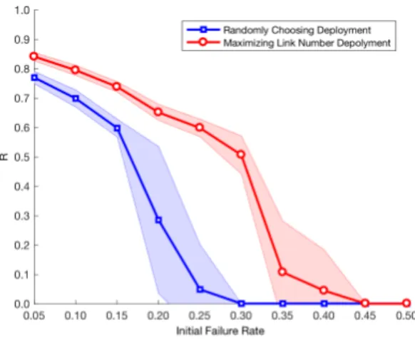
3.6.1 Maximizing the number of dependency links . . . 34
3.6.2 Randomly choosing dependency links . . . 34
3.6.3 Comparison . . . 36
3.7 Extensive simulations on real network topologies and Barab´asi-Albert networks 38 3.7.1 Real network topology simulation and comparison . . . 38
3.7.2 Dependency-link allocation on Barab´asi-Albert networks . . . 39
3.8 Contributions . . . 40
4 Middlebox policy enforcement using SDN . . . 42
4.1 Middlebox policy enforcement problem . . . 43
4.1.2 Candidate paths generation . . . 43
4.2 Global load-balancing routing . . . 45
4.2.1 Notations . . . 46
4.2.2 Formulations . . . 46
4.2.3 Other use cases . . . 48
4.2.4 Complexity analysis . . . 49
4.3 Solutions of the global load-balancing routing . . . 49
4.3.1 Branch-and-bound algorithm . . . 50
4.3.2 Simulated annealing algorithm . . . 50
4.3.3 Algorithm test and comparison . . . 51
4.4 Evaluation of our global load-balancing routing on a Mininet testbed . . . . 53
4.4.1 Experiment setup . . . 54
4.4.2 Observations from experiment results . . . 55
4.5 Fast local rerouting . . . 56
4.5.1 Middlebox failures . . . 58
4.5.2 Backup middlebox selection . . . 58
4.5.3 Rerouting strategy analysis . . . 58
4.5.4 Traffic demand fluctuation . . . 60
4.6 Evaluation of our fast local rerouting on a Mininet testbed . . . 60
4.6.1 Experiment setup . . . 60
4.6.2 Major observations from experiment results . . . 60
4.6.3 Further analysis on experiment results . . . 61
4.7 Discussion of network scalability . . . 63
4.8 Contributions . . . 64
5 Robustness of SDN control plane . . . 65
5.1 DoS attacks . . . 65
5.1.2 Severe consequences . . . 65
5.1.3 Mitigation of DoS attacks using SDN . . . 66
5.1.4 SDN vulnerabilities . . . 66
5.2 Detailed adversary model . . . 67
5.2.1 Problem statement . . . 67
5.2.2 Attack scenarios . . . 68
5.3 Implementation of DoS attacks . . . 68
5.3.1 Measurement of DoS effects . . . 69
5.3.2 DoS attack from a single attacker . . . 70
5.3.3 Distributed DoS attacks . . . 73
5.4 Discussion of countermeasures . . . 75
5.4.1 Challenges . . . 75
5.4.2 Proposed work and preliminary results . . . 76
5.5 Contributions . . . 79
6 Conclusion and future work . . . 80
6.1 Conclusion . . . 80
6.2 Future work . . . 82
List of Figures
1.1 Global internet traffic (petabytes per month) over the past 11 years1. . . . . 2
1.2 SDN architecture consists of three planes and two types of interfaces. . . 6
1.3 A flow entry consists of header fields, actions, and counters. . . 8
1.4 Middlebox in-path deployment — all flows on the red path are forced to be sent through the middlebox, such as a firewall (FW). . . 10
1.5 Middlebox off-path deployment — secure flows are sent along the green path, while others are sent through the firewall for inspection. . . 10
1.6 Example of a middlebox chain — flows sequenced through a firewall and then an IDS. . . 10
3.1 Compared with previous models, we build a realistic cyber-physical network framework with one-to-multiple dependencies, two unequal-size individual networks, and weighted dependency links. . . 21
3.2 A cascading failure process is illustrated. . . 23
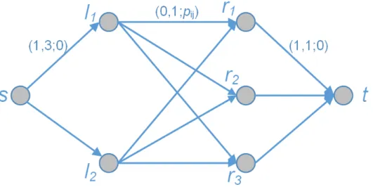
3.3 Cost flow algorithm. Three properties are on each link, denoted by (c0, c;p).
The leftmost node is the source (s), and the rightmost node is the sink (t). The NA nodes l1, l2,· · · , lNA and the NB nodes r1, r2,· · · , rNB represent NA
rows andNB columns in matrix W, respectively. . . 27
3.4 Non-weighted link and weighted link allocation example. Specifically, de-pendency links, in Fig. 3.4d and 3.4e, are allocated according to matrices Wnon−weighted and Wweighted, respectively. . . 28
3.5 Non-weighted networks comparisons. . . 33
3.7 Models simulations in real topologies. . . 37
3.8 Different degree distributions. . . 39
3.9 Three deployments within Barab´asi-Albert networks. . . 40
4.1 Middlebox-by-middlebox shortest paths. . . 44
4.2 Middlebox overloaded example. . . 45
4.3 SAN and BBA test network . . . 52
4.4 Test topology . . . 54
4.5 Evaluation of global LB routing . . . 55
4.6 End-to-end latency and loss rate . . . 57
4.7 Failures on different middleboxes. Firewall 2 is connected to Switch 4, and IDS 2 is connected to Switch 5. Firewall 2 provides critical resources while IDS 2 does not. . . 62
5.1 Test scenario 1: The attacker, switchS1, and the controller are involved in the DoS attack. The attacker conducts attacks through S1 toward the controller. Without loss of generality, we add an additional switch S2 and four hosts to represent the test scenario. Network topologies can consist of many switches and thousands of hosts. . . 69
5.2 The network becomes congested when attacks are launched. . . 71
5.3 There is only one attacker in the network. The green curve indicates the ideal amount of packets sent from the attacker. The red curve represents total packets received on the switch. The blue curve shows total packets received on the controller. . . 72
5.4 Test scenario 2: S2, and its two hosts H3 and H4, only work for testing controller availability. . . 73
5.5 Test scenario 3: N is the number of attackers. Each attacker has to be connected with a separated switch. We measure the controller availability using a test switch, and its two hosts H1 and H2. . . 73
5.6 Results of RTTs represent controller availability. We launch DoS attacks when there is a single attacker, 10 attackers, and 20 attackers, respectively. Each attacker must be connected with a separated switch. . . 74
5.7 Processing diagram of defense mechanisms. . . 77
5.8 Attacking rate is 130 PPS/attacker. X-axis indicates number of attackers. Blue histogram represents controller availability under attacks. Yellow his-togram represents controller availability after applying the blocking mechanism. 78
List of Tables
4.1 Routing path (S1 → Firewall→ IDS →S6) . . . 44
4.2 Test cases and results . . . 53
Acknowledgments
First of all, I am most grateful to my advisors, Dr. Caterina Scoglio and Dr. Don Gruenbacher for their guidance, encouragement, support, and patience. This work would not have reached completion without their help. They have provided numerous valuable suggestions, which are extremely helpful not only for my Ph.D. study but also for the rest of my life.
I sincerely thank my committee members, Dr. Dave Thompson and Dr. Todd Easton, for their precious time and helpful advice. I also appreciate Dr. Pavithra Prabhakar for donating her time to be the outside chairperson of my defense.
I would like to express my gratitude to my friends in the network science and engineering group: Heman Shakeri, Faryad Sahneh, Aram Vajdi, and all others. Thank you for the memorable time we spent together. I would also like to thank my friends at K-State: Futing Fan, Tianyu Lin, Qihui Yang, and Wenji Zhang for all the fun we had together.
Finally, I am thankful to my mother, Yanhua Zhang, and my father, Ning Li, for their continuous support over the years. Special thanks to my husband, Haotian Wu. You are my best friend and my best labmate. It is difficult to find the words to express my gratefulness for our being together.
Dedication
I dedicate my dissertation work to my dear husband, Haotian Wu, for his encouragement and patience, and to my daughter, Hannah Wu, for the happiness she brings to me. I also dedicate this work to my mother, Yanhua Zhang, and my father, Ning Li, for their constant support.
Preface
This dissertation, “Enhancing network robustness using software-defined networking,” is submitted for the degree of Doctor of Philosophy in the Department of Electrical and Computer Engineering at Kansas State University. The research was conducted under the supervision of Professors Caterina Scoglio and Don Gruenbacher.
To the best of my knowledge, this work is original, except where acknowledgements and references are indicated. Part of the work has been presented in the following published peer-reviewed journals or is submitted for publication:
1. Xin Li, Haotian Wu, Caterina Scoglio, and Don Gruenbacher. “Robust allocation of weighted dependency links in cyberphysical networks.” Physica A: Statistical Mechanics and its Applications 433 (2015): 316-3272.
2. Xin Li, Haotian Wu, Don Gruenbacher, Caterina Scoglio, and Tricha Anjali. “Efficient routing for middlebox policy enforcement in software-defined networking.” Computer Net-works 110 (2016): 243-2523.
3. Xin Li, Haotian Wu, Caterina Scoglio, and Don Gruenbacher. “A DDoS adversary model and defenses on the SDN control plane.” Submitted (2017).
This research is supported by the Kansas State Electrical Power Affiliates Program (EPAP) and the Department of Electrical and Computer Engineering at Kansas State Uni-versity.
Chapter 1
Introduction and background
Software-defined networking (SDN) is becoming increasingly important, bringing benefits that will potentially reform today’s computer network. We propose to enhance network robustness using SDN. In this chapter, we first present our motivations by introducing the role of SDN and the importance of network robustness in section 1.1. Second, we introduce the concepts of network robustness, SDN, OpenFlow, and middlebox in section 1.2. Third, we highlight our contributions in section1.3. Finally, the organization of this dissertation is introduced in section 1.4.
1.1
Introduction and motivation
Traditional computer networks rely on sophisticated protocols on legacy routers/switches to provide numerous services. This leads to Internet ossification, which means the current Internet has little space to scale. However, the population of network users is increasing dra-matically, and users’ requests are becoming more diverse. Data representing global internet traffic, in petabytes per month, is shown in Fig. 1.11.
Moreover, monthly active users of Facebook have been increasing dramatically over the last 13 years and reached 2 billion by the end of June 20174. Monthly global mobile data traffic is projected to be 49 exabytes by 2021, with annual traffic exceeding half a zettabyte5.
Figure 1.1: Global internet traffic (petabytes per month) over the past 11 years1.
The United States will need to invest up to $150 billion in fiber infrastructure over the next five to seven years to support networking demand6. Furthermore, recent data, as reported by Sandvine, indicate more than 70 percent of North American traffic is now streaming video and audio7. Streaming traffic is delay-sensitive and consumes large bandwidth.
Security issues are another concern on today’s network. Recently, credit-reporting firm Equifax revealed that hackers might have stolen financial and consumer data on at least 143 million customers8. Those data include birth dates, social security numbers, driver’s licenses and addresses, which could lead to severe identity theft issues, and immeasurably harm the U.S. finance credit system in the long run. In 2016, major Internet platforms and services couldn’t be accessed in Europe and North America, because Dyn servers were under DDoS attacks9. Such security threats have become even more severe in recent years.
Microsoft cloud user accounts saw a 300 percent increase in cyberattacks in 201610. Cisco’s
2017 mid-year cybersecurity report indicates that 34 percent of service providers lost revenue from attacks. Moreover, the new destruction of service (DeOS) attacks are not aiming at attacking, but at destroying networks by preventing defenders from restoring systems and
data11.
Traditional computer networks may face problems in adapting to the dynamics and re-quirements of numerous applications. Fortunately, the concept of SDN makes this possible by assigning networks more flexibility and programmability. SDN refers to a network ar-chitecture enabling programmability and separating the control plane from the data plane. It reforms sophisticated legacy routers/switches as simple forwarding elements, and further supports network scalabilities and innovations. It highlights the importance of software and allows us to manage network operations via open interfaces to further reduce expenditures. For example, AT&T CTO expects SDN to reduce operational expenses by 40 percent by 202012, and CenturyLink’s CEO, Glen Post, said his company remains on track to see at least $200 million in annual capital expenditures reduction13.
SDN is rapidly moving from vision to reality. Tech news indicated an incomplete list of 42 vendors offering SDN products14. Moreover, a number of SDN startups have already been bought by larger companies, validating their potential. In 2012, VMware bought Nicira for $1.25 billion. Then Juniper bought Contrail Systems for $176 million15.
Among its advantages, SDN brings opportunities to enhance a computer network’s ro-bustness. First, SDN provides centralized management with visibility of entire networks. One popular realization of SDN is OpenFlow16. The SDN controller supports acquiring flow statistics from OpenFlow switches in real time. This helps identify potential threats and speed up troubleshooting to guarantee network availability. Second, routing and rerouting flows are managed by the controller on the fly. For example, SDN incorporates middleboxes and dynamically routes flows along middlebox chains to accomplish network functionality. These middleboxes help improve network robustness, e.g., by use of a load balancer to cir-cumvent overloads and an IDS to detect anomalies. Moreover, SDN can flexibly reroute traffic bypassing malfunction devices or drop malicious flows. Third, flow tables on Open-Flow switches are updated by running programs on the controller. Network operators are no longer required to remotely log in and configure each switch, which makes network more ro-bust against any type of manual configuration errors. Moreover, SDN allows for eliminating policy conflicts and attacks by simply programming the OpenFlow controller.
When we enhance network robustness using SDN, we also need to study corresponding issues. Massive research has been exploiting opportunities and innovating promising appli-cations under SDN architecture; however, the design of SDN itself is conversely exposed to security challenges. The issue of SDN robustness becomes a concern, before it can become a substitute for traditional networks. On one side, we exploit the flexibility of SDN to enhance network robustness. On the other side, the decoupled architecture itself might be exposed to some security threats.
In general, today’s networks are independent networks. This leads to a situation where localized damage in one system will be extended to another system through their depen-dency links, triggering cascading failures and finally bringing large-scale damage2;17;18. For example, the 2003 Italy blackout affected a total of 56 million people. Consequently, network robustness is of great importance to ensure network availability, resilience, and adaption to changing scenarios.
1.2
Background
In this section, we introduce the concepts of network robustness and SDN, since SDN is the major technology to improve network robustness in this dissertation. Then, we present “OpenFlow,” an SDN standard, and “middlebox,” one type of network device.
1.2.1
Network robustness
Network robustness refers to a network’s ability to withstand failures and attacks — a critical attribute to evaluate networks. It ensures network availability, resilience, and adaption to changing scenarios.
Current networks (e.g. biological, biosocial, electric, electronic, etc.) are no longer in-dividual networks19–21, because one network often depends on another. For example, the
power network provides electricity to the computer network and, through the computer network, computers gather information reported from the power network, consequently
con-trolling the power network. Localized damage in one network will be propagated to the other one through dependency links, triggering cascading failures and finally bringing large-scale damage17;18. A robust framework with proper allocation of dependency links can protect networks from these large-scale damages. Moreover, SDN can be the enabling technology in the computer network, thus affecting the robustness of the network framework. With flexibilities of SDN to be discussed in subsection 1.2.2, and functionalities of middleboxes to be discussed in subsection 1.2.3, attacks and failures could be detected and eliminated within computer networks before being propagated, thus enhancing network robustness.
1.2.2
Software-defined networking
SDN is an emerging networking architecture with a design of decoupling the control plane and the data plane, which, consequently, simplifies network management, lowers the cost of network devices’ deployment, and potentially reforms today’s networks.
With increasing needs of numerous applications and enormous user demand, traditional computer networks are becoming more complex. In traditional computer networks, there are a large number of network devices, e.g., routers and middleboxes1.2.4, with complicated protocols running on them. Those devices are not only in charge of packet forwarding, but are also responsible for accomplishing network functions and conducting sophisticated management. Such integration of control logics and forwarding elements makes current IP networks very difficult to scale and evolve. We call it Internet ossification and its details are listed as follows:
1. Devices are vendor-specific. Network devices differ based on vendors and provide limited interfaces to be configured. This does not allow network operators to easily update network states. Network operators have to configure each network device separately. They also need to reconfigure them when there are network failures and policy changes. Moreover, such configurations are error-prone and very difficult to scale.
2. Protocols are sophisticated. To accomplish various policies, a set of protocols need to be implemented. As needs of numerous applications increase, these protocols become
more sophisticated and may conflict with each other. Network evolvement is caught in a dilemma as to whether to gain more intelligence and sophistication, or not.
3. Testing platforms are insufficient. New ideas should be tested in realistic settings to validate their practicality. However, research traffic cannot be isolated from production traffic and this might lead to severe consequences in current IP networks16. A new routing protocol can take five to 10 years to be fully designed, evaluated, and deployed in current IP networks22.
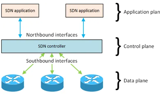
SDN architecture consists of three planes and two interfaces, that is, application plane, control plane and data plane; and northbound interface and southbound interface, shown in Fig. 1.2. The biggest innovation is the separation of the control plane and the data plane. All control logics are defined in the control plane, and the data plane is only responsible for forwarding. That simplifies network management and further allows network to scale to adapt to increasing demands. The three planes are logically separated, but they might coexist with each other physically.
Figure 1.2: SDN architecture consists of three planes and two types of interfaces.
1. Centralized management — an SDN controller has an overview of entire networks, sim-plifies traffic management to adapt to different application requirements, and provides better network supervision23;24. All control logics are managed by authenticated appli-cations and dispatched through the control-to-data plane channel using an OpenFlow protocol.
2. Flexibility — SDN’s data plane is only responsible for forwarding packets. It assigns more flexibilities on the networks without manually configuring legacy routers/switches. Once network policies or conditions change, switches receive updated commands from the controller and simply follow those instructions.
3. Programmability — SDN architecture introduces the ability of programmability. Network operators can control and update network behaviors by programming each network device dynamically via open interfaces. Such software programs are easier operated and less error-prone25.
4. Innovation — SDN allows network innovations by isolating research traffic from pro-duction traffic, and helps with new protocol tests in realistic settings. It also provides functionalities of access control, load balancing, network monitoring, etc. to gradually substitute traditional computer networks, and further stimulates innovations.
1.2.3
OpenFlow
OpenFlow is the current SDN de-facto standard26. It is a communication protocol between the control plane and the data plane. Unless specified, switches in the data plane discussed in this dissertation are OpenFlow-enabled switches.
OpenFlow switch
An OpenFlow switch consists of one or more flow tables, a group table, and one or more OpenFlow channels connected to a remote controller27.
Figure 1.3: A flow entry consists of header fields, actions, and counters.
The flow table contains a list of flow entries 1.3, which perform packet matching and define forwarding actions. Each flow entry in the flow table consists of three fields: header fields, actions, and counters. In the header fields, 12 fields, defined in OpenFlow 1.0, classify a flow and provide various matching possibilities to meet different applications’ requirements. Actions can be various and flexible — dropping the flow, forwarding the flow, or even chang-ing flow content, etc. We can also customize actions. Counters are collected at the line rate, and further used for network monitoring and management.
The OpenFlow channel refers to the interface connecting the OpenFlow switch to the controller. OpenFlow defines a set of messages, e.g., symmetric messages “hello” and asyn-chronous messages “packet-in,” to communicate or update status with the controller via this channel. The controller can also configure and manage OpenFlow switches via the channel. In addition, such communication is optionally secured by a transport layer security (TLS) protocol.
Flow forwarding
When a packet arrives at an OpenFlow switch, packet header fields are extracted to try to match the header fields of flow entries. When it matches the header field in a flow entry, it will conduct the corresponding actions. If a flow cannot find a matching flow entry, it will be encapsulated with an OpenFlow protocol header and forwarded to the controller to request
a new flow-entry installation. After the new flow entry is installed, matched packets will be forwarded according to its actions.
The new flow entry can be installed either proactively by the controller or as requested, indicated above. The controller can also update and delete flow entries in flow tables.
1.2.4
Middlebox
Middlebox is a graphic description of an existing internet phenomenon providing network functions other than IP routing. Since it is implemented as an intermediary box between a source host and a destination host, it is called “middlebox”28. In traditional computer networks, all functions above the IP layer, except IP routing functions, can be considered as middlebox functions. For example, firewalls, proxies, DNS servers, and load balancers are middleboxes, while IP routers are not. In SDN networks, switches are not considered as middleboxes, while other functions are, as indicated above29. Today’s network relies on these middleboxes to guarantee critical network functions, e.g., security inspection and performance improvement. For example, load balancers are used to circumvent overloads, and further improve network performance and robustness. RFC 3234 details taxonomy and issues about middleboxes28.
Middlebox deployment
Middleboxes can be deployed in path 1.4 or off path 1.5. Off-path deployment is more robust and can ensure end-to-end connectivity when failures occur. It is also more efficient and flexible, since we only route flows to go through middleboxes as needed.
Middlebox policy chain
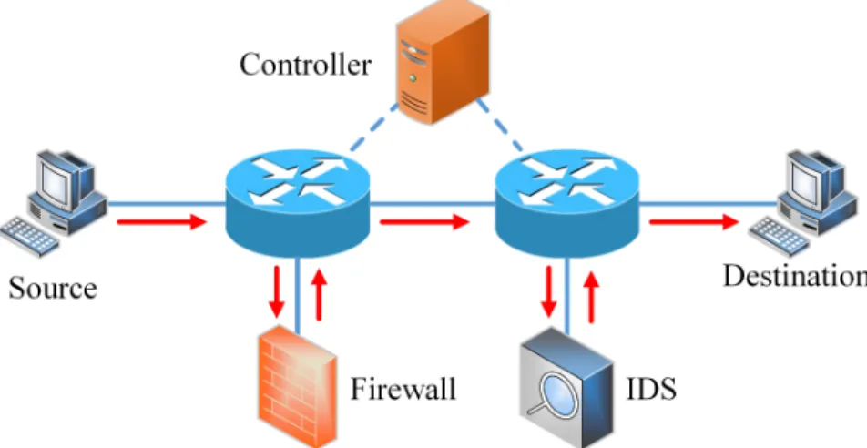
Network applications require traffic to sequence through multiple types of middleboxes to accomplish desired network functions. We call this “middlebox policy chain.” For example, flows have to first go through a firewall and then an IDS for security purposes29, shown in
Figure 1.4: Middlebox in-path deployment — all flows on the red path are forced to be sent through the middlebox, such as a firewall (FW).
Figure 1.5: Middlebox off-path deployment — secure flows are sent along the green path, while others are sent through the firewall for inspection.
Figure 1.6: Example of a middlebox chain — flows sequenced through a firewall and then an IDS.
In a larger network with numerous middleboxes, flow routings along middlebox chains become complex23, which might create false configurations. It is also difficult to dynamically update routing paths. It is even more challenging to enable middlebox chains within limited network resources.
1.3
Contributions
We vertically dive into enhancing network robustness by constructing a topological frame-work, making routing decisions, and protecting the SDN controller. Our major contributions can be summarized as follows:
1. We have designed and thoroughly tested an optimization-based scheme to allocate depen-dency links within a budget constraint, where the numbers of nodes in the two networks are not identical. To this end, we have built a realistic cyber-physical network framework with one-to-multiple dependencies, two unequal-size individual networks, and weighted dependency links. Cyber-physical networks are in essence interdependent networks, where one network supports and affects the other through dependency links. Localized net-work failures and attacks are amplified and exacerbated back and forth between the two networks due to their interdependencies. We allocate dependency links to obtain more network robustness under this realistic framework.
2. We have developed two routing schemes for middlebox policy enforcement to improve network robustness. This is the first work to handle failures in middlebox chain scenarios using OpenFlow. With our designs, network resources are managed efficiently to circum-vent overloads, and the network can rapidly respond to middlebox failures. Consequently, network robustness is improved. Moreover, results of the optimization on a test topol-ogy include an increase up to 26.4 percent of the throughput, with respect to sequenced shortest-path routing.
3. We have explored vulnerabilities of the SDN controller from the attacker’s point of view and have detailed the adversary model. We have presented preliminary results for several
strategies to protect the controller from saturation attacks. This work contributes funda-mentally to detect and mitigate the SDN control plane’s vulnerabilities, and to further enhance network robustness.
1.4
Organization
This dissertation is organized into chapters. In chapter 2, we present a thorough literature review on the issues of network robustness. In chapter3, we propose a novel robust network framework and allocate dependency links to obtain more network robustness. In chapter 4, we further enhance network robustness by managing middlebox policies and handling mid-dlebox failures using SDN. In chapter 5, we build a detailed adversary model to identify vulnerabilities of the SDN control plane, and present preliminary results on possible defense mechanisms. Finally, we conclude this dissertation and discuss future work in chapter 6.
Chapter 2
Literature review
Software-defined networking (SDN) is an emerging networking architecture that reduces com-plexities of network traffic management and presents a design of programmable networks that can adapt to changing application requirements25. SDN provides functionalities of access
control, load balancing, network monitoring, etc. to supplement traditional computer net-works, and further stimulates more innovations. In particular, SDN brings opportunities to network robustness, for example, fine-grained control over network-based security func-tions; flexibly rerouting traffic bypassing malfunction devices or dropping malicious flows; and other innovative applications such as protecting web servers from TCP SYN flooding, etc.3;30;31 Massive research has been exploiting opportunities and innovating promising
ap-plications under SDN architecture; however, the design of SDN itself is conversely exposed to security challenges. Moreover, a computer network is always coupled with other networks, and a localized failure might destroy the entire network. It is of great importance to study network robustness. We define network robustness as the network ability to withstand pos-sible network failures or attacks; and it ensures network availability, resilience, and adaption to changing scenarios.
SDN brings opportunities to enhance the computer network’s robustness. First, it pro-vides better network supervision. The controller has an overview of the entire computer network and can acquire flow statistics from OpenFlow switches on the fly. Thus, we can
rapidly identify network failures or attacks. One common application is to identify attack-ing flow patterns from collected data32;33. Second, SDN allows dynamicality of complex, network-policy management. Data plane is only responsible for packet forwarding, to avoid complicated configurations. For example, SDN dynamically routes flows along a middlebox chain to accomplish network functionalities3;34. These middleboxes help improve network robustness, e.g., a load balancer is used to circumvent overloads and an IDS is used to de-tect anomalies. Third, SDN allows elimination of policy conflicts35and mitigates attacks by simply programming the OpenFlow controller.
We particularly outline how SDN helps solve the middlebox chain problem. Network applications require traffic to sequence through multiple types of middleboxes to accomplish desired network functions. For example, web traffic needs to go through a proxy and then a firewall36. To fulfill network functions, various types of middleboxes are utilized, and each type might have a hundred devices in a large network29;37. In traditional computer networks, traffic steering to meet the above goals is a critical problem23, which might create false configurations. It is also difficult to dynamically update the routing policy. It is even more challenging to enable the stateful policy routing (middlebox policy chain) within limited network resources (network link bandwidth, middlebox-processing capability, and switch high-speed searching memory).
The problem of routing under middlebox sequence constraints has recently gained re-markable attention due to the role played by many network devices called middleboxes (e.g., firewalls, VPN gateways, proxies, intrusion detection systems (IDS), WAN optimizers) on network performance38–42. To enforce middlebox policies, a novel middlebox architecture was presented by Sekar et al. in38. In this paper, the authors designed a network-wide con-troller and a local coordinator to manage middlebox resources, resembling the architecture of SDN networks. As a matter of fact, a centralized SDN controller makes a network trans-parent and synchronous39, as well as more efficient for network administrators to manage.
Furthermore, Joseph et al. proposed a policy-aware switching layer to enforce middlebox policy and increase middlebox utilization40. They also presented an off-path middlebox
link multiple times, increasing the probability of link overload. Fayazbakhsh et al. further modified legacy middleboxes to support FlowTags used to differentiate flows with different policy requirements41. Alternatively, OpenFlow allows the identification of stateful policy flows using available fields in the packet header. Using OpenFlow, Qazi et al. elaborated on the complexity of selecting middleboxes and scheduling flows, and simplified the middlebox traffic steering problem by offline pruning some of the less-promising routing paths29. The proposed offline calculation is time consuming, and it was performed each time failures oc-curred or policy changed. This aspect is problematic, since networks should quickly respond toward middlebox/link overloads and failures. In summary, open issues are as follows: how to select possible routing paths with middlebox policy enforcement, and how to quickly assign flow routing paths to maintain network performance. In solving middlebox chain problems, resources on the middleboxes are another constraint. We take on solving these open issues in chapter4.
Another topic of research in the field of middlebox management concerns how to deal with link failures and middlebox failures43–46. Research indicated that middleboxes con-tribute to 43 percent of high-severity incidents28;46. Thus, it is critical to study middlebox failures. Existing solutions are either to prevent the effect of middlebox failures before-hand47, or react after middlebox failures; for example, reconstruct middlebox states after failures48. However, today’s network relies on sequenced types of middleboxes to provide network functions, and different types of traffic go through different sequences — both of these being beyond the scope of existing approaches. Restarting middleboxes is a common approach to dealing with middlebox failures, but few articles considered the impact during the restarting period. In addition, when application requirements change, middlebox policy will be updated. To avoid misconfiguration during policy updates, SDN’s centralized and programmable management helps solve this middlebox policy routing problem. Therefore, we are the first to consider middlebox failures in the middlebox chain problem, and then mitigate these failures’ consequences using SDN. This will be introduced in chapter 4.
As SDN invokes huge interest from both academia and industry, it is rapidly proceeding from vision to reality. However, some researchers are arguing that SDN conversely brings
several security threats due to nature of separation between the control plane and the data plane49–53. It is not clear whether SDN brings more benefits, or conversely, more threats, to today’s networks.
Several components in SDN architecture are exposed to robustness issues. Attacks might occur on the application plane, the control plane, the data plane, the northbound interface, or the southbound interface as shown in Fig. 1.254–61. First, attacks toward the controller can lead to a disaster for the entire network. Thus, the controller is a particularly attractive attack target. The controller might be exposed to unauthorized access and exploitation through open interfaces (northbound and southbound interfaces). Second, when multiple applications are deployed on the application plane, conflicting flow-rule problems may arise35. Third, the control plane and the data plane are both exposed to scalability issues. For example, the controller might be overwhelmed by an excess of flow-entry installation requests and switches might fail to buffer all new flow packets. This can be exploited by attackers to launch denial of service attacks.
OpenFlow is an enabler of SDN. In an OpenFlow network, when a packet arrives, a switch forwards the packet based on the matching flow entry. When no flow entry matches, the switch will generate a packet-in message to the controller for a flow-entry setup. Assume a large volume of table-miss packets are coming. The same number of requests will be sent from the switch to the controller62. Such requests will overwhelm the switch-to-control channel, exhaust the controller computation resources, and further lead to controller dysfunctionality. As network size scales or user requirements vary, the controller’s scalability issue will become more severe. Many efforts have been made to solve this scalability issue. Researchers proposed use of distributed controllers to decentralize the calculation burden of the single controller63 and further protect the entire network from the single-point controller failure. Moreover, some research on wildcard rules is aiming at reducing the number of requests from the data plane64;65. All those solutions help improve the control plane scalability. They are
also valuable for denial of service (DoS) attack elimination strategies, due to the fact that control plane scalability issues and control plane DoS attacks are both resource consumption issues. However, when DoS attacks are launched, those strategies are no longer sufficient.
To mitigate DoS attacks, we can detect a user with abnormal behaviors by simply setting a rate-limiting threshold. When a user sends more flows than the threshold, we can block all flows from that user66. However, those requests could come from legitimate users and simply blocking all suspicious flows unavoidably affects flows from legitimate users. Moreover, in the SDN architecture, attackers can generate excessive short new flows to overwhelm the controller, but absolutely skip rate limiting. In this case, total rate of those attacking flows is very small, and it’s hard to block the attacks by setting a rate-limiting threshold.
Crafting a huge amount of short table-miss packets forces the switch to inquire the controller, leading to network dysfunctionalities. Such new table-miss packets’ flooding is called “request flooding” for short in this dissertation. Many research groups are working on this topic52;53;62;67–74. Request flooding will lead to switch software components overload, switch-to-controller channel congestion, switch flow-table overflow, and controller’s resource saturation71. Among them, controller-resource saturation is destructive to the entire net-work. Avant-Guard72 and Lineswitch73;74 proposed a proxy-like switch extension to shield the controller from attacks. Such a method is effective when it comes to TCP-SYN flooding. We are targeting a more general request flooding, also indicated in53;62;67–71. OF-GUARD53 and Floodguard62 built an additional data plane cache to temporarily hold excessive new packets to protect the controller. Zhang et al.71 and Wei et al.67 proposed to mitigate this request-flooding attack from the controller side, instead of adding any extra complexity on the data plane. Zhang et al. introduced weighted, fair-sharing queues to reduce the packets from attackers being served71. Wei et al. dynamically maintained a trust list and updated each user’s trust value to block the attackers67.
Thus, several challenges have arisen, as follows: Will the controller have enough CPUs and memory to hold queueing lists? Does the controller work to completely block attackers? How do we differentiate legitimate users from attackers? In this dissertation, we explore controller vulnerabilities from the attacker’s point of view, and detail an adversary model and defenses. This will be introduced in chapter 5.
Regarding the robustness of cyber-physical systems, Buldyrev et al. provided a one-to-one node dependency interdependent network model to describe the cascading failures
caused by the dependencies between two individual networks18. Cascading failures under
random attack18;75 and targeted attack76;77were further studied in order to develop suitable protection strategies. Not only node correlations78 and clustering coefficients within one in-dividual network79, but also node coupling approaches of the nodes from two networks20;77;80 influence network robustness. Schneider et al. indicated that choosing a fraction of nodes as autonomous beneficially increased robustness81. Mirzasoleiman et al. introduced weighted individual networks and studied link-load effects on robustness in82. Results in83–85 com-prehensively indicated and proved a coupling threshold existed for interconnected network structural transitions from two independent functioning networks to a whole system. Fur-ther research in edge attack raFur-ther than node attack was produced86. Gao et al. generalized interdependent networks with two individual networks tonindividual networks87. However, all research is based on the one-to-one node dependency interdependent network model in18. The one-to-multiple dependency model brought up in88 is more realistic than the one-to-one node dependency model in previous papers. Reis et al. extended this to study indegree-indegree and indegree-indegree-outdegree relationships, that is, one node can have multiple supports from another network89. Ya˘gan et al. proved that a proper allocation of dependency links in their one-to-multiple dependency model would contribute to a more robust system90. Their dependency model is valuable, but in reality, it is always the case that one network has mul-tiple dependencies from the other network. The numbers of nodes in two individual networks are not equal as well. Weights of dependency links are no longer identical. In chapter 3, we build a realistic robust interdependent network model and allocate dependency links to make the network more robust from cascading failures. With this allocation, we do not expect localized damage in the computer network to propagate to an uncontrollable disaster for the entire cyber-physical networks.
In summary, in this dissertation, we are analyzing and solving some challenging issues to make networks more robust toward failures and attacks.
Chapter 3
Robust network framework
In this chapter, we explore a robust cyber-physical network framework. Interdependent network models are often used to show how one network has an effect on another network through their dependencies. We propose a novel interdependent network model, which con-sists of two individual networks with unequal numbers of nodes and one-to-multiple weighted dependency links between the two networks. Based on realistic assumptions, this model dif-fers from previous works that considered equal numbers of nodes in the two networks and identical under limited budgets. We formulate an optimization problem to allocate depen-dency links using least resources. This novel model enhances the practicability of traditional cyber-physical system structures, but it makes the dependency-link deployment problem more complex and the optimization problem cannot be solved in large networks. To overcome this problem, we propose a new algorithm based on a revised network flow method. Exten-sive simulations on random networks and real networks show that our deployment method produces topologies that are more robust than the ones obtained by other deployment tech-niques. Results indicate that our algorithm is efficient and cost-effective in designing robust interdependent networks, and our deployment method is suitable for networks of any size.
3.1
Interdependent network model
We build a novel network model for cyber-physical systems considering dependencies between individual networks. First, we introduce interdependent network models. Second, we present how one network affects the other in the cyber-physical systems. Third, we further discuss individual network models and their dependencies.
3.1.1
Classic interdependent network model
Buldyrev et al. presented an interdependent model for a blackout in Italy in 200318. They considered two networks, A and B, with the same number of nodes. Network A is a power network, and the nodes of network A can be considered as power stations; network B is an Internet network, and the nodes of network B are internet servers. Functioning of a power station relies on control information provided by an internet server, and an internet server needs power supply from a power station. The two networks are one-to-one coupled with each other and rely on the other to provide critical resources. Connections between two individual networks are presented by their dependency links.
3.1.2
Realistic interdependent network model
In real-world interdependent networks, a node in a network is often supported by multiple nodes in another network. A one-to-one node dependency model is no longer suitable for further interdependent network studies. And, it is always the case that numbers of nodes in two individual networks are not equal in reality. Our novel interdependent network model can be considered as one of our contributions. Moreover, costs of allocating dependency links rely on geographical features, corresponding node loads, etc. Thus, dependency links should be weighted rather than being assumed equal. Consequently, a one-to-one node-dependency-link model is not realistic, but one-to-multiple dependency links with various weights must be studied. Furthermore, dependency-link allocation designs can greatly affect the robustness (R) of interdependent networks.
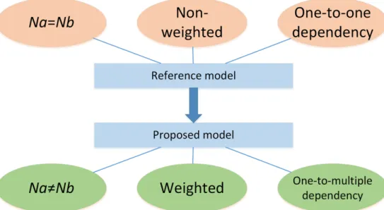
Figure 3.1: Compared with previous models, we build a realistic cyber-physical network framework with one-to-multiple dependencies, two unequal-size individual networks, and weighted dependency links.
Our model consists of three parts: two individual networks (A and B) and their de-pendencies91. Individual network models will be introduced in subsection 3.1.4, and their dependencies are discussed in subsection 3.1.5. Two nodes in the same individual network are connected by connected links, while two nodes from different individual networks are in-terdependent by dependency links. Numbers of nodes in networkAandBare denoted byNA
and NB, respectively, and dependency links are weighted. If all dependency links are
iden-tical, we call them non-weighted links or weighted links with weight equal to 1. The largest component18;88;92, i.e., largest connected subgraph, represents a functioning component in each individual network. We allow for one-to-multiple dependencies in the interdependent network, rather than one-to-one dependency. Moreover,NAandNBare not necessarily equal
in our model. The improvement of our model from previous models is shown in Fig. 3.1.
3.1.3
Cascading failures
Cyber-physical systems are more likely to fail because of interdependence between cyber networks (e.g., computer networks) and physical systems (e.g., power networks). If a power station fails, the assumption is made that it will no longer supply power to the linked
computers in computer networks. In addition, other power stations lose connections with that station and must redistribute their loads. Therefore, we have an assumption that if some nodes fail, the links (connected links and dependency links) connected to these nodes fail. Then we obtain several disconnected groups of power stations after failures appearing in the power network, and assume the largest component in the power network works as the functioning component, rather than other small connected components88. The same thing happens in the computer network, that is, we only consider the largest component. The second assumption is that nodes not in the largest component (of its own network) fail. Moreover, if no power station supplies power to a computer, the computer will not operate, and vice versa, leading to the third assumption: nodes with no dependency links fail. NA∗ andNB∗ represent the numbers of nodes in two stable networks when cascading failures come to an end. Based on initial and stable network states, robustness is defined as:
R=0.5×(N ∗ A NA + N ∗ B NB ) (3.1)
Cascading failure example
In Fig. 3.2, Ai indicates the ith node in one network A, while Bj represents the jth node in
another networkB. The connection betweenAiandBj is represented bymij. The connection
betweenAi andAj is represented byaij, and the connection betweenBi andBj is represented
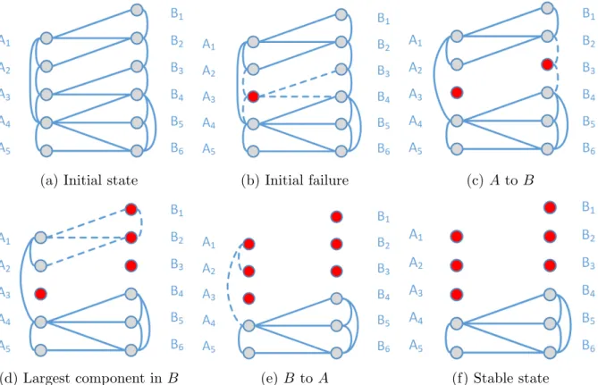
by bij, respectively. In Fig. 3.2a, we see an initial state of the interdependent networks
with one-to-multiple dependencies and unequal numbers of nodes in the two networks. We consider the initial state in (a) as NA= 5 and NB = 6. In Fig. 3.2b, the initial failure rate
happening to networkAis 0.2. It illustrates whenA3 is attacked, the connected linksa32,a34
and dependency linksm33,m34 fail. NodesA1,A2,A4, andA5 are in the largest component.
Network A influences NetworkB through m33 and m34. In Fig. 3.2c,B3 has no dependency
links, so B3 fails and the links connected to B3 fail. Node B1 and B2 fail as they become
disconnected from the functioning component of networkB. NetworkB influences Network Athroughm11,m12, andm22, as shown in Fig.3.2d. Fig.3.2e indicates thatA1 andA2 have
(a) Initial state (b) Initial failure (c) AtoB
(d) Largest component inB (e)B toA (f) Stable state
Figure 3.2: A cascading failure process is illustrated.
no dependency links. In Fig. 3.2f, we have a stable state after cascading failures. A4A5 and
B4B5B6 are existing nodes, i.e., NA∗ = 2 and NB∗ = 3 at this time. According to Eq. (3.1),
R= 0.5×(2/5 + 3/6) = 0.45. It is noted that robustness (R) in the following simulations is calculated by Eq. (3.1).
3.1.4
Individual network model
Erd˝os-R´enyi (ER)93 and Barab´si-Albert (BA)94 are both random graph models. In the ER model, each vertex has the same probability with a fixed number of edges. The BA model is used to generate random scale-free networks using a preferential attachment mechanism. It represents some real networks with the feature of containing few nodes (a.k.a., hubs) with unusually high degree. We use these two typical random network models as the individual network models to generalize our results. We also apply our strategies with real network topologies in section 3.7.
3.1.5
Discussion of dependency links
This work designs how to allocate dependency links with prior information of link weights. The weights show the differences among dependency links. A larger weight represents a higher cost to allocate this dependency link. We use a limited budget (total weights: tw) to build all dependency links. To the author’s best knowledge, this is the first work to apply the concept of limited budget to arrange dependency links from an engineering perspective. Link allocation in this work shows how nodes in two individual networks are dependent and is performed as an extensive study of node coupling75–77. In the following sections, we focus
on designing allocation strategies of dependency links.
3.2
Dependency-link allocation
Our design of dependency-link allocations is divided into the following two steps:
Step 1: Basic connectivity — each node has at least one dependency link with least total weights.
Step 2: Augmented connectivity — we use the remaining budget to set up additional de-pendency links.
3.2.1
Problem formulation
In Step 1, each node in one network requires power or information from the node in another network through dependency links. Therefore, each node in the interdependent networks should have at least one dependency link in our design. Using least total weights to achieve basic connectivity becomes an optimization problem. Different weights of dependency links complicate this problem. We adapt a revised network flow algorithm95 to solve it.
In our model, the numbers of nodes in two networks are unequal. The number of links should be no less than the larger number of nodes in two networks, so that each node in that network has one dependency link, while each node in the opposite network has at least one dependency link. In this chapter, we assume the number of nodes in the right side network
(NB) is larger than the number of nodes in the left side (NA). Therefore, a total ofNB links
is needed to achieve basic connectivity using the least weights. We generally describe the Step 1 as follows: minX i,j mij ×Wij (3.2) X i mij = 1 (3.3) X j mij ≥1 (3.4)
Matrix m is a 0-1 matrix, which means that mij could only equal 0 or 1. If the link
between Ai and Bj is selected, mij is equal to 1. Matrix W is the matrix containing all
dependency-link weights in the network, and Wij represents the weight of edgemij.
3.2.2
Existing tools limitation
Solving the basic connectivity is an optimization problem. However, due to the large numbers of variables in large networks (e.g., if 1,000 nodes are in each network, 1,000,000 variables will be in our problem 3.2.1), this problem cannot be solved by traditional tools such as LINGO or MATLAB.
3.3
Revised network flow algorithm
We revise the network flow algorithm96;97 to solve Step 1. This is another highlight of this
chapter. The new algorithm is the minimum cost maximum flow with lower and upper bounds (cost flow for abbreviation in the following).
3.3.1
Notations of cost flow
G(V, E) is a finite directed graph in which every edge (u, v) ∈ E has a non-negative, real-valued capacityc(u, v), lower flow boundc0(u, v), and a real-valued costp(u, v). If (u, v)6∈E,
we assume thatc(u, v) = 0,c0(u, v) = 0, andp(u, v) = 0. The three properties of edge (u, v)
can be written as (c0(u, v), c(u, v);p(u, v)) for simplicity.
3.3.2
Basic constraints in cost flow
LetN =G(V, E) be a network with s, t∈V being the source and sink, respectively.
A flow in a flow network is a real function f : V ×V →R with the following properties for all nodes uand v. Notation f(u, v) is the network flow from u tov.
Capacity and lower flow bound constraints: c0(u, v)≤ f(u, v) ≤c(u, v). The flow along
an edge is larger than c0 but cannot exceed its capacity c.
Skew symmetry: f(u, v) =−f(v, u). The net flow of link (u, v) must be opposite of the net flow of (v, u).
Flow conservation: P
v∈V f(u, v) = 0, unless u = s or u =t. The net flow of a node is
zero, except for the source, which “produces” flow and the sink which “consumes” flow. Cost notation: p(u, v) denotes the unit cost of flow from node u to node v, and P(G) denotes total cost of flow from s tot. Therefore, P(G) = P
(u,v)∈Ep(u, v)×f(u, v).
3.3.3
Algorithm process
In a basic connectivity problem, we construct the network as follows: for a weight matrixW with size NA×NB, we build NA nodes denoted by l1 through lNA, and NB nodes denoted
by r1 through rNB. An edge (li, rj) has properties denoted by (0,1;Wij), which means for
any integer 1 ≤i ≤NA and 1 ≤ j ≤NB, there is an edge between node li and rj, and the
lower flow bound is 0, capacity is 1, and cost is the corresponding value in the weight matrix, Wij. In addition, we add an edge (s, li) with (1, NB; 0) for everyli, and an edge (rj, t) with
(1,1; 0) for every rj, as shown in Fig. 3.3, and then run the minimum cost maximum flow
algorithm on this network. All these edges are directed edges.
Residual capacity of an edge is denoted by cf(u, v) and cost of this edge is denoted
pf(u, v). If (u, v) ∈ E, then cf(u, v) = c(u, v)− f(u, v), pf(u, v) = p(u, v); cf(v, u) =
Figure 3.3: Cost flow algorithm. Three properties are on each link, denoted by (c0, c;p).
The leftmost node is the source (s), and the rightmost node is the sink (t). The NA nodes
l1, l2,· · · , lNA and theNB nodesr1, r2,· · · , rNB representNArows andNBcolumns in matrix
W, respectively.
Gf(V, Ef), representing the amount of available capacity. This residual network is a new
directed network compared to the original network with two properties on each edge: residual capacity and cost. Augmenting is expected to happen in this residual network. A path can be observed from u to v in the residual network, even though no path is evident from u to v in the original network. If (u, v) ∈ E, we point out p(v, u) = 0 in the original network; however, we have pf(v, u) =−p(u, v) in the new network. Since flows in opposite directions
cancel out, decreasing the flow fromv touand increasing the flow from utov are identical. An augmenting cycle is a negative-weight cycle in the residual network. Weight in the network is the cost; sending flow around the cycle strictly decreases total cost and preserves feasibility. A feasible flow f is optimal if and only if there are no augmenting cycles.
In a regular minimum cost maximum flow problem, first we should find maximum flow with a feasible solution, and then find an augmenting cycle in order to identify minimum cost. However, in this problem, all edges from rj to t are identical; every edge has both
lower bound and capacity equal to 1. Consequently, f(rj, t) is equal to 1 for any j, and
thus maximum flow of this network is NB. Therefore, the procedure of finding maximum
repeatedly, minimum cost can finally be found. A negative-weight cycle can be found by utilizing a shortest-path algorithm, for example, shortest path faster algorithm (SPFA).
3.3.4
Relationship between flow graph and link selection
We propose this cost flow algorithm to solve the following problem: in a bipartite graph, we select the minimum number of links (equal toNB), such that all nodes are covered and have
the minimum total weights. Every feasible flow in the graph corresponds one-to-one to a set of links, which satisfy the constraints in Eq. (3.2), (3.3), and (3.4).
(a) The basic connectivity (b) Uniform distribution (c) Random distribution
(d) An example of weighted net-works
(e) Another weighted networks
Figure 3.4: Non-weighted link and weighted link allocation example. Specifically, dependency links, in Fig. 3.4d and 3.4e, are allocated according to matrices Wnon−weighted and Wweighted,
respectively.
The capacity of link (rj, t) is 1, which means that at most one node can provide node rj
of flow. These two constraints guarantee that node rj will acquire exactly 1 unit of flow;
therefore, the constraint in Eq. (3.3) is guaranteed.
Similarly, the capacity and lower bound of link (s, li) guarantee the constraint in Eq.
(3.4).
Matrix f can be any feasible flow matrix, and the selection of f does not influence the final result; it is only an initial guess. The initial guess off in our simulation is:
Algorithm 1 Cost Flow
Input: W (NA×NB matrix) Output: f (0-1 Matrix) 1: function MinCostMaxFlow(W) 2: p← 01×1 01×NA 01×NB 01×1 0NA×1 0 W 0 0NB×1 0 0 0 01×1 0 0 0 3: c← 01×1 ∞1×NA 01×NB 01×1 0NA×1 0 1 0 0NB×1 0 0 1 01×1 0 0 0 4: c0 ← 01×1 11×NA 01×NB 01×1 0NA×1 0 0 0 0NB×1 0 0 1 01×1 0 0 0
5: f ← any matrix that is a feasible initial flow
6: while true do
7: Dis←0 with the same size asp
8: for alli, j do
9: if fij < cij then Disij ←pij
10: if fij > c0ij then Disji← −pij
11: end for
12: Cycle←SPFA(Dis) . Use SPFA algorithm to find negative cycle.
13: if Cycle not found then return f
14: for each edge (u, v) on the cycle do
15: fuv←fuv+ 1
16: fvu←fvu−1
17: end for
18: end while
f ← 01×1 K 01×NB 01×1 0NA×1 0 D 0 0NB×1 0 0 1 01×1 0 0 0 K ← 11×(NA−1) NB−NA+ 1 D← 1 0 · · · 0 0 · · · 0 0 1 · · · 0 0 · · · 0 .. . ... . .. ... ... ... 0 0 · · · 1 1 · · · 1
3.4
Dependency-link allocation example under limited
budget
We use an example to describe various strategies of non-weighted link and weighted link allocations as shown in Fig. 3.4. In Fig. 3.4, blue links are allocated in basic connectivity and yellow links show augmented connectivity by utilizing the remaining budget. Fig. 3.4a
shows the basic connectivity.
3.4.1
Parameters of the example
Here, we have parameterstw = 8, NA= 4, NB= 5.
Wnon−weighted = 1 1 1 1 1 1 1 1 1 1 1 1 1 1 1 1 1 1 1 1
Wweighted = 1 2 2 2 2 2 1 1 2 2 2 2 1 1 2 2 1 2 1 1
3.4.2
Adding non-weighted links
Comparing Fig. 3.4b and Fig. 3.4c, the numbers of dependency links are identical using the limited budget, while distributions of these links differ. We offer simulation results and analysis on different distributions of links in section 3.5.
3.4.3
Adding weighted links
With matrix Wweighted, we compare various sequences of dependency-links allocation in
Fig.3.4dand Fig. 3.4e, resulting in different numbers of links using an equal limited budget. We discuss the sequence of allocating dependency links and analyze simulation results in section 3.6.
3.5
Non-weighted dependency-link model simulation
and comparison
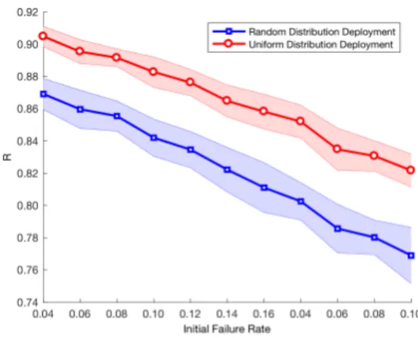
Non-weighted dependency links, which can be assumed as links with the same weight 1, can largely simplify the Step 1 talked about in section3.2. In Step 2, considering the remaining budget, no matter which links are selected, the number of links is equal because of the identical weight of all links. However, the network robustness differs based on its deployment. Many studies have indicated that node degree distribution is critical for robustness in the interdependent networks. The aim of augmented connectivity is to achieve minimum variance of node degrees, referred to as uniform distribution deployment in Fig.3.4b. Also, instead of adding links in this pattern, randomly adding additional links, known as random distribution deployment, is shown in Fig. 3.4c.
We apply ER networks to generate the topologies of two individual networks; however, ER networks generated in each run in the simulation are not identical. Due to the stochastic nature of ER networks, we simulate multiple times in order to obtain the average performance of both deployment methods. The relationship between numbers of nodes in two individual networks is formulated as NB = (1 +α)×NA. Therefore, node numbers NA and NB have
identical magnitude and ratio, making simulation results comparable. These descriptions are also suitable for the weighted model in section3.6.
Two non-weighted dependency-link deployments are simulated in Fig.3.5aand Fig.3.5b. In these two distributions, we have the same average node degree. Also, in the basic con-nectivity, we guarantee every node is connected to at least one node on the other side (left side or right side). However, performances of these two distributions are not identical. The simulations indicate uniform distribution is more robust than random distribution, as shown in Fig. 3.5a and Fig.3.5b. In81, the authors indicated similar conclusions under equal num-bers of nodes in two networks. Our simulation results can be considered as the