Practicalities of Implementing Component-Based
Development and Model-Driven Architecture
Jorn Bettin SoftMetaWare, PO Box 617, Waiheke Island, New Zealand
[email protected] http://www.softmetaware.com
Abstract. Although component-based development provides the concepts and mechanisms to manage complexity in large software development efforts, most teams in practice still have to come to grips with the basics. Inexperienced teams perceive the introduction of additional interfaces and rigorously enforced subsystem boundaries as avoidable overhead. Especially when a system started out small, and initially a less rigorous approach to system design seemed to work, resistance to change is to be expected. A model-driven approach to com-ponent specification and generative techniques can help to simplify the process for component-based development, and at the same time can enforce standard-ized implementation of design patterns and ensure adherence to architectural guidelines. This paper summarizes lessons from several projects where a model-driven approach and component based development was implemented to ad-dress productivity problems. The important issues are surprisingly non-technical and require paying careful attention to team structure and project or-ganization.
1 Introduction
The emergence and rapid rise in popularity in the software development community of agile methodologies is a good indication that methodologies perceived as being heavy are going out of fashion. If heavier methodologies were the flavor of the day in the late nineties, it does not mean that the majority of organizations actually ever fully em-braced these methodologies wholeheartedly and followed them to the letter. On the contrary, it is much more an admission that high-ceremony approaches are only practi-cal for the development of life-critipracti-cal applications, where the associated costs of a heavy process can be justified and absorbed under the heading of quality assurance. For development of more mundane business application software, any process that involves a high degree of ceremony is incompatible with the push of the markets for lower software development costs.
The complexities of today's heterogeneous systems and the exploding number of implementation technologies have only exacerbated the situation. Organizations using mainstream implementation technologies that support component-based development, such as J2EE compliant technologies or the Microsoft DotNET framework, are finding it hard to implement truly component-based systems, and dependency management— which should be at the heart of any enterprise application architecture—is a much neglected topic. A quote from a senior software architect in a 1000+ person software organization: Lack of dependency management is the biggest problem in our organi-zation - this is not purely technical, it's a mindset thing.
In this paper we would like to present ideas and approaches that are of practical relevance in helping organizations with the steep learning curve associated with com-ponent-based development. A critical element in the suggested approach is the pra g-matic use of today's MDATM tools. We acknowledge the shortcomings of the current tools, and then proceed by showing how to build a custom-tailored process that automates the tedious and repetitive tasks involved in implementing against standards such as J2EE.
We believe that the conclusion is encouraging, and that it is possible to marry "heavier" methodologies for software product line development with the use of MDATM tools and critical elements of agile methodologies to create robust and reliable processes for infrastructure development, and highly agile processes for application development.
2 Process Aspects of Component-Based Development
Neither the Rational Unified Process [16], nor popular agile methodologies [14] such as Extreme Programming provide explicit guidance on the roles that are relevant for com-ponent-based development. Descriptions of methodologies have a tendency to focus on familiar "job descriptions" rather than meaningful roles for component-based de-velopment. One of the more useful descriptions of the roles required for component-based development resulted from discussions with Alan Cameron Wills in an OOPSLA'00 workshop on components. Based on the observation that the simplistic LEGO-bock metaphor does not apply to software components, Alan commented that the structure of software components is somewhat similar to the structure of comp o-nents in the domain of HiFi systems:
• at the highest level there are end user devices (CD player, amplifier, speakers etc.) with specific standardized set of connectors and interfaces.
• one level down there are subsystems within these devices (power supply, CD reader, etc.) with a different set of connection and interface standards.
• another level down there are integrated circuits, transistors, lasers, etc. with yet another set of connectors and interfaces.
For component-based software development the relevant roles are: Interface Specifier, Comp onent Specifier, Component Assembler, and Component Provider:
• the Interface Specifier defines high-level rules by which specific types of comp o-nents interact, and he/she is responsible for the achieved degree of encapsula-tion.
• the Component Specifier defines the operations that are exposed by a comp o-nent, taking into account the rules and constraints provided by the Interface Specifier.
• the Component Provider designs and delivers a component that meets a given component specification to the Component Assemblers working in the next higher architectural layer.
• the Component Assembler implements a solution by assembling components within a given architectural layer.
A Software Designer/Developer is both a Component Provider and a Component As-sembler at the same time. In the first role he/she has to provide the translation between two different architectural layers (levels of abstraction), in the second role he/she works within one architectural layer, using only the concepts available in that layer.
Any methodology for component-based development needs to recognize the sig-nificance of these roles, and needs to ensure that the users of the methodology com-municate and perform their work accordingly. Thinking in these roles facilitates design by contract [15] and promotes the development of good component architectures with architectural layers that are explicitly identifiable in the code base.
We argue that the roles described above provide a useful framework for thinking about the tasks of a CBD project, even in the case of smaller projects where one per-son may write software for several architectural layers. In the context of software product line development, the above classification of roles is helpful to clearly distin-guish the responsibilities of a Domain Engineer—who develops product line architec-ture components, from the responsibilities of an Application Engineer—who uses application engineering tools to assemble complete products from the components of the product line. [7] and [8] are good sources for essential component specification and design techniques required to build quality component systems.
A popular misconception about components in the wider software development community is the view that components only are relevant in the context of packaging and deploying applications. In true CBD, components become relevant much earlier in the development lifecycle, i.e. when designing and specifying subsystem interfaces. This realization leads to UML as a natural choice to specify component interfaces as suggested in [8] and other approaches.
3 Considerations for Large-Scale Development
3.1 Enforcing Architectural Guidelines
In small projects a manual approach to enforce architectural guidelines and standards relying on documentation, education sessions, and code reviews is usually sufficient. With a small team, the Extreme Programming technique of pair programming [2] and regular rotation of programming partners can keep the architectural knowledge about the system alive.
In large projects however, it is simply not possible to enforce architectural guide-lines and standards using a manual approach. Either a high-ceremony approach needs to be adopted, which can significantly impact productivity, or tools need to be used to automatically enforce important standards and guidelines. Passive tools that analyze source code dependencies for violations of layering or subsystem encapsulation re p-resent one possible way to address the issue. We believe that this approach is of only limited value: when violations are detected, it may be hard to convince developers to fix "working" code unless the code analysis tool is invoked immediately each time when a developer tries to check in new or modified code. A more elegant option is to configure MDATM tools in such a way that the meta model for component specifica-tions is tailored to the specific enterprise application architecture. This means that, at component specification time, the structure and the constraints built into the meta model ensure that no important standards and guidelines can be broken.
3.2 Structuring Development Organizations
For smaller teams it is advisable to work with existing team structures and to slightly adjust the responsibilities when necessary. The team structure suggested by Cock-burn in [12] is a practical reference point, and is typically not far from what is in place already in teams that have between 15 and 50 members.
Avoiding duplication of efforts in a large and geographically distributed organiza-tion is a significant challenge. It is not uncommon for development organizaorganiza-tions to grow by acquisition. In those cases it requires a conscious effort and unwavering management support to refactor products from different origins into a coherent prod-uct line where infrastrprod-ucture components are reused across pro dprod-ucts.
Bosch [6] provides a detailed evaluation of organizational models for software product line development for organizations of various sizes. In practice any necessary restructuring for the adoption of a product line approach is more about overcoming political obstacles than anything else. What may sound logical and sensible on paper, may be a political impossibility and a workable compromise has to be reached. Re-solving the political issues goes beyond any process engineering methodology and requires astute political awareness and a case-by-case approach.
4 Use of UML to Specify Component Architectures
A component architecture can be defined as "a set of software components, their structural relationships, and their behavioral dependencies" [8].
Thus a very good way of specifying the dependencies within a component archi-tecture is the use of UML diagrams, where the dependencies between components and the relationships between components and interfaces are explicitly visualized [4]. In a large component system, the structure of UML diagrams is critical to efficiently communicate the structure of the component architecture, and arranging diagrams in line with the architectural layering is essential. Only a few diagrams are required to show the layering of the system and the dependencies across layers, all other dia-grams should be dealing exclusively with components within one layer.
None of the UML tools that we are aware of allow automatic enforcement of con-straints, such as constraints associated with a defined set of layers. This is an area where the meta modeling facilities available in some MDATM tools can be used to provide an elegant solution.
A component needs to encapsulate implementation, otherwise it does not adhere to the generally accepted definition of a component. Object-oriented programming lan-guages such as Java or C# provide all the constructs required to build component systems, however these languages can't magically enforce good encapsulation—this is still the responsibility of the architect. In this context UML diagrams can encourage thinking at a level of abstraction above the source code. Good component design requires very careful and conscious construction of component interfaces. The busi-ness domain expert may provide an informal specification, but the architect has to ensure that the component interface does not expose any types in the signatures of the interface operations that represent component internal implementation constructs. For the component implementation this means that all types exposed in component interfaces should be interfaces, and they should not be classes.
One way to enforce the required degree of architectural discipline is to explicitly de-fine one or more package within each architectural layer that contain the allowable types for use in component interface operations within that layer.
To facilitate reuse, it is useful at least to capture pre- and post-conditions for each operation exposed by a component. Additionally, information in the spirit of CoCo-Nuts [19] may be very useful for components with non-trivial interfaces. CoCoCoCo-Nuts use the concepts of Call Interface and Use Interface to capture information about allowable use of a component that can be expressed in UML state transition diagrams. Beyond capturing basic information relevant for reuse, UML can be used to model framework architectures [18] and the variabilities in software product lines [9].
5 The Role of MDA
TMTools
MDATM tools play an important part in simplifying the process of designing and building larger component systems. The main drawback of the current tools on the
market is their proprietary and limited implementations of model transformations. Most MDATM tools provide a template language based model-to-text transformation mecha-nism, relying on proprietary, non-industry-standard template language definitions. Interestingly the loose definition of OMG MDATM compliance allows tools with simple hard-wired skeleton and pattern generation facilities to wear the MDATM badge. We are not aware of any tools that provide good support for model-to-model transforma-tions. Hence any use of MDATM tools currently involves writing template code in proprietary languages, something that does not sound appealing to software organiza-tions that have a policy of standards-based development. However fears of vendor lock-in are easily exaggerated in the self-interest of technical architects and developers who can see some of their current responsibilities being automated. In our practical experience the templatization of architectural code takes only about 25% of the time it takes to handcraft an initial architectural prototype. Considering that without the use of an MDATM tool significant amounts architectural code would have to be hand-crafted beyond the architectural prototype in the form of recurring patterns, the cost of the potential risk of having to re-templatize code for a different MDATM tool is low.
In several projects we have successfully used an approach of specifying comp o-nent architectures at a high level of abstraction and then generating the underlying implementation patterns. For large and distributed projects we recommend the use of MDATM tools with meta modeling capabilities, such that constraints can be built into a custom-tailored component specification tool. The use of extensive meta modeling may sound complex, but in fact it is a very elegant way to tailor the component specifi-cation tool to the project specific requirements, and to shed the tens of properties that standard UML tools allow a user to specify, which only confuse users with limited exposure to UML.
5.1 Meta Model of a Customized Component Architecture Specification Tool
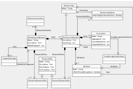
Figure 1 and figure 2 illustrate a practical example of a meta model that we have used to create a custom component architecture specification tool.
Figure 1- Meta-Model of a Component Specification Tool
In the example we are concerned with the capture of two types of components: Enter-prise Comp onents and Business Components.
Enterprise Components and Business Components can be stereotyped. For Enter-prise Components the stereotype can be used to indicate the market segment that the component is intended for. For Business Components the pre-defined list of stere o-types relates to the role of the component in the architecture such as <<Controller>> or <<Business Entity>>. If a need arises for further stereotypes these can be added to the meta model. The stereotypes are important, as they provide key information for the automatic generation of architectural plumbing and framework glue code.
We allow different types of associations between Business Components: simple association, aggregation, and containment—each of which has the semantics as de-fined in the UML. How these semantics are interpreted within the architecture in terms of object instantiation and retrieval from the database is specified in template code.
Component specifications consist of two parts: an informal part and an informal part. The informal part is intended for use by business analysts to list the responsibili-ties of components in plain English. The formal part is intended for use by a designer or developer to translate the responsibilities into component interface operations.
For the automatic generation of simple user interfaces and related data retrieval code, we allow business analysts to capture the visual recognition of Business Co m-ponents. The visual recognition of a business entity is defined as the set of properties that an end user would typically use to identify an object on the user interface. Note that we have defined visual recognition in such a way that not only attributes from a Business Components can be selected as part of visual recognition, but also attributes from directly related Business Components.
The Enterprise Interface is specified as a set of operations of an Enterprise Comp o-nent. The Application Interface(s) of an Enterprise Component are specified by tag-ging the relevant operations of the Business Components within an Enterprise com-ponent with "isPartOfApplicationInterface".
Business Components are part of an Enterprise Component. The aggregation rela-tionship used is not containment, i.e. there is no lifetime-dependency between aggre-gate and the part, which means that as part of a refactoring a Business Component may be reallocated to a different Enterprise Component.
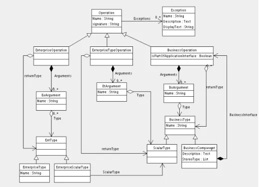
Figure 2- Meta-Model of a Component Specification Tool - Operations Enterprise Operations and Business Operations are allowed to use basic Data Types in their signatures. In addition to basic Data Types, Enterprise Operations are only al-lowed to use Enterprise Types in their signatures. Similarly, In addition to basic Data Types, Business Operations are only allowed to use Business Types in their signa-tures. All operations allow the specification of exceptions.
5.2 Model-to-Text Transformations
The main use of today's MDATM tools lies in their template language features, which allow the templatization of architectural code. Representing all transformations re-quired to map from a high level platform independent model to platform specific imple-mentation code in the form of code templates is not necessarily elegant, but it is
prac-tical and achieves the desired objective of keeping the platform independent model free from implementation details. As we show in [3], this technique leads to significant productivity improvements over hand coding or over skeleton code generation as provided by traditional UML tools. From a practical perspective, once an organization has invested in MDATM technology, there is no reason not to adopt an MDATM ap-proach, even for small projects. The use of MDATM tools makes economic sense in case a company needs to develop several applications for one target platform and also in case a company needs to implement one application on a range of target platforms.
5.3 Model-to-Model Transformations
To our knowledge none of the current MDATM tools provides good support for model-to-model transformations, which are needed to transform a PIM into a PSM. Currently we are on the verge of seeing a repetition of what happened to CASE tools a decade earlier. One can only hope that the OMG's MOF 2.0/QVT initiative [17] makes rapid progress towards the standardization of model transformations. Most tools proceed straight from a PIM to textual source code via a template language, and the large "gen-eration gap" leads to less than elegant template code. The Generative Model Trans-former (GMT) Open Source initiative [13] is an attempt to fill the gap and to push for-ward the MOF 2.0/QVT standardization effort. GMT already provides a highly scalable Open Source model-to-text transformation tool that can be used as an alternative to commercial MDATM tool offerings.
5.4 Impact of MDATM Tools on Software Development Teams
Software development teams are usually conservative when it comes to the introduc-tion of yet another tool into the development process. Practical demonstraintroduc-tions and concrete metrics such as provided in [3] are required to overcome skepticism from technically oriented resources. Interestingly, the more successful the demonstration of the superiority of a model-driven approach, the greater the potential for further difficulties down the road.
As we have outlined in [5], software developers try to keep up with constantly changing implementation technologies, and largely derive their personal market value from their knowledge of implementation technologies. Most software developers con-sciously only invest in skills that they perceive as increasing their marketability, i.e. mainstream implementation tools and technologies. Using a highly automated and domain-specific development environment that shields from many of the underlying technologies falls outside their field of interest, even if it would be beneficial to their employer. It is interesting to see how little emphasis most software engineers place in their CVs on their knowledge of specific business domains, and in most cases indeed business domain knowledge is not very deep. There is no easy solution to this situa-tion. A carefully planned and executed roll-out of MDATM can help alleviate unjusti-fied fears. In the longer term both employers and software developers need to realize the importance of domain knowledge, and need to recognize that only a limited number
of resources with deep skills in the "implementation technologies of the day" will be required in the future.
6 Lessons to Learn from Software Product Line Methodologies
Software Product Line Engineering consists of two parts:
• Domain Engineering (development of the product line architecture)
• Application Engineering (assembly of customer solutions from the product line) It is this distinction of two separate primary workflows that differentiates other soft-ware development methodologies from softsoft-ware product line engineering methodolo-gies. A similar distinction can be made between infrastructure development and appli-cation development in normal, non-product-line software development. All too often, software development resources are viewed as interchangeable by senior manage-ment, sometimes with disastrous effects when new development teams are assembled.
In our experience it is worthwhile to differentiate the skill set required for infrastruc-ture development from the skill set required for application development. Here we come back to the analogy of layers of components in software architecture with layers of components in the HiFi domain. The person designing the user interface of an am-plifier typically has a somewhat different skill set from the one designing a transistor. In the world of software, the lack of emphasis on relevant domain knowledge fre-quently leads to resources working outside their area of expertise. When assembling a software development process for a specific project, the individual skill sets and the domain experience of the available resources need to be a primary consideration. Fur-ther details on this topic can be found in [11].
Another important lesson from software product line engineering relates to archi-tectural software design. In most non-product line project scenarios, software architec-ture is driven primarily by implementation technology concerns, and only little atten-tion is being paid to the impact that variabilities and commonalities of the applicaatten-tion domain may have on the ability to build a durable software architecture. Domain analysis can add significant value even in a non-product-line context [10].
In summary, product line engineering methodologies such as FAST [20] and KobrA [1] have a lot to offer when combining the use of component-based development and MDATM tools. In comparison, the Rational Unified Process framework provides very little guidance, and also the agile methodologies largely fail to distinguish between infrastructure and application development.
7 How Agile Techniques fit into the Picture
Highly automated software development and the principles of the Agile Alliance don't have to be exclusive. Using tools such as model-driven generators naturally leads to agile application engineering, opening up possibilities of domain exploration to
appli-cation engineers that would be completely impractical in traditional, manually driven software development. Using advanced application engineering environments allows reacting to user requirements changes within days rather than months, allows short-ening iteration times, and speeds up the user feedback cycle.
Even after subtracting all the hype currently surrounding agile software develop-ment, there is still significant value in the agile principles. However we don't believe that any one of the currently documented agile methodologies provides a one-fits-all solution for all small-scale development projects. From this perspective Alistair Cock-burn [11] adopts a very pragmatic and honest standpoint, and negates the existence of a silver bullet methodology.
What can agile methodologies bring to the table that can be adapted for larger pro j-ects? One can argue that the four core values of the agile manifesto are useful and beneficial even in large projects, and that only the larger the project, the harder it be-comes to define a methodology that still is consistent with the core values.
Based on personal experience, intensive on-site customer involvement, short time-boxed iterations with end-user validation workshops, and a structured approach for extensive scope trading are essential for projects of all sizes. Taken together, these techniques can be summarized as "customer-driven product development". Timeboxes of about four-week duration have proved useful in practice. Once a basic infrastruc-ture has been developed, even substantial projects should be able to accommodate a cycle of four-week timeboxes.
Depending on whether a project is one-of-a-kind or product development for a set of customers, the structure of end-user validation workshops and scope trading work-shops at the end of a timebox needs to be adapted. In a geographically distributed setting it becomes necessary to host separate validation workshops with several dif-ferent groups of customers, and to resort to electronic workshop formats. The tech-niques described above can be used to reduce the risk exposure and turn around those projects where customer confidence has plummeted due to project delays and low quality, and where the relationship to the customer has already suffered.
7 Conclusions
Specification of a process to select and assemble process components into a method-ology for a specific context is not a simple matter. Even software development ap-proaches expressed as methodology frameworks such as the RUP fail to provide prac-tical instructions on how instantiate a concrete methodology. It is simplistic to think that the software industry will remain one industry with one set of best practices. The emerging concept of domain-driven design and development indicates that the soft-ware industry is slowly evolving into a set of specialized industries that are related, but where each industry has its own set of best practices. In order to classify the software industries, we suggest to start by applying domain analysis techniques to carve out the commonalities and variabilities.
References
1. Atkinson, C., Bayer, J., Bunse, C., Kamsties, E., Laitenberger, O., Laqua, R., Muthig, D., Paech, B., Wuest, J., Zettel, J.: Component-based Product Line Engineering with UML. Addison-Wesley, Component Software Series, (2002)
2. Beck, K.: Extreme Programming Explained: Embrace Change. Addison-Wesley, (2000) 3. Bettin, J.: Measuring the Potential of Domain-Specific Modeling Techniques. Proceedings of
the Second Domain-Specific Modeling Languages Workshop, OOPSLA, Working Papers W-334. Helsinki School of Economics, (2002), 39-44,
http://www.cis.uab.edu/info/OOPSLA-DSVL2/Papers/Bettin.pdf
4. Bettin, J.: A Language to Describe Software Texture in Abstract Design Models and Imple-mentation. Computer Science And Information Systems Reports TR-26, OOPSLA Work-shop on Domain-Specific Visual Languages. University of Jyväskylä, (2001), 1-9, http://www.isis.vanderbilt.edu/OOPSLA2K1/Papers/Bettin.pdf
5. Bettin, J.: Practical Use of Generative Techniques in Software Development Projects: an Approach that Survives in Harsh Environments. OOPSLA Workshop on Generative Pro-gramming, (2001), http://www.softmetaware.com/practicaluseofgenerativetechniques.pdf 6. Bosch, J.: Design & Use of Software Architectures, Adopting and Evolving a Produt-Line
Approach. Addison-Wesley, (2000)
7. Brown, A..: Large-Scale Component-Based Development. Prentice Hall, Object and Compo-nent Technology Series, (2000)
8. Cheesman, J., Daniels, J.: UML Components, A Simple Process for Specifying Component-Based Software. Addison-Wesley, Component Software Series, (2001)
9. Clauss, M.: Generic Modeling using UML extensions for variability. Computer Science And Information Systems Reports TR-26, OOPSLA Workshop on Domain-Specific Visual Lan-guages. University of Jyväskylä, (2001), 11–18
10. Cleaveland, J.C.: Program Generators with XML and Java. Prentice Hall, (2001) 11. Cockburn, A.: Agile Software Development. Addison-Wesley, (2001)
12. Cockburn, A.: Surviving Object-Oriented Projects. Addison-Wesley, (1998) 13. Generative Model Transformer. http://www.eclipse.org/gmt/
14. Highsmith, J.: Agile Software Development Ecosystems. Addison-Wesley, The Agile Soft-ware Development Series, (2002)
15. Mitchell, R., McKim, J.: Design by Contract, by Example. Addison-Wesley, (2002) 16. Jacobson, I., Booch, G., Rumbaugh, J.: The Unified Software Development Process.
Addison-Wesley, Object Technology Series, (1999)
17. Object Management Group: “Request For Proposal: MOF 2.0/QVT”, OMG Document, ad/2002-04-10. (2002)
18. Pree, W., Fontoura, M., Rumpe, B.: Product Line Annotations with UML-F. Lecture Notes in Computer Science, Vol. 2379. Springer-Verlag, Berlin Heidelberg New York, (2002), 188– 197
19. Reussner, R. CoCoNuts.
http://www.dstc.monash.edu.au/staff/ralf-reussner/coconuts/coconuts.html
20. Weiss, D., Lai, C.T.R.: Software Product Line Engineering, A Family-Based Software De-velopment Process. Addison-Wesley, (1999)