Parallel Integrity Testing
of Small Venting Filters
turning science
into solutions
Application
Note
Integrity
Testing
Dr. Jens Meyer Product Manager
Gas Filtration & Integrity Testing
Introduction
Sterilizing grade venting filters are used to avoid the potential risk of air-borne germs contaminating containers like fermentors or cell-culture vessels. Sterilizing grade filtration can only be guaranteed when the filters used are tested for integrity. There-fore, such filters are routinely tested by the bubble point or similar tests. Depending on the program settings and the actual bubble point (BP), it can easily take 10 – 20 min to perform one such test. When a large num-ber of filters are used and tested every day, it makes sense to think about how to make the test procedure more efficient without increasing the risk of overlooking defective filters.
This article describes a method by which Midisart venting filters can be tested efficiently by means of parallel testing. This parallel testing method drastically reduces the time required for testing, in turn yielding a clear economic benefit for users without compromising safety.
Method
How to Perform Bubble Point Tests Using the Parallel Method
Small venting filters of the type Midisart 2000 with a pore size of 0.2 μm and an effective filtration area of 20 cm2were used for this investigation. To prove their ability for detecting a single defective filter within an array of 10 filters in a parallel arrangement, one filter of pore size 0.2 μm was replaced with a filter with pore size 0.45 μm. The theory behind this set up was that, although the 0.45 μm filter was perfectly intact and within specification for 0.45 μm filters, it should not pass the integrity test run on bubble point limit values for 0.2 μm filters. If this theory applied, the question would then be to determine if it is possible for an automatic integrity tester to reliably detect the out-of-specification Midisart between the 0.2 μm standard filters.
An essential prerequisite for performing bubble point tests is that the membrane is wetted completely with a suitable wetting liquid. Because the PTFE membrane of the Midisart filters is extremely hydrophobic and not spontaneously wettable by water, a 60 % mixture of isopropyl alcohol (IPA)-water-mixture was used for wetting the membranes. To flush each filter with 20 ml of 60% IPA, a disposable syringe was used to apply the wetting solution in the direc-tion of filtradirec-tion. Because the testing pro-cedure forced wetting liquid out of the pores, any filters used for repeated testing were re-wetted in the same manner as described above to avoid any effect on the test results.
In the first step, the filters were wetted and then tested individually using the Sartocheck 4 automatic integrity tester. The test results were documented electronically and additionally printed out on paper.
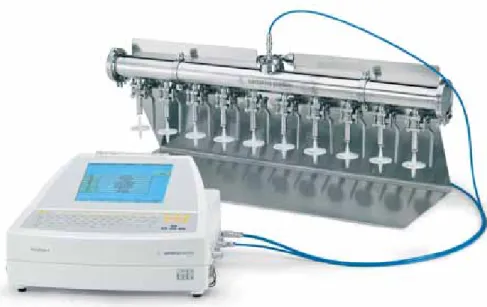
In the second step, the same filters were mounted on the Midisart manifold (figure 1) containing an array of 10 Midisarts and the manifold was subjected to a parallel bubble point test using the same test unit. The results were documented.
2
Figure 1:Test arrangement for parallel integrity testing of 10 Midisart venting filters.
To show that it is possible to detect a single defective filter amongst 9 others, one Midisart 2000 filter with pore size 0.2 μm (min BP = 1.4 bar) was replaced with a Midisart 2000 filter with pore size of 0.45 μm (min BP = 0.9 bar) as described above. Then, the complete manifold with 9 intact plus one assumedly “defective” filter was tested. Although the 0.45 μm filter was intact, it should theoretically be identified as defective within the specifica-tion for the 0.2 μm filters (BP < BPmin).
The stabilization time was set to 5 min and a minimum BP of 1.4 bar was programmed. Before testing all filters separately as described above, the test series was started with a leakage test to prove the validity of the complete test setup. For this purpose, all valves of the test manifold were closed and a pressure hold test (P = 2 bar, t = 5 min.) was run with the integrity tester Sartocheck 4. The pressure was kept pretty stable during the test without any signs of leakage. Individual Tests 0 10 20 30 40 50 60 70 1000 1100 1200 1300 1400 1500 1600 1700 1800 Pressure [mbar] Flow [mL/min] BPmin 0,45 µm 0,2 µm
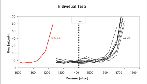
Figure 2:Test results of the bubble point tests for individual Midisart filters. Each curve represents the measurement of a single filter. 10 Midisart 2000 filters with a pore size of 0.2 μm (black curves) and one Midisart with a pore size of 0.45 μm (red curve) were tested.
Results
An average bubble point of 1.69 ± 0.025 bar was found for the 0.2 μm Midisart filter, while the 0.45 μm version had a signifi-cantly lower BP of 1.23 bar (figure 2). This meant that the 0.45 μm filter failed the test as soon as the BP limit (BP min) for the 0.2 μm filter was used as test criterion.
4
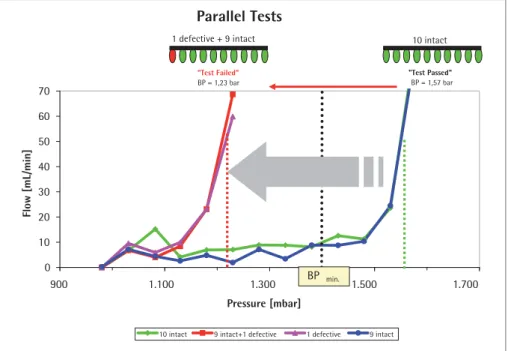
The parallel test of the 10 "intact“ Midisarts resulted in a BPallof 1.57 bar (figure 3).
This value correlate nicely with the BP values measured for the individual filters. The measured BP of the parallel test was slightly lower compared to the BP of indi-vidual tests due to the fact that the flow through the 10 filters is higher which then consequently leads to an earlier detection of the BP criterion. The test was classified as “test passed” and therefore all 10 filters showed integrity.
In the next step where one "intact“ Midisart was replaced with the "defective“ filter (0.45 μm) and the array of the 10 filters (9 “intact” plus 1 “defective” with a low BP) was subjected to a BP test at the identical
Parallel Tests 0 10 20 30 40 50 60 70 900 1.100 1.300 1.500 1.700 Pressure [mbar] Flow [mL/min]
10 intact 9 intact+1 defective 1 defective 9 intact
"Test Passed" BP = 1,57 bar "Test Failed" BP = 1,23 bar 10 intact 1 defective + 9 intact i t t BP min.
Figure 3:Test results of parallel bubble point tests of 10 filters arranged on the Midisart test manifold. Substituting one intact filter for a "defective" one (0.45 μm pore size) led to a clear shift in the bubble-point curve and finally resulted in a failed test. The filter with the lowest BP also defined the BP when multiple filters were tested in parallel. Therefore, a single defective filter can be reliably detected within a multiple testing manifold.
test parameter settings, the test resulted in a BP of 1.23 bar and the test was classified as “test failed” (figure 3). The BP value of all 10 filters was clearly defined by the filter with the lowest BP (1.23 bar) which was the so-called "defective" one. This meant that the “defective” filter was successfully detected when 10 filters were measured in parallel.
To confirm this result, the defective filter was pneumatically decoupled by closing the connected valve and the remaining 9 intact Midisarts were retested after re-wetting. This test resulted in a BP of 1.57 bar, i.e. it was identical to the test result obtained when all 10 "intact" filters were tested.
Discussion
The Bubble Point Test
The bubble point is defined as the pressure at which the wetting liquid is forced out of the pores, thereby creating bubbles. By increasing the pressure on the upstream side, the differential pressure increases and finally overcomes the capillary forces to consequently press water out of the pores of the filter.
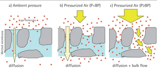
Figure 4:When a differential pressure is applied across a completely wetted membrane, the pores are blocked and only low quantities of gas molecules have the chance to pass the membrane by diffusion. When the differential pressure exceeds the bubble point, the wetting liquid is forced out of the biggest pores, leading to an over-proportional increase of air flow. This behaviour is used for identifying the BP of a membrane. Wett ed membrane c) Pressurized Air (P≥BP) b) Pressurized Air (P<BP) diffusion a) Ambient pressure gas molecules
diffusion diffusion + bulk flow
Below the bubble point pressure, only dif-fusive flow through the wetted pores takes place. In that situation the amount of dif-fusive flow is relatively low, and a linear relationship exists between test pressure and air flow rate. When the test pressure is increased incrementally to the bubble point, the air flow starts to increase over-proportionally because diffusive flow occurs at this point in parallel with bulk flow through opened pores. This bulk flow is much bigger than the diffusive flow and can be used to detect the bubble point. In principle, the automatic integrity tester checks the air flow by measuring the
pressure decay in the filter housing on the upstream side of the filter. The test pres-sure is increased in increments of 50 mbar and the air flow rate is measured for each step. The resolution of the bubble point measurement is limited by the size of the increment (±50 mbar) but can also be adjusted when higher accuracy is required or test time should be shortened. The test device determines the point of over-pro-portional increase of the air flow using internal algorithms. This correlates with the point where the first pores open and enhanced flow starts. The integrity tester uses this pressure as the bubble point.
The bubble point therefore reflects the pore size of the largest pores within the membrane, namely because the pores with the largest pore diameter offer the lowest capillary forces and the liquid is removed more easily than through smaller-diameter pores.
This fact makes sense because exactly those large pores offer a risk for micro-organisms to pass the membrane, which consequently would lead to product contamination. It should be mentioned here that the bub-ble point per se does not tell anything about the retention capabilities of the membrane, but is only a robust physical test. To determine the retention capability of a filter, sophisticated microbiological tests must be performed and correlated with the results of the integrity tests. Such tests are performed by the filter manufac-turers during filter validation and for the purpose of quality checks. Filters have to
6
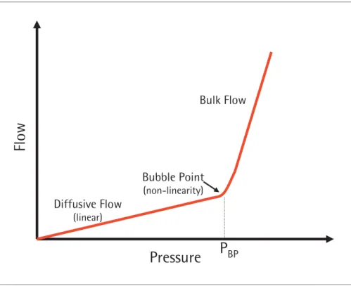
Figure 5:Air flow curve plotted for a wetted membrane during a standard bubble point test.
At the bubble point, the curve starts to be non-linear due to the enhanced air flow through opened pores.
Pressure
Flow
Diffusive Flow
(linear)Bulk Flow
Bubble Point
(non-linearity)P
BPpass the bacterial challenge test (BCT) which means they must be able to produce a sterile filtrate after filtering a test solu-tion containing 107bacteria (Brevundi-monas diminuta) per cm2filter area (HIMA document No. 3, VoP. 4, 1982). The limit value (BP min) is defined when correlating the test result of the BCT (test passed or failed) with the BP of the same filter and adding a specific safety margin.
As soon as the BP of a filter drops below the limit value (BP min), sterile filtrate or sterile air filtration cannot be guaranteed. Consequently, such filters may not be used in pharmaceutical production process. The facts discussed above underline the critical importance of filter integrity testing within biopharmaceutical production processes. Therefore, it is necessary to reliably detect defective filters within a multiple-filter arrangement and parallel integrity testing.
Identification of Defective Filters
Obviously, a failed filter integrity test does not identify which of the parallel tested filters is the defective one. Consequently, all 10 filters have to be tested individually to achieve safety.
The Midisart test manifold was designed to allow a different approach. Short tubes can be connected to the hose barbs of the filters and the other end can be hung in a water bath. The bubble point test is started and the test pressure is reached; the diffu-sion-driven air flowing through the wetted membrane causes the air bubbles to come out of the tube slowly. As illustrated above, the bubble point is characterized by a disproportionate increase in air flow. This sudden increase in flow can be visualized by a sudden increase in air bubbling out of the tube. A defective filter reaches the BP earlier and can be identified simply by observing the air bubbles that leave the different tubes. As soon as the defective filter is identified, it can be pneumatically decoupled from the manifold by closing the valve and the remaining 9 filters can be tested afterwards. The parallel procedure avoids all 10 filters having to be tested individually.
In this context, it is important to note that a failed test does not automatically mean that a filter is really defective. When filters repeatedly fail integrity testing, the correct wetting of the membrane should be checked. A membrane that is not perfectly wetted will definitely fail the test although the membrane itself is functioning properly within its sterilizing grade. In such a case, the wetting procedure should be improved and the test repeated.
Conclusion
In conclusion, the data presented above clearly show that a single defective filter reliably leads to a failed integrity test when tested in a multiple arrangement together with 9 intact filters. The relatively small filtration area of 20 cm2produces a low diffusion rate for the single elements. In this situation, the masking effects common with larger (pleated) filter elements play a negligible role. When more than one filter is tested for integrity, the filter with the lowest bubble point determines the BP of the multiple filter arrangement. This observation underlines the safety of paral-lel testing such small filters and proves that a defective filter will lead to a failed test. The time required for the testing procedure can thereby be reduced by 90 %. This allows more filters to be tested in a given time frame which generates an economic benefit for users.
Sales and Service Contacts
For further contacts, visit www.sartorius-stedim.com
Europe
GermanySartorius Stedim Biotech GmbH August-Spindler-Strasse 11 37079 Goettingen Phone +49.551.308.0 Fax +49.551.308.3289 www.sartorius-stedim.com Sartorius Stedim Systems GmbH Schwarzenberger Weg 73–79 34212 Melsungen Phone +49.5661.71.3400 Fax +49.5661.71.3702 www.sartorius-stedim.com France
Sartorius Stedim Biotech S.A. Z.I. des Paluds
Avenue de Jouques – BP 1051 13781 Aubagne Cedex Phone +33.442.845600 Fax +33.442.845619
Sartorius Stedim France SAS ZI des Paluds Avenue de Jouques – CS 71058 13781 Aubagne Cedex Phone +33.442.845600 Fax +33.442.846545 Austria
Sartorius Stedim Austria GmbH Franzosengraben 12 A-1030 Vienna Phone +43.1.7965763.18 Fax +43.1.796576344
Belgium
Sartorius Stedim Belgium N.V. Leuvensesteenweg, 248/B 1800 Vilvoorde Phone +32.2.756.06.80 Fax +32.2.756.06.81
Denmark
Sartorius Stedim Nordic A/S Hoerskaetten 6D, 1. DK-2630 Taastrup Phone +45.7023.4400 Fax +45.4630.4030
Italy
Sartorius Stedim Italy S.p.A. Via dell’Antella, 76/A
50012 Antella-Bagno a Ripoli (FI) Phone +39.055.63.40.41 Fax +39.055.63.40.526
Netherlands
Sartorius Stedim Netherlands B.V. Edisonbaan 24
3439 MN Nieuwegein Phone +31.30.6025080 Fax +31.30.6025099
Spain
Sartorius Stedim Spain SA C/Isabel Colbrand 10–12, Planta 4, Oficina 121
Polígono Industrial de Fuencarral 28050 Madrid
Phone +34.91.3586102 Fax +34.91.3588804
Switzerland
Sartorius Stedim Switzerland GmbH Lerzenstrasse 21
8953 Dietikon Phone +41.44.741.05.00 Fax +41.44.741.05.09
U.K.
Sartorius Stedim UK Limited Longmead Business Park Blenheim Road, Epsom Surrey KT19 9 QQ Phone +44.1372.737159 Fax +44.1372.726171
America
USASartorius Stedim North America Inc. 5 Orville Drive
Bohemia, NY 11716 Toll-Free +1.800.368.7178 Fax +1.631.254.4253 Sartorius Stedim SUS Inc. 1910 Mark Court Concord, CA 94520 Phone +1.925.689.6650 Toll Free +1.800.914.6644 Fax +1.925.689.6988 Sartorius Stedim Systems Inc. 201 South Ingram Mill Road Springfield, MO 65802 Phone +1.417.873.9636 Fax +1.417.873.9275
Argentina
Sartorius Argentina S.A. Int. A. Avalos 4251 B1605ECS Munro Buenos Aires Phone +54.11.4721.0505 Fax +54.11.4762.2333 Brazil
Sartorius do Brasil Ltda Av. Dom Pedro I, 241 Bairro Vila Pires Santo André São Paulo Cep 09110-001 Phone +55.11.4451.6226 Fax +55.11.4451.4369 Mexico
Sartorius de México S.A. de C.V. Circuito Circunvalación Poniente No. 149 Ciudad Satélite
53100 Naucalpan, Estado de México Phone +52.5555.62.1102 Fax +52.5555.62.2942
Asia | Pacific
ChinaSartorius Stedim Beijing Representative Office No. 33, Yu’an Road,
Airport Industrial Zone B, Shunyi District Beijing 101300
Phone +86.10.80426516 Fax +86.10.80426580 Sartorius Stedim Shanghai Represantative Office
Room 618, Tower 1, German Centre, Shanghai, PRC., 201203
Phone +86.21.28986393 Fax +86.21.28986392.11 Sartorius Stedim Guangzhou Office Room 704, Broadway Plaza, No. 233–234 Dong Feng West Road Guangzhou 510180
Phone +86.20.8351.7921 Fax +86.20.8351.7931
India
Sartorius Stedim India Pvt. Ltd. 10, 6th Main, 3rd Phase Peenya KIADB Industrial Area Bangalore – 560 058 Phone +91.80.2839.1963|0461 Fax +91.80.2839.8262
Japan
Sartorius Stedim Japan K.K. KY Building, 8–11 Kita Shinagawa 1-chome Shinagawa-ku Tokyo 140-0001 Phone +81.3.3740.5407 Fax +81.3.3740.5406
Malaysia
Sartorius Stedim Malaysia Sdn. Bhd. Lot L3-E-3B, Enterprise 4 Technology Park Malaysia Bukit Jalil
57000 Kuala Lumpur Phone +60.3.8996.0622 Fax +60.3.8996.0755
Singapore
Sartorius Stedim Singapore Pte. Ltd. 10, Science Park Road, The Alpha #02-25, Singapore Science Park 2 Singapore 117684
Phone +65.6872.3966 Fax +65.6778.2494
Australia
Sartorius Stedim Australia Pty. Ltd. Unit 5, 7-11 Rodeo Drive Dandenong South Vic 3175 Phone +61.3.8762.1800 Fax +61.3.8762.1828
Specifications subject to change without notice. Printed in Germany on paper that has been bleached without any use of chlorine
. W · G.