Microjet array single-phase and flow boiling heat transfer with R134a
Eric A. Browne
a, Gregory J. Michna
b, Michael K. Jensen
a, Yoav Peles
a,*a
Mechanical, Aerospace, and Nuclear Engineering, Rensselaer Polytechnic Institute, Troy, NY 12180, USA b
Department of Mechanical Engineering, South Dakota State University, Brookings, SD 57007, USA
a r t i c l e
i n f o
Article history: Received 15 March 2010
Received in revised form 10 July 2010 Accepted 10 July 2010 Keywords: Microjet Jet array Impingement Flow boiling
a b s t r a c t
An experimental study of single-phase and flow boiling heat transfer of a submerged microjet array was conducted with R134a. The staggered array of seventeen 112-lm diameter orifices impinged onto a 11-mm heater. Single-phase data were gathered over the range 30506Red610,600 with 53:66Nud6128. Boiling experiments were conducted with liquid subcoolings of 10, 20, and 30°C at jet velocities of 4, 7, and 10 m/s. Boiling was generally found to enhance heat transfer with a maximum heat flux of 590 W/cm2. However, temperature excursions occurred at low superheats and were found to
be related to non-condensable gas content.
Ó2010 Elsevier Ltd. All rights reserved.
1. Introduction
Electronic devices are dissipating increasing heat loads from shrinking footprints, so cooling techniques more effective than forced air convection will be required. Single-phase flow and flow boiling in microchannels have been extensively studied[1–3] to address this cooling need. However, one potentially more effective method that has not been extensively studied to date is jet impingement cooling. Macroscale jets have been studied[4–10]
with a variety of fluids and flow schemes and have been used to cool turbine blades and quench metals. Many of these practical uses of jets employ an array of jets rather than a single impinging jet, because arrays of jets typically maintain a more consistent sur-face temperature and can cool larger areas than a single jet. Jet ar-rays have been studied[7,8,11–17]and require several parameters to define their geometry, which affect heat transfer performance.
Limited microscale studies have recently been conducted[18– 23]to investigate the effects of scale on performance, including a potential scale enhancement. A previous study by the authors
[24] has shown that high (400,000 W/m2K) area-averaged heat transfer coefficients and heat fluxes exceeding 1100 W/cm2 can be attained with an array of single-phase water microjets.
Regardless of this high performance, water is generally consid-ered incompatible with electronics; therefore, a fluid that can come into contact with electronics without causing damage is required for use in electronics cooling. Various refrigerants are often se-lected for this purpose, with a popular choice being R134a.
Unfor-tunately, the heat transfer properties of R134a are inferior to water. As a result, area-averaged heat transfer coefficients are low-er than those for watlow-er undlow-er the same flow conditions. Howevlow-er, boiling has been used to enhance heat transfer and may allow high heat removal rates while still using an electronics-compatible fluid. Boiling jet studies have been performed[25–30]but mostly with single jets. This study employs an array of submerged circular microjets of diameter 112
l
m on a 11 mm heater to investigate single-phase and boiling heat transfer with R134a.2. Experimental apparatus and method 2.1. Experimental apparatus
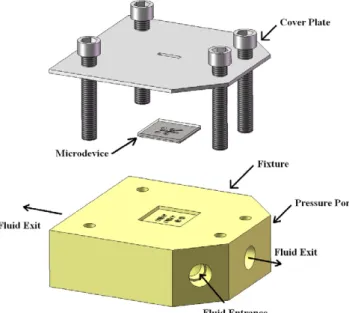
A closed-loop system (Fig. 1) with a custom built fixture (Fig. 2), which housed a microdevice (Fig. 3) with an array of microjets and a thin-film heater, was used to experimentally study heat transfer with impinging microjets. The flow rate in the system was set with a gear pump and a bypass with a needle valve, which provided fine flow rate control; a turbine flow meter measured the flow rate. A bladder accumulator controlled the pressure in the loop. Pre-scribed inlet temperatures were achieved with a constant temper-ature bath pumping coolant through a concentric tube heat exchanger and with a separate electrical pre-heater. Inlet temper-ature and pressure were measured just prior to the fixture, and pressure was measured in the microdevice. The fixture was placed under a microscope equipped with a high-speed camera for flow visualization.
The microdevice was seated into a pocket that was machined into the top face of the fixture. In that pocket were seats foro-rings,
0017-9310/$ - see front matterÓ2010 Elsevier Ltd. All rights reserved. doi:10.1016/j.ijheatmasstransfer.2010.07.062
* Corresponding author. Tel.: +1 518 276 2886; fax: +1 518 276 2623. E-mail address:pelesy@rpi.edu(Y. Peles).
Contents lists available atScienceDirect
International Journal of Heat and Mass Transfer
j o u r n a l h o m e p a g e : w w w . e l s e v i e r . c o m / l o c a t e / i j h m twhich were used to create multiple seals with the microdevice. Electrical contact was made with two gold coated, sprung pins that were press-fit into the fixture. The device was clamped into place with an aluminum plate, which had a slot cut into it such that visu-alization could be carried out.
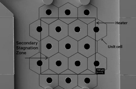
Fluid entered the microdevice through the microjet array (Fig. 4), which had 17 jets of diameter 112
l
m, spaced 360l
m cen-ter-to-center in an equilateral triangle to form a hexagonal array. The array was placed on the bottom of a chamber, and the jets im-pinged onto a thin-film 11-mm heater on the top face of the chamber that was 10-mm long, 2-mm wide, and 200-l
m tall. Fluid exited this chamber through two round 1-mm holes at either end. A direct current power supply provided the power for the hea-ter. Two digital multimeters measured the heater current and volt-age drop for use in calculations. Experimental measurements were recorded with LabView and National Instruments data acquisition hardware.2.2. Microfabrication
The microdevice was fabricated using standard microelectro-mechanical systems procedures in a cleanroom. The device was
largely composed of two bonded wafers, an etched silicon wafer, and a pyrex wafer with patterned thin-films. The 11-mm heater was 100-nm thick titanium and was connected to 1-
l
m aluminum vias. The microdevice in this study was fabricated similarly to de-vices fabricated for a previous study[24](details of the microfab-rication are discussed in this earlier paper).2.3. Experimental procedures
The thin-film heater in the microdevice was used to measure average surface temperature in addition to providing a constant heat flux boundary condition. The heater was calibrated as a resis-tive temperature device in an oven with a thermocouple attached to the microdevice from 25 to 100°C in 5°C increments. A third-order polynomial was then fit to the data. The turbine flow meter was calibrated for R134a using the weigh tank approach.
Conductive heat losses from the heater were quantified by installing the device in its fixture and evacuating the loop to pre-vent natural convection. Conductive heat losses were then corre-lated to the heater temperature for use in heat loss estimation covered in more detail in Section2.4. The system was then charged with R134a for experiments.
Nomenclature
Aheater surface area of the heater
Ar area ratio
d diameter of jet orifices
H standoff (distance from orifice exit to heater surface)
h area-averaged convective heat transfer coefficient k thermal conductivity of the working fluid
kSiO2 thermal conductivity of the silicon oxide covering the heater
L heater length
Nud area-averaged Nusselt number based on jet diameter
Pchamber chamber pressure
q00 surface heat flux
Qheater total power supplied to the heater
Qloss heat loss from heater other than convection directly to fluid
Red Reynolds number based on jet diameter tSiO2 thickness of silicon oxide covering the heater Th average heater temperature
Ts average surface temperature Tin fluid inlet temperature V average jet exit velocity Greek symbols
DTsat surface super heat
l
dynamic viscosityq
densityTo achieve the desired inlet conditions, the flow rate, pre-hea-ter power, and thermal bath temperature were set for a given jet velocity and inlet subcooling with no power applied to the hea-ter. Once the system reached the appropriate steady state with respect to inlet conditions, power was applied to the heater. Data were recorded after the heater temperature reached steady state; however, this occurred rapidly (within 100 ms) as the thermal inertia of the heater was small. To trace a boiling curve, the heater power was incremented, starting in the single-phase region, until an increase in power resulted in a non-steady tem-perature excursion. The average surface temtem-perature ranged from the fluid inlet temperature, at low power, to around 10 or 15°C superheated when the temperature excursions occurred. The flow rates used in the study were bounded by the range of the flow sensor, and resulted in jet velocities of 4, 7, and 10 m/s. Single-phase data were also taken at steady state, but over a range of Reynolds numbers. Data were gathered using an inlet temperature of about 20°C and an average surface temperature of about 50°C. The surface was subcooled by 15°C throughout the single-phase experiments.
2.4. Heat losses
Estimates of the upper and lower bounds of the heat losses in this experiment were made by combining the results of a numeri-cal analysis and a conduction loss experiment. The experimental heat loss was then taken to be the average of the two bounds with half the difference of the two as the uncertainty in the heat loss. This procedure was used by the authors in a previous study[24]
and was described in detail in that paper. The maximum heat loss during the flow boiling experiments ranged from 24% to 4.8% depending on the flow velocity and heat transfer coefficient. 2.5. Data reduction
Typically, jet studies use the jet Reynolds number defined as Red¼
q
Vdl
ð1Þwhere
q
is the density,Vis the average velocity at the orifice exit,d is the orifice diameter, andl
is the dynamic viscosity, with the ther-mophysical properties of the fluid evaluated at the film tempera-ture. The average orifice velocity was calculated usingV¼ m_
q
Nj pd24
ð2Þ
whereNjis the number of jets in the array, andm_ is the total system flow rate.
The area-averaged Nusselt number typically used in single-phase jet impingement literature is
Nud¼ hd
k ð3Þ
wherehis the area-averaged heat transfer coefficient andkis the conductivity of R134a. The area-averaged heat transfer coefficient was calculated using the inlet temperature and the surface temper-ature; the difference between the inlet temperature and jet exit temperature was negligible as the fixture was made from an insu-lating plastic.
However, these parameters are functions of physical properties. In boiling studies, the film temperature changes significantly with heat input from near the inlet temperature to potentially above the saturation temperature if the wall superheat exceeds the inlet
sub-Fig. 2.Exploded view of the microdevice and the fixture.
cooling. Therefore, boiling results are given in dimensional form with jet velocityV, surface heat fluxq00, and surface superheatDTsat. The heater current and voltage were used to calculate the total power dissipated by the heater. The heat dissipated from the hea-ter by single-phase convection and boiling was then found by sub-tracting the heat losses previously described. The heater current and voltage were also used to calculate the electrical resistance of the heater, which had been correlated to average heater temper-ature prior to experiments. However, the heat transfer surface was not the heater itself, but a 1-
l
m thick silicon oxide which covered the heater. The surface temperature (Ts) of the silicon oxide was calculated according to a one-dimensional conduction analysis that used the heat transfer though the oxide layer (QheaterQloss), the thickness of the thin-film (tSiO2), the area of the heater (Aheater), and the conductivity of the oxide (kSiO2) according to:Ts¼ThðQheaterQlossÞtSiO2 AheaterkSiO2
ð4Þ
The area-averaged heat transfer coefficient (h) was calculated from the total power dissipated from the heater (Qheater), the heat loss (Qloss), the surface temperature (Ts), the fluid inlet temperature (Tin), and the heater area (Aheater) using
QheaterQloss¼hAheaterðTsTinÞ ð5Þ The superheat (DTsat) of the heat transfer surface was calculated with the surface temperature (Ts) and the saturation temperature using
D
Tsat¼TsTsat ð6Þ2.6. Uncertainties
The propagation of uncertainties in the reduced data employed standard methods[31]. The uncertainty in the heat flux dissipated from the heat transfer surface was generally highest at low values ofDTsatbut did not exceeded 8.1%. The area-averaged heat transfer coefficient uncertainties were generally larger than the uncertainty in the heat flux due to the contribution from the uncertainty in sur-face temperature (±1°C). This was particularly true at the begin-ning of the flow boiling curves where the difference in jet and surface temperatures was only 2°C and the uncertainty in DT
was therefore roughly 50%. However, despite large uncertainties in the area-averaged heat transfer coefficient at low heat fluxes, the uncertainty was reduced to less than 9.9% for the data above 100 W/cm2. The maximum uncertainty in the single-phase, non-dimensional measure of heat transfer performance, area-averaged Nusselt number was 6.3%.
3. Results and discussion 3.1. Single-phase results
The single-phase heat transfer performance of this array with R134a is compared non-dimensionally (Fig. 5) with air and water data gathered in a previous study[32]. The exponent ofPr0.4is ta-ken as a general value from jet impingement literature and is not the result of experimental results analysis. The Prandtl numbers of R134a and water shown in the figure are in the range of 3 and 4, respectively; therefore, no strong conclusion about the effect of Prandtl number can be drawn. The air data shown inFig. 5
ran-Fig. 4.SEM of the microjet array with the heater edges and unit cells superimposed.
ged from an incompressible flow at low Reynolds number to a choked flow at and above Reynolds number equal to 2255, which may explain the increased deviation from the incompressible flows of water and R134a with increasing velocity. For the incompress-ible flows the data showed a consistent trend and were best fit by Nud
Pr0:4¼0:20Re 0:637
d ð7Þ
Due to the three fluids’ different thermophysical properties, their dimensional heat transfer performances varied significantly (Fig. 6). Water had the best performance with an area-averaged heat transfer coefficient of 318,000 W/m2K and dissipated 930 W/cm2at a pressure drop of 348 kPa and a temperature differ-ence of 29°C. The more appropriate electronics cooling fluid, R134a, had a peak area-averaged heat transfer coefficient of 90,700 W/m2K and dissipated 250 W/cm2at a lower pressure drop of 187 kPa and temperature difference of 28°C. Experiments with R134a were performed up to the maximum flow rate measureable in the apparatus. Larger flow rates, resulting in greater pressure drops, would improve performance, but water will continue to out-perform R134a in area-averaged heat transfer coefficient. 3.2. Flow boiling
3.2.1. Comparison with literature
Flow boiling data were gathered for jet velocities of 4, 7, and 10 m/s with inlet subcooling of 10, 20, and 30°C. The system pres-sure was fixed at 1240 kPa, which resulted in a saturation temper-ature of 47°C. The nine boiling curves are plotted inFigs. 7–9. The maximum heat flux dissipated was 335 W/cm2(Fig. 9) with 30
°C subcooling and a jet velocity of 10 m/s. Webb and Ma[9]used a similar fluid (R113) with a single submerged, horizontal jet and re-corded heat fluxes in the same range for lower values of subcooling and jet velocity. However, the experiments used two jet diameters, 1.07 and 1.81 mm, and two heater sizes 33 and 55 mm. The area ratio in that study ranged from 4.6% to 36% versus the 8.8% area ratio of the current array. For a single jet, the single-phase wall jet region will perform better at higher area ratios as the wall jet region will be shorter and the resulting boundary layer will be thinner. The greater single-phase contribution in the Webb and Ma
[9]experiments could be the reason for the better overall perfor-mance. Monde and Katto [27] also gathered boiling data with R113 but with a free 2-mm diameter jet and area ratios between 6% and 10%. Comparing their saturated boiling with the 10°C sub-cooled data in Fig. 10, the performance is generally similar, although the extent of the superheated region is smaller for the current study.
3.2.2. Surface superheat
It is important to note that the surface superheat was calculated with an average surface temperature. Local temperatures are un-known, which means that at saturation conditions (DTsat= 0), the parts of the surface with lower than average heat transfer coeffi-cients are superheated. However, visualization during the experi-ments confirmed that local superheat was not adequate to cause
Fig. 6.Dimensional single-phase heat transfer performance.
Fig. 7.Heat transfer data for an inlet subcooling of 10°C.
nucleation in the subcooled region (DTsat< 0°C). Boiling inception occurred in all cases after the average surface temperature ex-ceeded the saturation temperature of the fluid. Visualization showed that boiling typically began in secondary stagnation zones, which are points equidistant from three adjacent jets (Fig. 4) and areas of stagnation in the absence of crossflow. The secondary stag-nation zones are expected to have low heat transfer coefficients and, therefore, higher surface temperatures and thicker thermal boundary layers due to low velocity. With higher heat fluxes, the boiling spread along the edges of the hexagonal unit cells (Fig. 4), which denote a jet’s region of influence. The edge of a unit cell is also where the radial outflows from two adjacent jets meet in the absence of crossflow. The hexagonal shape of the unit cells was apparent in the visualization as it was occupied by vapor bubbles.
3.2.3. Area-averaged heat transfer coefficient
The area-averaged heat transfer coefficients are reported for the same experiments inFigs. 10–12. In the single-phase region, the area-averaged heat transfer coefficients are constant with respect to heat flux, and the data inFigs. 7–9are linear. After the onset of nucleate boiling (ONB), the heat transfer coefficient increases with increasing heat flux causing the boiling curves to bend up-ward. The heat transfer enhancement is due to nucleate boiling. The trend of increasing enhancement with increasing heat flux is likely due to some combination of increasing boiling area and increasing boiling heat transfer coefficients.
In previous single-phase jet impingement publications[10,17], the heat transfer domain was divided into the stagnation and wall jet regions. A weighted average of the two zones based on
geome-Fig. 9.Heat transfer data for an inlet subcooling of 30°C.
Fig. 10.Area-averaged heat transfer coefficients for 10°C inlet subcooling.
Fig. 11.Area-averaged heat transfer coefficients for 20°C inlet subcooling.
try yielded the area-averaged Nusselt number. This was done to capture the contributions of both zones which have different char-acteristics. For boiling jet arrays, it may be necessary to employ a third zone to account for boiling. However, the boiling zone size would be a function of several parameters, including heat flux, whereas the stagnation and wall jet regions have been divided by a static geometric value.
Boiling extended 15°C into the superheated wall region, which was less than other studies[25,27]. Data at higher wall superheats could not be taken due to temperature excursions. The tempera-ture excursions occurred under constant power after an increase in power and were manifested by ever increasing surface temper-atures. However, the temperature increase did not always occur rapidly. Initially, the change was slow, 2 or 3°C a minute, but be-came more rapid as time went on, reaching rates of 5°C per min-ute. Data were only taken when a steady state condition existed. Therefore, when the temperature increased monotonically after a step change in heat flux, the experiment was concluded. A temper-ature excursion concluded all experiments.
Estes and Mudawar[25]and Monde and Katto[27]used copper heaters which would have much larger conjugate effects than the thin-films used by Ma and Bergles [26] and the current study. However, it is still expected that the temperature measured at the jet centerline is a minimum and that the average surface tem-perature over an entire heater was higher. Therefore, in the com-parison of the current study with the aforementioned studies, the difference in heater temperature is likely even greater.
3.2.4. Hydrodynamics
Another important fact is that Monde and Katto[27]and Estes and Mudawar[25]used single free jets. With a free jet, a thin high velocity fluid film with a free surface, called the wall jet, is formed on the heater outside the stagnation zone. Under boiling condi-tions, bubbles nucleate starting at the edges of the heater where the film and the fluid is likely the hottest. As heat flux increases, nucleation becomes possible at sites closer to the stagnation zone, and the boiling zone grows inward. The vapor bubbles are ad-vected away from the heater by the fast radial wall jet. Estes and Mudawar [25] show surface superheats of around 40–60°C for three different flow rates and subcoolings.
In a submerged flow, viscous forces draw warmer ambient fluid into the jet before it reaches the impingement surface and slow the wall jet, as it no longer has a free surface, reducing the velocity of the wall jet and therefore, the drag on a surface bubble. In the cur-rent subcooled, submerged jet array boiling experiments, vapor bubbles nucleated at and traveled along unit cell boundaries to la-ter condense outside the heala-ter. In a jet array, the wall jet regions interact and do not necessarily constantly act to force a vapor bub-ble off the heater, but rather forces bubbub-bles to the edge of a unit cell. Because of the different vapor advection mechanisms, jet ar-rays may suffer critical heat flux at lower surface superheats than free jets, but the effect of jet condition on critical heat flux is unknown.
3.2.5. Temperature overshoot
No temperature overshoot normally associated with boiling inception was detected in this study. This may be due to the fact that the temperature measurement is an average over the entire heater which could have locally experienced temperature over-shoot. However, Ma and Bergles[26], in their study on a single macroscale jet of R113, found that temperature overshoot disap-peared at a jet velocity of 10 m/s.
3.2.6. Effect of subcooling
Increased subcooling shifted boiling curves to the left. At very low power it is expected that the surface would be very near the
inlet temperature, and, therefore, the first data point of any boiling curve will be near the inlet subcooling in terms of relative surface temperature. Since the area-averaged heat transfer coefficient is not a strong function of inlet temperature the single-phase portion of the curve is simply shifted. However, inlet subcooling did not have a strong effect on the superheat at which the temperature excursion occurred. The highest heat flux dissipated in the flow boiling curves for a given jet velocity increased with inlet subcooling.
3.2.7. Effect of jet velocity
In the single-phase region, heat transfer is achieved through forced convection alone, which is a function of jet velocity for a gi-ven inlet temperature. For this reason the boiling curves are or-dered by jet velocity within each of theFigs. 7–9. It is also clear fromFigs. 10–12that higher jet velocities resulted in higher sin-gle-phase heat transfer coefficients. The higher heat transfer coef-ficients required greater heat fluxes to achieve a given surface temperature, which also partially explains why boiling initiation heat flux increased with jet velocity.
3.3. Effect of a non-condensable gas
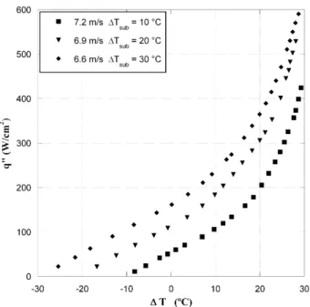
Prior to the collection of the data previously discussed, an experiment was performed before we identified a faulty bladder accumulator, which leaked nitrogen into the loop. During that experiment, this dissolved nitrogen came out of solution as the fluid exited the orifices and impinged onto the heater. The content of nitrogen in the charge was unknown and could not be easily measured. Steps were later taken to prevent the contamination of the working fluid. However, the data inFigs. 13 and 14were ta-ken when this non-condensable gas was present in the system and show an interesting difference from the data gathered later. The boiling curves extended into the superheated region to about 30°C, which is about twice that of the data gathered in the absence of a non-condensable gas. The heat transfer enhancement due to boiling was much larger, the peak area-averaged heat transfer coefficient improved to 110,000 W/m2K from around 75,000 W/ m2K and heat fluxes approached 600 W/cm2. However, the boiling curves without the non-condensable gas overlay onto the boiling
Fig. 13.Heat transfer data for non-condensable gases in R134a with similar velocities and inlet temperatures.
curves with the non-condensable gas but suffer a temperature excursion at much lower wall superheats. It is unknown what the physical mechanism is which allows jet impingement with en-trained gas bubbles to reach higher heat fluxes than for degassed R134a. There may be interactions between bubbles of the non-condensable gas and vapor pockets on the surface. The gas may also activate nucleation sites that would otherwise lay dormant.
4. Conclusions
An experimental investigation of microjet array heat transfer with R134a was conducted with a fabricated microdevice. Area-averaged heat transfer coefficients were measured for both single-phase and boiling heat transfer. Single-single-phase R134a heat transfer performance was compared dimensionally and non-dimensionally with air and water heat transfer performance. Boiling data were taken under different impingement and inlet conditions to create nine different boiling curves. The effects of increased jet velocity include increased single-phase heat transfer coefficients, higher onset of nucleate boiling heat flux, and higher heat transfer perfor-mance overall. Increased inlet subcooling was found to shift the boiling curves to the left, which increased onset of nucleate boiling heat flux due to higher sensible heat, and also increased the maximum heat flux dissipated.
Additional data, gathered with a non-condensable gas in the working fluid, generated boiling curves that extended further into the boiling region. The heat transfer characteristics of the fluid with the non-condensable gases was similar to the fluid without a condensable gas except that the system with the non-condensable gas present achieved much higher surface super-heated temperatures and heat fluxes. This fact suggests that the mechanism responsible for triggering a temperature excursion did not have a substantial effect on the heat transfer performance.
Acknowledgements
This work is supported by the Office of Naval Research (ONR) under the Multidisciplinary University Research Initiative (MURI) award N00014-07-1-0723. The authors would like to acknowledge the staff of the Micro and Nano Fabrication Clean Room (MNCR) at
Rensselaer Polytechnic Institute for their assistance in fabrication of the test devices.
References
[1] C.-J. Kuo, Y. Peles, Flow boiling of coolant (HFE-7000) inside structured and plain wall microchannels, J. Heat Transfer 131 (2009) 121011.
[2] D. Liu, S.V. Garimella, Flow boiling heat transfer in microchannels, J. Heat Transfer 129 (10) (2007) 1321–1332.
[3] A.P. Roday, M.K. Jensen, A review of the critical heat flux condition on mini-and microchannels, J. Mech. Sci. Technol. 23 (9) (2009) 2529–2547. [4] S.V. Garimella, R.A. Rice, Confined and submerged liquid jet impingement heat
transfer, J. Heat Transfer 117 (4) (1995) 871–877.
[5] R.J. Goldstein, A.I. Behbahani, Impingement of a circular jet with and without cross flow, Int. J. Heat Mass Transfer 29 (9) (1982) 1377–1382.
[6] C.-Y. Li, S.V. Garimella, Prandtl-number effects and generalized correlations for confined and submerged jet impingement, Int. J. Heat Mass Transfer 44 (2001) 3471–3480.
[7] H. Martin, Heat and mass transfer between impinging gas jets and solid surfaces, Adv. Heat Transfer 13 (1977) 1–60.
[8] R. Viskanta, Heat transfer to impinging isothermal gas and flame jets, Exp. Thermal Fluid Sci. 6 (2) (1993) 111–134.
[9] B.W. Webb, C.-F. Ma, Single-phase liquid jet impingement heat transfer, Adv. Heat Transfer 26 (1995) 105–217.
[10] D.J. Womac, S. Ramadhyani, F.P. Incropera, Correlating equations for impingement cooling of small heat sources with single circular liquid jets, J. Heat Transfer 115 (1) (1993) 106–116.
[11] C.T. Chang, G. Kojasoy, F. Landis, S. Downing, Confined single- and multiple-jet impingement heat transfer – 1. Turbulent submerged liquid jets, Int. J. Heat Mass Transfer 38 (5) (1995) 833–842.
[12] L.W. Florschuetz, C.R. Truman, D.E. Metzger, Streamwise flow and heat transfer distributions for jet array impingement with crossflow, J. Heat Transfer 103 (2) (1981) 337–342.
[13] S.V. Garimella, V.P. Schroeder, Local heat transfer distributions in confined multiple air jet impingement, J. Electron. Packag. 123 (3) (2001) 165–172. [14] D.M. Kercher, W. Tabakoff, Heat transfer by a square array of round air jets
impinging perpendicular to a flat surface including the effect of spent air, J. Eng. Power 92 (1) (1970) 73–82.
[15] A.J. Robinson, E. Schnitzler, An experimental investigation of free and submerged miniature liquid jet array heat transfer, Exp. Thermal Fluid Sci. 32 (1) (2007) 1–13.
[16] T. Wang, M. Lin, R.S. Bunker, Flow and heat transfer of confined impingement jets cooling using a 3-D transient liquid crystal scheme, Int. J. Heat Mass Transfer 48 (2005) 4887–4903.
[17] D.J. Womac, F.P. Incropera, S. Ramadhyani, Correlating equations for impingement cooling of small heat sources with multiple circular liquid jets, J. Heat Transfer 116 (2) (1994) 482–486.
[18] G.J. Michna, E.A. Browne, Y. Peles, M.K. Jensen, Single-phase microscale jet stagnation point heat transfer, J. Heat Transfer 131 (2009) 111402. [19] M. Fabbri, V.K. Dhir, Optimized heat transfer for high power electronic cooling
using arrays of microjets, J. Heat Transfer 127 (7) (2005) 760–769. [20] J.E. Leland, R. Ponnappan, K.S. Klasing, Experimental investigation of an air
microjet array impingement cooling device, J. Thermophys. Heat Transfer 16 (2) (2002) 187–192.
[21] V.A. Patil, V. Narayanan, Spatially resolved heat transfer rates in an impinging circular microscale jet, Microscale Thermophys. Eng. 9 (2005) 183–197. [22] M.R. Overholt, A. McCandless, K.W. Kelly, C.J. Becnel, S. Motakef, Microjet
arrays for cooling of electronic equipment, in: 3rd International Conference on Microchannels and Minichannels, Toronto, Ontario, Canada, 2005, pp. 249– 252.
[23] E.N. Wang, L. Zhang, L. Jiang, J.-M. Koo, J.G. Maveety, E.A. Sanchez, K.E. Goodson, T.W. Kenny, Micromachined jets for liquid impingement cooling of VLSI chips, J. Microelectromech. Syst. 13 (5) (2004) 833–842.
[24] E.A. Browne, G.J. Michna, M.K. Jensen, Y. Peles, Experimental investigation of single-phase microjet array heat transfer, J. Heat Transfer 132 (2010) 041013.
[25] K.A. Estes, I. Mudawar, Comparison of two-phase electronic cooling using free jets and sprays, J. Electron. Packag. 117 (1995) 323–332.
[26] C.-F. Ma, A.E. Bergles, Jet impingement nucleate boiling, Int. J. Heat Mass Transfer 29 (8) (1986) 1095–1101.
[27] M. Monde, Y. Katto, Burnout in a high heat flux boiling system with an impinging jet, Int. J. Heat Mass Transfer 21 (1976) 295–305.
[28] D.H. Wolf, F.P. Incropera, R. Viskanta, Local jet impingement boiling heat transfer, Int. J. Heat Mass Transfer 39 (7) (1996) 1395–1406.
[29] D.W. Zhou, C.-F. Ma, Local jet impingement boiling heat transfer with R113, Heat Mass Transfer 40 (2004) 539–549.
[30] D.W. Zhou, C.-F. Ma, J. Yu, Boiling hysteresis of impinging circular submerged jets with highly wetting liquids, Int. J. Heat Fluid Flow 25 (2004) 81–90. [31] S.J. Kline, F.A. McClintock, Describing uncertainties in single-sample
experiments, Mech. Eng. 75 (1) (1953) 3–8.
[32] G.J. Michna, E.A. Browne, Y. Peles, M.K. Jensen, The Effect of Area Ratio on Microjet Array Heat Transfer, Int. J. Heat Mass Transfer (submitted for publication).
Fig. 14.Area-averaged heat transfer coefficient as a function of heat flux when non-condensable gases existed in the working fluid.