HUMZA WALI
HUMAN ROBOT COLLABORATION IN ASSEMBLY PROCESSES
Master of Science Thesis
Examiners: Prof. Minna Lanz Asst. Prof. Roel Pieters Examiner and topic approved on August 08, 2018
ABSTRACT
HUMZA WALI: Human Robot Collaboration in Assembly Processes Tampere University of technology
Master of Science Thesis, 61 pages, 11 Appendix pages November 2018.
Degree Programme in Automation Engineering, M.Sc. (Tech) Major: Fluid Power (Automation and Hydraulic Engineering).
Minor: Life-Cycle Management and Engineering (Mechanical Engineering and In-dustrial Systems).
Examiners: Prof. Minna Lanz, Ph.D. Asst. Prof. Roel Pieters, Ph.D.
Keywords: Human Robot Collaboration (HRC), KONE Corporation, KUKA LBR iiwa, Design for Assembly (DFA) methodology, Switch Module Assembly, DIN rail assembly
Human robot collaboration (HRC) in assembly processes, is a concept which aims to integrate the human workforce with the robots in a shared workspace. This is carried out to complement the human workforce to achieve key manufac-turing metrics e.g. efficiency, ergonomics, etc. Assembly of the switch module (DIN rail components’ assembly) was taken to be the product under investigation. Design of human robot collaborative assembly process was explored while con-sidering the following objectives and knowledge areas: Design for Assembly (DFA) methodology, rules for task assignment between the human worker and the robot, Identification and mitigation of process hazards, and trainable collabo-rative setups. A total of five DFA axioms were found to be relevant for the design of human robot collaborative assembly process. Task Assignments between the human and the robot was explored while considering the following objectives: Optimal assembly cycle times and workspace ergonomics. Three out of four phases of assembly process offered room for collaborative endeavors. The task assignments during these assembly phases ensured optimal cycle times and work space ergonomics. Risk assessment along with risk mitigation strategies were evaluated on the basis of ISO 12100. Hand guided frame teaching method-ology was used to train the collaborative setup. This enabled an operator friendly/oriented approach towards the design and implementation of collabora-tive assembly tasks. The obtained results ensured a reliable and industry scala-ble implementation of human robot collaborative assembly process.
PREFACE
First of all, I would like to thank God for giving me strength and determination for un-dertaking this thesis. I would also like to thank my thesis supervisors, Prof. Minna Lanz and Asst. Prof. Roel Pieters, for their insight, input and guidance; throughout the research and development process.
Being part of the Laboratory of Mechanical Engineering and Industrial Systems at Tam-pere University of Technology, I learned and gained valuable knowledge regarding the subject of Human Robot Collaboration in Assembly Processes. It was an honor and a great learning experience to work with the UNITY project team. My utmost gratitude towards the management of the case company, KONE Corporation, for providing support and assistance during this thesis.
Lastly, I would like to thank my family for their unrelenting support during this defining phase of my academic career.
Tampere, 02.11.2018
CONTENTS
1. INTRODUCTION ... 1
1.1 Background ... 1
1.2 The Problem Statement and Objectives ... 1
1.2.1 Research questions and objectives ... 1
1.2.2 Limitations ... 1
1.2.3 Research and Development Process ... 2
1.3 The Structure of the Thesis ... 3
2. LITERATURE REVIEW ... 4
2.1 Historical Context – Industrial Revolutions ... 4
2.2 Human Robot Collaboration ... 5
2.3 Safety and risk assessment requirements for Human Robot Collaboration ... 8
2.3.1 Machinery Directive ... 9
2.3.2 Standards Type A-B-C ... 9
2.4 Assembly Stage Decomposition Model ... 10
2.5 Design for Assembly (DFA) Methodology ... 11
2.5.1 Guidelines for DFA ... 11
2.5.2 DFA - Analysis ... 12
3. CASE STUDY: SWITCH MODULE ASSEMBLY ... 16
3.1 Factory Floor Layout ... 16
3.2 Product Description ... 17
3.3 Manual Assembly Process ... 19
3.4 Human Robot Collaborative Assembly Process ... 21
4. SYSTEM DESIGN - COLLABORATIVE OPERATION ... 24
4.1 Layout Design ... 24
4.2 High Level Architecture – IIoT Products ... 26
4.3 COBOT Setup ... 26
4.3.1 Sensors and available control modes ... 28
4.4 Risk Assessment ... 30
4.4.1 Identification of the use cases ... 31
4.4.2 Hazard identification ... 32
4.4.3 Risk level estimation ... 32
4.4.4 Risk mitigation ... 33
5. APPLICATION - HUMAN ROBOT COLLABORATIVE ASSEMBLY ... 36
5.1 Assembly Stage Decomposition Model ... 36
5.2 Product Design Analysis – DFA Methodology... 39
5.2.1 Joining Methods ... 39
5.2.2 Necessary parts ... 40
5.2.3 Assembly Directions ... 40
5.2.4 Available assembly stage customizations ... 41
5.3 Overview of the laboratory setup ... 42
5.4 Collaborative Assembly Tests ... 44
5.4.1 First Test ... 45
5.4.2 Second Test ... 46
5.4.3 Third Test ... 47
5.4.4 Operator oriented application design ... 47
6. CONCLUSIONS ... 54
7. FUTURE DEVELOPMENTS ... 57
REFERENCES ... 58
APPENDIX A: RISK ASSESSMENT WORKSHEETS APPENDIX B: DFA ANALYSIS WORKSHEETS
LIST OF FIGURES
Figure 1. Sequential steps of research and development process ... 2
Figure 2. The timeline of Industrial revolutions. Adapted from [5]. ... 4
Figure 3. The comparison between manual, collaborative and automatic assembly. [7] ... 6
Figure 4. The concept of Human Robot Collaboration... 6
Figure 5. The concepts/technologies used for the human robot collaboration in assembly processes. ... 7
Figure 6. The overview of safety measures and requirements for Human Robot Collaboration (HRC). [13] ... 8
Figure 7. Assembly stage decomposition model. [16] ... 10
Figure 8. The concept of total angle of part symmetry (α+β). [17] ... 13
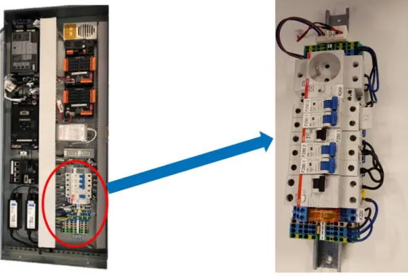
Figure 9. The inside of controller box (left) alongside the magnified view of switch module (right). [20]... 16
Figure 10. The factory floor layout for controller box assembly. [20] ... 17
Figure 11. The top view of switch module assembly. [21] ... 18
Figure 12. Simulated human robot collaborative assembly process. [20] ... 21
Figure 13. Shows the simulated collaborative workstation. ... 24
Figure 14. The top view of the collaborative workstation layout. Area enclosed in red boundary indicates the overlap region of human worker and COBOT’s workspace (also known as collaborative workspace). Area enclosed in green marks the human worker’s workspace. Area enclosed by blue is robot’s workspace. NOTE: All the dimensions are in millimeters. ... 25
Figure 15. Shows the High-level architecture of the system. ... 26
Figure 16. Manipulator joints and their axis specific jogging. [2] ... 27
Figure 17. Generic model of an impedance controller. Adapted from [23] ... 29
Figure 18. Implementation of compliant behavior with Cartesian Impedance Control Mode... 30
Figure 19. Non-configurable KUKA safety Configuration. ... 34
Figure 20. Configurable KUKA customer safety configuration. ... 35
Figure 21. The assembly stage decomposition model. Based on [16]. Note: Black arrows represent the direct connection between parts. Whereas, red arrows point (originate from the items outlined in red) towards the next assembly item in the sequence. ... 36
Figure 22. The commissioned collaborative workstation. ... 42
LIST OF SYMBOLS AND ABBREVIATIONS
OS Operating System.
CEN Comité Européen de Normalisation, European Committee for Stand-ardization.
CENELEC Comité Européen de Normalisation Électrotechnique, European Committee for Electrotechnical Standardization.
ETSI European Telecommunications Standards Institute. SME Small and medium-sized enterprises
R&D Research and Development.
ISO International Organization for Standardization.
ISO/TS International Organization for Standardization / Technical Specifica-tion.
TM Total operation time.
CM Total operation cost.
NM Total of theoretical minimum part count.
ICT Information and Communication Technology Systems. IIoT Industrial Internet of Things Products.
DFA Design for Assembly.
SCARA Selective Compliance Assembly Robot Arm or Selective Compli-ance Articulated Robot Arm.
HRC Human Robot Collaboration.
EU European Union.
CE-marking Conformité Européenne, European Conformity: CE - marking signi-fies that the product meets safety, health and environmental protec-tion requirements laid out for European economic area by the Euro-pean commission.
S/No. Serial Number
N/A Not Applicable.
TCP Tool center point.
COBOT A robot designed for direct interaction with a human within a defined collaborative workspace. [1]
AMF Atomic Monitoring Function. [2]
min Minutes.
s Seconds.
mm Millimeters.
N Newton - Unit of force.
1. INTRODUCTION
1.1 Background
Human Robot Collaboration, a concept not alien to the industry of our time but develop-ing at a dynamic rate; owdevelop-ing to the paradigms of the production processes. The idea nur-tures as the physical entities like robots, machines etc. become sophisticated due to the fusion of sensors, actuators, ICT systems etc. The goal being to integrate these intelligent entities with the human workforce so that they complement each other in the production processes; yet keeping it ergonomic. This is just a glimpse of the future of automation which aims to integrate the technology with the humans and their society. It is termed as the 4th Industrial revolution or Industry 4.0 [3].
1.2 The Problem Statement and Objectives
The purpose of this thesis is to analyze the human robot collaboration in assembly pro-cesses alongside the key technologies used in it.
1.2.1 Research questions and objectives
The research questions and objectives are listed below:
1. What DFA methodology axioms are relevant for designing applications involving human robot collaboration?
2. What are the rules for task allocation between humans and the robot? 3. What are the risks in human robot collaborative assembly process? 4. Is the human robot collaborative process reliable?
1.2.2 Limitations
To aid industrial deployment, open source and typical R&D software such as Robot op-erating system, and MATLAB etc. weren’t utilized. These softwares require intensive trainings regarding the knowledge areas of software engineering e.g. MATLAB script programming language, and Ubuntu OS etc. Industrial stakeholders are potentially ex-posed to heavy incurred costs as a result of these training activities. Apart from this, the open source software also need extensive testing for stability and security issues. The SMEs which serve as the backbone of the European economy [4] are reluctant to the use of such softwares. Therefore, commercial software which are commonly used in the local industry were utilized only. These are given as followed:
1. Use of Visual Components Software for layout planning and simulation. 2. Use of KUKA Sunrise.OS.
During the development of this thesis, external sensor systems (machine vision-based safety and quality checking systems) were not utilized. Alternatively, the following IIoT products were used:
1. Inherent input/output devices of the collaborative robot and its mobile base. 2. Industrial electric screwdriver with programmable controller.
This enabled the laboratory setup at Tampere University of Technology to correspond with the presented scenario of the case study.
1.2.3 Research and Development Process
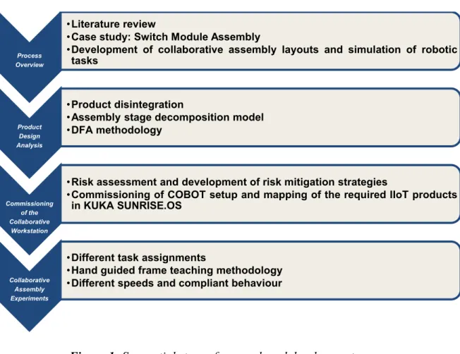
The research process, given in Figure 1, was used during the development of this thesis. It is divided into 4 steps. It starts with process overview. Switch module’s assembly
sim-ulations and technical documents were utilized to prepare the case study. Then different DIN rail assemblies were analyzed using Visual Components - 3D simulation software.
Figure 1. Sequential steps of research and development process
The product design analysis stage involves disintegration of the product. Assembly stage decomposition model was prepared for the product under investigation. It was also ana-lyzed using Design for Assembly (DFA) methodology tools and axioms.
Process Overview
•Literature review
•Case study: Switch Module Assembly
•Development of collaborative assembly layouts and simulation of robotic
tasks
Product Design Analysis
•Product disintegration
•Assembly stage decomposition model
•DFA methodology
Commissioning of the Collaborative
Workstation
•Risk assessment and development of risk mitigation strategies
•Commissioning of COBOT setup and mapping of the required IIoT products
in KUKA SUNRISE.OS
Collaborative Assembly Experiments
•Different task assignments
•Hand guided frame teaching methodology
During the third stage, risk assessment was carried out. At the latter parts of this stage, KUKA Sunrise project was readied and tested by installing it on the robot controller. The last stage involves testing of the collaborative assembly process for its reliability and productivity.
1.3 The Structure of the Thesis
This thesis is divided into 7 chapters. These are explained in the following text.
1. The first chapter introduces the reader to the problem statement of the thesis and its objectives.
2. The second chapter deals with the literature review. Industrial revolutions, human robot collaboration, safety requirements and product analysis methodologies are discussed in this chapter.
3. The third chapter presents the case study. This outlines the assembly requirements of the switch module i.e. the product under investigation.
4. The fourth chapter discusses the design and planning of the human robot collab-orative setup along with the necessary process details. This chapter includes: lay-out design, high level system architecture and risk/hazard assessment.
5. The fifth chapter discusses the design and implementation of the human robot collaborative assembly.
6. The sixth chapter gives the conclusions and results of this thesis.
7. The seventh chapter, which is the last one, discusses the future recommendations and developments.
2. LITERATURE REVIEW
The literature review presented here focuses on the related concepts and technologies which lead to the realization of human robot collaboration for the assembly of product under investigation.
2.1 Historical Context
–
Industrial Revolutions
The concept of human robot collaboration is evolving due to emergence of various latest technologies and knowledge areas like Internet of Things, Compliant robots etc. To delve deeper into the topic, industrial revolutions and their technological impacts were, hence, explored first.
Figure 2. The timeline of Industrial revolutions. Adapted from [5].
Figure 2 represents the key technologies that enabled the development of the industry alongside their outcomes in a chronological order. The First Industrial Revolution trans-formed the agrarian and handicraft producing societies into mechanized societies. Inven-tions such as steam engine along with other mechanical tools were essential in the devel-opment of the iron and textile industry. During the 19th century, the industries expanded
and grew due to innovation and advancement in technologies like electricity, internal combustion engine etc. Assembly lines led to mass production; thus, revolutionizing the industry and the environment.
The 20th century is considered the age of computers due to the development of digital
systems. Innovations in solid state electronics/physics enabled the production of intricate control systems. Thus, paving way for novel industrial solutions which varied from partial to fully automated processes; depending on production, societal, environmental etc. par-adigms.
The 21st century has seen the development of a lot of innovative technologies. These
technologies have emerged as market leaders and have also contributed towards a shifting trend in R&D. These include additive manufacturing, cloud computing, trainable systems, and complaint robots etc. to name a few. Such technologies have already started to usher environmental changes globally. However, the impact on the industry worldwide is more or less related to the empowerment of its workforce.
2.2 Human Robot Collaboration
Robots and IIoT devices are dominating the current world market. In the foreseeable fu-ture their influence is more likely to alter life at work and home. Practices related to work, health, environment, and safety etc. will transform with time to keep up with the increas-ing human robot interaction. Human robot interaction has paved new horizons in the mar-ket. Improvements have been seen in the delivered services alongside creation of new jobs and diversification of current value chains. For instance, since HRC is a novel area in the present market; therefore, technology transfer from R&D sector to the industry offers a lot of room and potential for value adding activities. Furthermore, manufacturing is a key value adding activity where usually the robots are deployed for large scale volume production. However, Europe, being the global leader in production and supply of indus-trial robotics, plans to deploy robots for small scale volume production. This is done to maintain and nurture Europe’s production base, which is vital for its wealth generation cycle. Usually, to keep the labor costs low, varied to full automation is carried out throughout the production processes. These solutions are productive if the setup and the running costs are low. But for the small-scale volume production, the automated solution must offer high flexibility alongside low incurred costs. To achieve this, many novel so-lutions have emerged in the market e.g. collaborative robots, trainable systems, and cus-tomized interactive user interfaces etc. These solutions enable the placement of robot alongside the human worker, during the manufacturing processes, without the need of having typical safety fences. This concept is termed as Human Robot Collaboration and it is explained in the following text. [6]
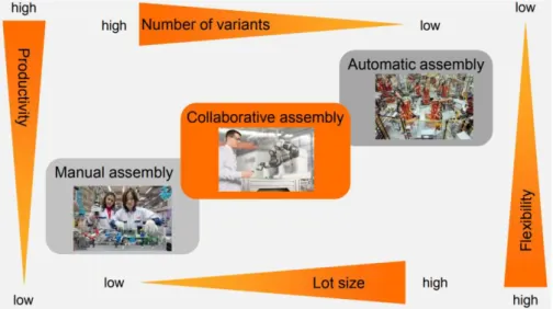
In human robot collaboration, the human and the robot work in partnership to complement each other for achieving a common production/manufacturing goal. It is achieved by providing specific set of capabilities. Usually, the robot assists the human worker in car-rying out non-ergonomic tasks e.g. repetitive tasks, lifting heavy objects etc. On the other hand, the human performs non-arduous tasks requiring human specific skills which are otherwise not feasible to be carried out by the robot e.g. human supervision, planning etc. However, human robot collaborative assembly lies midway, in comparison to manual and automatic assembly processes (Shown in Figure 3), when it comes to some key produc-tion metrics e.g. productivity, product variants, flexibility, and lot size etc. Automatic assembly is preferred when there is very less or almost no variation in products, high
productivity is required, and the commissioned setup remains unchanged unless it is re-quired for non-value-added tasks like maintenance etc. Manual Assembly process, on the contrary, is preferred when the lot sizes are low, productivity requirements are compara-tively low, product variants are high, and the assembly process requires it to be highly flexible. [7]
Figure 3.The comparison between manual, collaborative and automatic assembly. [7]
Figure 4 provides the idea of evolution of industrial robots and their respective work-spaces. In the first scenario the robot is confined to a fenced workspace and the human is absent from the workspace while the robot is carrying out the required task.
Figure 4. The concept of Human Robot Collaboration.
In the second scenario the robot is not fenced. However, the human is collaborating with
the robot while holding on to the dead man’s switch on the teach pendant to ensure safe
humans and its surrounding work environment. Moreover, a dead man’s switch ensures
safe robot operations and is activated if the operator is debilitated. In the third scenario, the robot utilizes its inherent sensors to ensure safety for the humans and its work envi-ronment. Therefore, the human collaborates with the robot confidently without having
the need to hold on to the dead man’s switch.
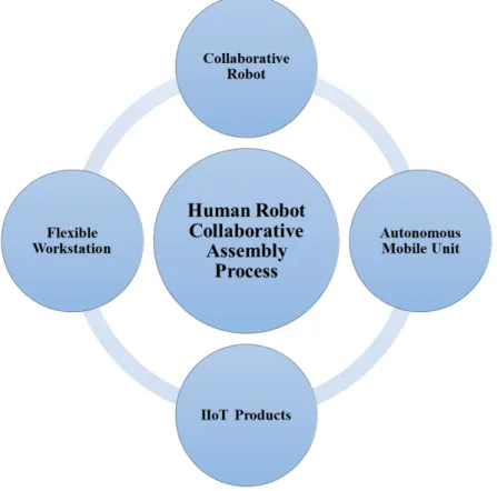
The research material presented here in the thesis focuses on full human robot collabora-tion and the key concepts involved in it are presented in Figure 5. A collaborative robot (COBOT) interacts directly with the human worker within the boundaries of a tive workspace to carry out manufacturing/production tasks simultaneously. A collabora-tive workspace is characterized by the autonomous operation of a robot. Safety for human workers is achieved in various ways e.g. varying speed on detection of human presence within the workspace [8], limiting the force delivered by a robot so that the separation between the robot and the human can be minimized etc. [9] [1]
Figure 5.The concepts/technologies used for the human robot collaboration in as-sembly processes.
The robot is mounted on an autonomous mobile unit which provides flexibility in the form of mobility and quick deployment. It houses all the important modules belonging to the robot and the Industrial Internet of Things (IIoT) devices. [10]
Flexible workstation provides ergonomic adjustments to the human robot collaborative process. Adjustable pick up shelves/feeders and assembly table height boost the assembly activities and ensure ergonomic conditions. IIoT Products such as robot operating system
(software), gripper system, external sensors, and actuators etc. exchange data via dedi-cated field buses. [5]
When the human and the robot are collaborating in a shared collaborative workspace, then the human can have two types of contacts with a robot. It can deliver static and dynamic forces to the human body. According to [11], these are of two types and given next:
1. Transient Contact 2. Quasi-Static Contact
Transient Contact is a type of contact between the human and the robot where the human body is not clamped in-between the robot’s structure and the workstation. It can retract and recoil after the contact. However, in case of Quasi-Static contact, the human worker’s
body part is clamped in between the moving/stationary part of the robot or its work cell. The human is unable to retract and recoil. These contacts pose significant risks to the robot and its environment. To mitigate these hazards different strategies could be adopted e.g. use of vision-based safety systems [8], and active compliance of the robot etc. How-ever, if the risk mitigation strategies are not applied carefully then it could result in an increase in the overall entropy of the process [12]. The same applies to the case of robot motion planning.
2.3 Safety and risk assessment requirements for Human Robot
Collaboration
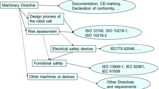
Figure 6. The overview of safety measures and requirements for Human Robot Col-laboration (HRC). [13]
A technical report presented by [13] gives an overview of the related standards and direc-tives for safe robot operations and these are schematically presented in Figure 6. Further explanation to the subject is given in the following text.
2.3.1 Machinery Directive
According to [14] a directive is defined as, “a legislative act that sets out a goal that all EU countries must achieve.” Therefore, it can be stated that the European Machinery Directive 2006/42/EC gives the necessary regulations regarding the health and safety re-quirements for a new machinery to be placed in the EU market. It ensures free movement of the machinery in the EU market. It also aims at providing maximum protection to EU residents and its industrial workforce. Key activities relating to the use of machinery di-rective are: risk assessment, preparation of technical manuals and instructions, CE-mark-ings at the machines, declaration of conformity documents (a declaration specifying the responsibility of design) etc. National laws (e.g. Finnish laws) regarding machinery, which are obligatory to follow, are defined according to the machinery directive.
This directive is further explained by the Harmonized Standards. These are developed on request of European commission by recognized European standards organizations such as: CEN, CENELEC, ETSI etc. The use of a harmonized standard is intentional, and it aims to give valid solutions within its scope.
Alongside harmonized standards, the machinery directive also refers to other standards and technical specifications such as ISO 12100, ISO/TS 15066 etc. to make machines and their operations safe.
2.3.2 Standards Type A-B-C
As per the definition of [15], Type-A standards are the basic safety standards which give basic concepts, principles for design and general aspects that are applicable to a machin-ery. Examples for this type are: ISO 12100 – Risk Assessment, IEC 61508 – Functional Safety, etc.
As per the definition of [15], Type-B standards give generic safety guidelines and these deal with one safety aspect or one type of safeguard which can be used across a wide range of machinery. Examples for this type are: ISO 13849 – Safety of machinery part 1 and 2, ISO 11161 – Integrated manufacturing systems etc.
As per the definition of [15], Type-C standards provide detailed safety guidelines for a particular machine or group of machines. These are also termed as individual safety stand-ards. Examples for this type are: ISO 10218-1 – Robot, ISO 10218-2 – Robot system/cell, ISO/TS 15066 – Collaborative Robots.
2.4 Assembly Stage Decomposition Model
To conduct thorough examination of the product and its assembly requirements different modeling techniques are used mostly. The product is disassembled before the creation of the model. This enables the identification of the various components and their assembly features. One such modelling technique was presented in [16] and its resulting schematic model is called Assembly Stage Decomposition Model (Shown in Figure 7).
Figure 7. Assembly stage decomposition model. [16]
It outlines the phases of the assembly alongside the added features/components of the product simultaneously. The case shown in Figure 7 represents the model for a mobile phone assembly, where the assembly process starts with the first phase. This involves securing the base part first to ensure a bottom up directional approach for assembly. A direct connection between the two components is shown by arrows and it represents func-tional and geometrical mating. However, an indirect connection between the two compo-nents is represented by a dot (between plastic layer and electric circuit during 3rd and 4th
phase of assembly). Indirect connection’s definition is based on precedence constraint scheduling logic. According to this logic several events/tasks are dependent on each other. And some tasks cannot be completed unless the other tasks on which it depends are car-ried out first. Moreover, the enclosed areas represented by A, B and C outline the subas-semblies of the product.
2.5 Design for Assembly (DFA) Methodology
Design for assembly is a concept which aims to facilitate the industrial workforce in de-signing/planning the assembly processes with maximum achievable production/manufac-turing metrics such as: efficiency, economy, ergonomics etc. However, in practice, usu-ally a compromise is made among these key metrics. [17] [18] [19]
2.5.1 Guidelines for DFA
DFA, simply put, aims to reduce the number of parts; thereby, simplifying the assembly process and reducing the timings involved in it. Moreover, DFA methodology could be better understood by the axioms identified from [17] and [18]. And these are given below:
1. Simplification of the joining methods. 2. Reduction of parts.
3. Minimizing the assembly directions.
4. Availability of options for modification/customization at the final assembly level. 5. Testable entities.
Decreasing the number of mechanical fasteners such as bolts, screws etc. in a product can ease the assembly process significantly by bringing down the part variability. Less num-ber of parts and reduced variation leads to simplification; thus, reducing potential mis-takes and unnecessary confusions. With this approach the assembly process design be-comes lean as the number of tool changes are reduced. Space issues which arise due to the use of tools in the assembly process, as they themselves consume a considerable amount of space on the assembly table/station and around the product, can be eliminated by simplifying the joining techniques. However, the joining methods should be designed in a way so that the product can be easily analyzed using qualitative and quantitative techniques. These analyses help the development of product and its life cycle.
Reduction of parts is a good strategy to simplify the assembly process. This approach saves the time in almost all the phases of production processes; such as: planning, execu-tion and monitoring/quality checks. The process of material handling and replenishment of the feeders becomes more simplified. As the individual parts have various costs asso-ciated with them, therefore, reduction of parts leads to an overall cost reduction of the final assembled product. A good design strategy is to combine the individual parts to-gether into chunks at every stage before the final assembly stage. Unless the reasons stated next are to be satisfied, a good practice would be to eliminate the part altogether or it should be integrated together with other similar parts. The reasons for part retention are:
1. The part moves with respect to other parts and these respective movements cannot be generated through the material properties or any other known methods. 2. Objectives related to the order of assembly and maintainability/service of the
3. If the intended design feature/function of the part is likely to be compromised because of integration; then it must be retained as an independent entity.
4. If the integration of part results in poor manufacturability (could be due to a lot reasons such as: production costs, complex molds etc.) then it should be retained as an independent entity.
Minimizing the direction types/changes for the assembly tasks is a general rule to keep the assembly process simple and lean. For industrial manipulators and SCARA robots, usually, a top-down approach is feasible. Moreover, the assembly process should be de-signed in a way so that the positioning of the part is well aided by the worker’s senses
e.g. visual perception, hearing, touch etc. Same goes for the automated assembly as well i.e. it should be well aided by the integrated sensors/IIoT products. For the manual as-sembly process, two hands should be enough for any asas-sembly task. However, if a task involves assembly by one hand then replacing the human workforce with an automated process (Preferably with an industrial manipulator/SCARA Robot) should be given a con-sideration.
Final assembly level customization capabilities provide the product life cycle profession-als with an opportunity to leverage their key process related resources: assembly automa-tion, quality testing, design economy, ergonomics etc. This strategy helps to eliminate the bottlenecks involved in an assembly process and aims to minimize the idle time associ-ated with work cells/stations.
The assembly process must be designed in a way so that the objective of providing lever-age for quality testing/troubleshooting endeavors can be achieved. For instance, in man-ual assembly tasks, the human worker should be able to assemble the product with qman-ual- qual-ity; and at the same time, he should be able to inspect it. Such an approach should be taken which allows the inspection of sub assembled parts at every stage of the assembly; thus, making the process as lean as possible. Modular design of the product and elimina-tion of loosely fit parts help in the realizaelimina-tion of this methodology.
2.5.2 DFA - Analysis
The purpose of DFA methodology and analysis (qualitative and quantitative) is to opti-mize the assembly process. The following methods have been used and mentioned in [17] and [18] for DFA analysis:
1. Qualitative and quantitative analysis of the assembly process steps. 2. Qualitative and quantitative analysis to identify part relevance. 3. Estimation of the cost of assembly
DFA analysis involves examination of parts, sub-assemblies and final assembly model/drawing/proposed sequences. Handling of parts, assembly orientations and non-value-added process steps are evaluated next. Then the parts are examined for similarities and relevance. The aim here is to determine the theoretical minimum number of parts to
reduce the actual part count and minimize the stages of assembly. These tasks are carried out in the future redesign processes. Evaluation and estimation of costs involved in the assembly processes are critical in the decision-making process of assembly task design. DFA analysis (work sheet sample shown in Table 1) involves some terminologies which are described next in this chapter:
1. Angle of symmetry (α+β) (Presented in Figure 8) 2. Operation time
3. Operation cost
4. Estimate of theoretical minimum part count 5. Design efficiency or DFA Index
Figure 8. The concept of total angle of part symmetry (α+β). [17]
The total angle of part symmetry (α+β) is evaluated in degrees and it ranges from 0 to 720 degrees. Alpha or α axis is the axis perpendicular to the direction of insertion. Alpha symmetry is the concept which depends on the angle (alpha angle) through which a part must be rotated about alpha axis. Whereas Beta or β axis is the axis in the direction of insertion. Beta symmetry is the concept which depends on the angle (Beta angle) through which a part must be rotated about the Beta axis. The design improvements related to this concept aim at reduction of the total angle of symmetry. [17]
The worksheet template for DFA analysis. [18] [17] C1 C2 C3 C4 C5 C6 C7 C8 C9 C10 NAME O F TH E P RO DUCT : P ART ID: T o tal An g le o f S ymm etr y ( α + β ), Degree s No . of t imes th e op e ratio n is ca rr ied o u t con se cut ive ly T w o -d igit Ma n u al Hand lin g cod e Ma n u al H and ling Tim e pe r part T w o -d igit man u al inse rt ion cod e Ma n u al in se rt ion t im e pe r part O p er atio n t ime, S e con d s ( 𝒕𝒎 ) O p er atio n cost , E u ro s ( 𝒄𝒎 ) E stim ate o f t h eore tic al mi n imu m p ar t cou n t Total DF A In de x = 𝑡 𝑚 ,𝑚 𝑖𝑛 × 𝑁𝑀 𝑇𝑀 = TM CM NM
The operation time (𝑡𝑚) combines all the timings related to an individual part. These usually involve the handling and insertion timings. Summation of the individual part op-eration times gives the total time of opop-eration referred to as TM in Table 1.
Similarly, operation cost (𝑐𝑚) combines all the costs associated with the individual part. The costs are usually evaluated depending on the material handling technique and the method of insertion utilized in the assembly task. Summation of the individual part oper-ation costs gives the total cost of operoper-ation referred to as CM in Table 1.
Theoretical minimum part count is the classification-based value evaluated from the anal-ysis of individual parts (of the final assembly). This analanal-ysis is based on the correspond-ence/symmetry in physical, functional etc. properties of the sub-assembly parts. It could also be based on the similarity of an operation e.g. similar fastening method, similar feed-ing method etc.
Design efficiency or DFA index is a percentage measure of how convenient it is to as-semble a product and it is given by:
𝐷𝐹𝐴𝐼𝑛𝑑𝑒𝑥 = 𝑡𝑚,𝑚𝑖𝑛 ×
𝑁𝑀
𝑇𝑀× 100% → (1)
Whereas, the variables used in this formula are described in Table 2.
Description of variables used in computation of DFA index. [17]
Variable Explanation
tm,min The basic assembly time (handling and insertion) of the part having minimum
value. It is taken as 3 s on average. TM Total operation time for the assembly in s. NM Total of theoretical minimum part count.
DFAIndex Also known as the design efficiency. Rule of thumb suggests this value to be
3. CASE STUDY: SWITCH MODULE ASSEMBLY
KONE Corporation, a world leader in the production of elevators and escalators, like all other industrial giants is exploring the field of full human robot collaboration. The human robot collaborative process was showcased as a 3D simulation in a seminar held in Espoo, Finland on March 07, 2018.
KONE elevator’s controller box (shown in Figure 9) assembly line was presented as a simulated scenario. Assembly of the switch module, which is an internal component of the controller box, was to be carried out by utilizing full human robot collaboration. [20]
Figure 9. The inside of controller box (left) alongside the magnified view of switch module (right). [20]
3.1 Factory Floor Layout
The current factory floor is shown in Figure 10. It only has human workers in the assem-bly, quality testing and packaging sections of the factory floor. Eight human workers are deployed on the assembly line to produce controller box for the elevators. Here they as-semble and inspect the product using naked eye while following the standard measures. Then the assembled product is forwarded to the quality testing area of the assembly floor.
Here 2 factory workers check the product for quality e.g. using multimeters etc. to ensure the circuits and the related modules are complete.
Figure 10. The factory floor layout for controller box assembly. [20] After the quality requirements are met, the controller box is forwarded to the packaging line via conveyer belts. A total of 5 human workers are deployed here for handling and packaging of the finished product. To see the potential of full human robot collaboration, the assembly of switch module was chosen to be the test product and it is discussed in the following text.
3.2 Product Description
The switch module consists of terminal blocks, circuit breakers, sockets and switches mounted on a DIN rail (Shown in Figure 11). It has electrical connections to two other modules of the controller box which are: control power module and lighting module [20]. The components along with their labels and quantity, according to their respective elec-trical drawings, are listed next in the Table 3.
Figure 11. The top view of switch module assembly. [21]
Later in the thesis, assembly cycle times shall be evaluated and discussed for the items given in Table 3. However, it should be noted that the components vary from one elevator model to another. The model shown in Figure 11 represents a particular case out of vari-ous models from different KONE factories around the globe.
The bill of materials for switch module assembly. [21]
S/No. Name of the item Labels Quantity
1 ABB E216 141: S 1 2 ABB Socket 274 1 3 ABB E251-230 K268 1 4 CHINT B10 F290:2 1 5 CHINT B6 F290:1 1 6 ABB D2 F286:3 1 7 CHINT D6 F286:2 1 8 CHINT C6 F286:1 1 9 ABB FH202 A F286 1
10 ZDU 2.5/4AN (GREY) 268L (CONTROL POWER MODULE), 286L (LIGHTING MODULE) 4 11 ZDU 2.5/4AN BL 290N (CONTROL POWER MODULE),
12 ZPE 2.5/4AN (GREEN) PE1 (CONTROL POWER MODULE), PE (LIGHTING MODULE) 4
13 DIN rail N/A 1
14 Wire Set
KM796121G12106, KM51042524G14,
KM51062820G10135 3
15 Labels N/A 21
3.3 Manual Assembly Process
Currently, according to [21], the assembly tasks are being carried out by the human work-ers. The quality control at this stage (assembly line) is carried out by visual inspection i.e. using naked eye. Moreover, there is one human worker per workstation for assembly task. The assembly steps are given below:
1. Clamping the DIN rail onto the assembly table.
2. One by one placing the components onto the DIN rail in the order given in Figure 9. The order of assembly could be either way from left to right and vice versa. 3. Making electrical connections by utilizing the provided set of wires and jumpers.
At this stage, designated screw drivers are used for securing the wires into the terminals.
4. Placing the respective labels on the DIN rail assembled components. 5. The switch module assembly is now complete.
This module can now be forwarded to the next work station or retained at the same work station for integration with other modules such as control power module, lighting module etc. The assembly cycle time for the switch module, shown in Figure 11, is around 11.5min. However, it only takes 3.5 - 4 min to complete the assembly of other individual modules (control power module, lighting module, etc.) of the controller box. Thus, it can be said that the sub assembly of the switch module is the bottleneck in the assembly pro-cess of controller box and has the highest cycle time of 11.5mins. [20]
Next the Takt time is evaluated according to different customer demands. Takt time de-termines the required speed with which an assembly task must be carried out to keep up with the customer demand. It is the ratio of total available production time to the average customer demand. [20]
Takt Time is given by:
𝑇𝑎𝑘𝑡 𝑇𝑖𝑚𝑒 =𝑇𝑜𝑡𝑎𝑙 𝐴𝑣𝑎𝑖𝑙𝑎𝑏𝑙𝑒 𝑃𝑟𝑜𝑑𝑢𝑐𝑡𝑖𝑜𝑛 𝑇𝑖𝑚𝑒
𝐴𝑣𝑒𝑟𝑎𝑔𝑒 𝐶𝑢𝑠𝑡𝑜𝑚𝑒𝑟 𝐷𝑒𝑚𝑎𝑛𝑑 → (2)
The available production time per day and three different customer demands, as presented in [20], are given next in Table 4:
Input values for the calculation of Takt times.
S/No. Variable Value Explanation
1 Total Available Production Time 7.5 Hours/Day Day Shift 2 DemandCustomer1 30 Units/Day Current Demand
3 DemandCustomer2 113 Units/Day Future Demand
4 DemandCustomer3 210 Units/Day Unusual Spike in
Demand
Therefore, the calculated Takt times are given next in Table 5:
Calculated Takt times for different customer demands.
S/No. Variable Value
1 Takt TimeCustomer1 15 min
2 Takt TimeCustomer2 3.98 or 4 min
3 Takt TimeCustomer3 2.14 min
The current setup with the available no. of resources is capable of coping with the current Takt time; since the highest cycle time is 11.5 min. However, to keep up with the future and unusual spikes in customer demands, more human workers are needed. The future demand for the human workers is discussed next.
For the future demand, having a calculated Takt time of 4mins, the highest cycle time is taken to be 3mins. To achieve this timing, 4 more assembly workers must be added to the existing assembly section and it is calculated next.
1 𝑎𝑠𝑠𝑒𝑚𝑏𝑙𝑦 𝑤𝑜𝑟𝑘𝑒𝑟 = 11.5 𝑚𝑖𝑛
𝑁𝑜. 𝑜𝑓 𝑎𝑠𝑠𝑒𝑚𝑙𝑏𝑦 𝑤𝑜𝑟𝑘𝑒𝑟𝑠 =11.5𝑚𝑖𝑛
3𝑚𝑖𝑛 = 3.83 𝑜𝑟 4
∴ 4 𝑎𝑠𝑠𝑒𝑚𝑏𝑙𝑦 𝑤𝑜𝑟𝑘𝑒𝑟𝑠 ≈ 𝑎 𝑐𝑦𝑐𝑙𝑒 𝑡𝑖𝑚𝑒 𝑜𝑓 3 𝑚𝑖𝑛 𝑓𝑜𝑟 𝑠𝑤𝑖𝑡𝑐ℎ 𝑚𝑜𝑑𝑢𝑙𝑒
Similarly, for the case of unexpected spike in demand, having a Takt time of 2.14 min, the cycle time was taken to be 1.83 min. This can be achieved by adding 7 workers to the existing assembly section of the factory floor. The calculations are given next:
1 𝑎𝑠𝑠𝑒𝑚𝑏𝑙𝑦 𝑤𝑜𝑟𝑘𝑒𝑟 = 11.5 𝑚𝑖𝑛
𝑁𝑜. 𝑜𝑓 𝑎𝑠𝑠𝑒𝑚𝑏𝑙𝑦 𝑤𝑜𝑟𝑘𝑒𝑟𝑠 =11.5𝑚𝑖𝑛
1.83𝑚𝑖𝑛= 6.28 𝑜𝑟 7
∴ 7 𝑎𝑠𝑠𝑒𝑚𝑏𝑙𝑦 𝑤𝑜𝑟𝑘𝑒𝑟𝑠 ≈ 𝑎 𝑐𝑦𝑐𝑙𝑒 𝑡𝑖𝑚𝑒 𝑜𝑓 1.83 𝑚𝑖𝑛 𝑓𝑜𝑟 𝑠𝑤𝑖𝑡𝑐ℎ 𝑚𝑜𝑑𝑢𝑙𝑒
Finally, it can be stated that 7 human workers are needed to cope with the highest men-tioned demand of 210 Units/Day. Moreover, a low Takt, and hence, a low cycle time suggests the assembly process to be non-ergonomic. The reason here is that the assembly task has become repetitive and spans over a very short time period; in comparison to the assembly process where the demand was merely 30 Units/Day. [20]
3.4 Human Robot Collaborative Assembly Process
For the customer demand of 113 Units/Day, the Takt time was calculated to be 4 min. And to achieve this, 4 more assembly workers need to be added to the assembly floor. Alternatively, the same result can be achieved by the addition of 2 human workers along-side 2 collaborative robots. Moreover, if there is an unusual spike in the customer demand i.e. 210 Units/Day then it could be managed by doubling the resources required to meet the demand of 113 Units/Day. This is calculated next:
113𝑈𝑛𝑖𝑡𝑠
𝐷𝑎𝑦 × 2 = 226
𝑈𝑛𝑖𝑡𝑠 𝐷𝑎𝑦
Therefore, as per the initial analysis, the collaborative setup has the potential of reaching 226 Units/Day. However, the main idea here is to shift the non-ergonomic tasks from the human worker to the COBOT. Additionally, the COBOT setup also offers flexibility in terms of operational deployment. For instance, the COBOT, when needed, can easily be shifted from the sheet cutting area of the factory to the assembly area of the factory; in order to assist the human worker in meeting the customer demand. In case of a temporary demand, it is considered rather convenient and quick to deploy a COBOT than to hire a new assembly worker for a short period of time. [20]
Figure 12. Simulated human robot collaborative assembly process. [20] Figure 12 shows the simulated scenario where the human worker performs the assembly task in collaboration with the collaborative robot. The task distribution among the human worker and the robot is given next in Table 6. During the execution of task no.1, the robot picks the DIN rail from the feeder and places it on the assembly table. The human worker secures the DIN rail with the help of a toggle clamp. After this, during the execution of
task no.2, the robot picks the electrical components from the feeders. During the execu-tion of task no.3, the robot assembles the components, picked up during the previous stage, on to the DIN rail. However, some components, which are inherently difficult to be grasped by the COBOT, are assembled by the human worker (These are numbered 10-12 in Table 3). Task no.4 is carried out by the human worker as it requires cognitive and precise grasping capabilities; which are inherently difficult to be provided by the current COBOT setup. To secure the electrical connections, the human worker houses the wire set into their respective terminals with one hand. Additionally, the human worker also guides the manipulator (COBOT), which holds the designated screwdriver, to the respec-tive screws on the components. Hence, it can be stated that task no.5 is done collabora-tively by human and the robot. The task no.6 (like task no. 4) requires precise grasping capabilities which cannot be provided by the current COBOT setup, therefore, the labels are placed by the human worker. [20]
Gives the assignment of assembly process tasks (for the simulated scenario) among the human worker and the robot. [20]
Table Key: ‘X’ sets the task assignment.
S/No. Task Human Robot
1 Securing the DIN rail on to the assembly table. X X
2 Picking up of DIN rail assembly components from the
feed-ers. X
3 Assembly of the components onto the DIN rail. X X
4 Guide and insert the wires into the respective components at correct positions X
5 Fastening the assembled components’ screws to secure
the electrical connections in the respective terminals. X X
6 Place labels on the assembled components X
The task assignments are based on some key factors which are: ability to grasp, repeata-bility, reliability and cognitive capability of the asset. However, some task assignments are done based on the feedback from the assembly workers. For instance, during the ex-ecution of task no. 5 (Presented in Table 6), manipulator’s gripper system holds the
des-ignated screwdriver (Usually industrial electric screwdriver). This is done to avoid the wrist injuries/sprains reported by the assembly workers. Such cases arise due to the re-petitive exposure of human wrist to the mechanical vibrations produced by the screw-driver during the assembly process. The robot during this stage is set in complaint mode
(discussed in detail in the later chapters of the thesis). This helps the operator in guiding and positioning of the screwdriver. The positioning is done in line with the specific screw (to be fastened) of the respective electrical component. Moreover, once the fastening op-eration starts, the unwanted vibrational energy generated by the screwdriver is effectively dissipated via virtual damper implemented as part of the complaint behavior of the ma-nipulator. [20]
Comparison of collaborative robot setups. [20]
S/No. Organization COBOT Reach Payload Autonomous
Mobile Unit Gripper
1 KONE Corp. KUKA LBR iiwa
14 R820 820mm 14kg KUKA flex-FELLOW H750 ex-tended Robotiq’s Adaptive 2 finger grip-per 2 TTY Founda-tion. KUKA LBR iiwa 7 R800 800mm 7kg KUKA flex-FELLOW H750 ex-tended SCHUNK EGP 50 Gripper (2 finger grip-per for small parts)
Table 7 gives the comparison between the COBOT setups. KONE Corporation’s setup
has more reach and can take more load. This enables it to be deployed elsewhere in the factory where it is needed. And it can effectively have more than one tool attached at the end of the robotic arm. Since both the setups are similar, and to promote Industry-Aca-demia collaboration, the simulated scenario along with the items given in Table 3 were provided to the ‘Mechanical Engineering and Industrial Systems Laboratory’ of Tampere
University of Technology (also referred to as TTY Foundation.). It was done to explore the simulated results in a practical environment. Additionally, it was encouraged to design the assembly process with the idea of human worker having gone through the operator’s training and having no skills in programming related knowledge areas. Therefore, the upcoming chapters discuss the design and commissioning of collaborative setup along with the productivity of the human robot collaborative assembly process.
4. SYSTEM DESIGN - COLLABORATIVE
OPERA-TION
4.1 Layout Design
The system design starts with the layout planning of the collaborative workstation. During the layout planning phase, a 3D simulation software is used (Visual Components for the case under study). The whole assembly process is simulated to analyze the robot’s reach,
poses and movements (while picking the components up from the rack and followed by assembly on the DIN rail). Components’ feeders are mounted on the rack (Labelled as 3 in Figure 13). There are two types of feeders in this collaborative setup and these are: gravity feeders and magazine type feeders.
The simulated scenario is shown in Figure 13. And the idea here is to have minimum possible idle time for the human worker and the robot. For instance, when the robot is picking and assembling the components from the feeders; the human prepares and then inserts the wires into the already fitted DIN rail components.
Figure 13 shows the collaborative workstation and this setup can be functionally divided into 3 parts. These are given next (as labelled in Figure 13 respectively):
1. Assembly table fitted with a toggle clamp to secure the DIN rail in a fixed posi-tion.
2. The COBOT setup – ‘KUKA LBR IIWA 7 R800’ mounted on ‘KUKA flexFEL-LOW H750 extended’.
3. Component inventory rack with feeders.
Figure 14. The top view of the collaborative workstation layout. Area enclosed in red boundary indicates the overlap region of human worker and COBOT’s
workspace (also known as collaborative workspace). Area enclosed in green marks the human worker’s workspace.
Area enclosed by blue is robot’s workspace. NOTE: All the dimensions are in millimeters.
Figure 14 is used to identify robot’s operational space and collaborative workspace.
Col-laborative workspace, as defined in [11], is the shared region between the human worker and the robot. During the assembly process, the human and the COBOT work simultane-ously in cooperation within this workspace. To detect the presence of human in the col-laborative workspace, COBOT’s inherent position and joint torque sensors were consid-ered in this design. No external sensors (e.g. laser scanners, cameras etc.) were considconsid-ered while designing the layout plan.
4.2 High Level Architecture
–
IIoT Products
KUKA Sunrise Cabinet (Robot Controller) runs KUKA Sunrise.OS 1.11. Offline Robot Programme is built on Sunrise.Workbench 1.11 which utilizes the Java programming lan-guage. The Sunrise.Workbench 1.11 on the Windows PC and the KUKA Sunrise.OS 1.11 synchronize the projects via Ethernet interface. A Java software project can also be in-stalled (usually the workbench and controller projects are synchronized) on the controller by clearing the previous projects or by overwriting them.
Figure 15. Shows the High-level architecture of the system.
The KUKA Sunrise Cabinet (Shown in Figure 15) has 3 field buses to ensure communi-cation between the robot controller and the IIoT products. Each of them is explained next:
1. KUKA Controller Bus (KCB) connects the Control PC (KPC) to the power drive system of the manipulator and KUKA flexFELLOW. Control PC (KPC) runs the KUKA Sunrise.OS 1.11.
2. KUKA System BUS (SYS-X48) is used for communication with the gripper sys-tem via Media Flange touch pneumatic.
3. KUKA Extension Bus (SYS-X44) is used to select the programs from the control-ler of the screwdriver via EK1100 EtherCAT-Koppler. EK1100 connects the EtherCAT with the EtherCAT Terminals (ELXXXX) e.g. EL2624 relay module is used to send input signals to the screwdriver’s controller.
4.3 COBOT Setup
The COBOT Setup comprises of KUKA LBR iiwa 7 R800 (Collaborative manipulator) mounted on KUKA flexFELLOW H750 Extended (Autonomous mobile unit). The mobile
unit acts as a base for the manipulator and houses the control/accessory units of the at-tached IIoT products. The manipulator is a 7 degrees of freedom robot (Shown in Figure 16).
Figure 16. Manipulator joints and their axis specific jogging. [2] The Offline Robot Programme, for the case under study, utilizes point to point (PTP) movements and linear (LIN) movements for the execution of assembly tasks. PTP move-ments are used for general orientation/positioning of the manipulator. However, linear movements are utilized where repeatability is required.
A point in space is presented by a frame in Offline Robot Programme. Frames are usually characterized by Task Space Coordinates (m) and redundancy information (presented in Table 8). Redundancy information, used for null space movements, is characterized by redundant coordinate angle ‘r’ (Value: 0 - 1 Radians) and joint configuration values; these are based on logical assignments which are presented in [22].
Configuration and task space coordinates. [2]
Coordinate System Value for KUKA LBR iiwa
Task Space Coordinates (m) m=6; 3D Cartesian Coordinates (x, y, z) and
Euler Angles (a, b, c)
Joint Space coordinates (n) n=7; seven joints – A1, A2, A3, A4, A5, A6,
A7.
During the execution of null space movements, the end effector’s position and orientation
is constant in space (m is constant in space). The idea behind null space movements is based on the fact that a point in the Cartesian space can be reached with multiple joint configurations (different set of joint values). Thus, the redundancy information is used to avoid unambiguous joint configurations during the planning and execution of different robot motions. During null space movements, the value of ‘r’ depends on the freedom of the 3rd joint. [22]
4.3.1 Sensors and available control modes
The KUKA iiwa LBR series manipulators, inherently, have two types of joint sensors and these are:
1. Joint position sensors 2. Joint torque sensors
In an ordinary industrial robot, joint position sensors are, generally, available only. How-ever, the controller implementations, are made possible due to the mentioned joint sen-sors. There are two types of controller implementations and these are:
1. Position controller
2. Cartesian impedance controller
Position controller makes sure that the current position always matches the set point on the commanded trajectory with minimal possible difference. Position controllers treat the external stimuli as disturbances and make sure that the set point is reached with minimum possible difference. Therefore, if there is any obstruction in the planned path then the robot tries to counter it by reacting towards it as a rigid structure. Apart from the damage
to the robot’s surrounding, excessive buildup of forces around or on the manipulator could ultimately damage it. Class PositionControlMode represents the position controller in Java Robot Offline Programme. If no control mode is specified in the Robot Offline Pro-gramme then this controller is utilized by default.
Figure 17. Generic model of an impedance controller. Adapted from [23] Cartesian impedance controller enables active compliance (complaint model discussed next in detail) for the robot. It is realized by acting on the information delivered by inher-ent sensors of the robot. The robot becomes sensitive to external stimuli like obstacles and forces. The whole kinematic chain becomes less rigid and more sensitive. External
forces in the robot’s path can cause it to deviate from its planned path. Cartesian imped-ance controller can be utilized through the class CartesianImpedimped-anceControlMode in Ro-bot Offline Programme. Figure 17 gives the concept of impedance controller. Whereas, the description of variables used in Figure 17 are given next:
𝒙𝒅∶ 𝑃𝑜𝑖𝑛𝑡 𝑎𝑙𝑜𝑛𝑔 𝑡ℎ𝑒 𝑐𝑜𝑚𝑚𝑎𝑛𝑑𝑒𝑑 𝑡𝑟𝑎𝑗𝑒𝑐𝑡𝑜𝑟𝑦 𝑖𝑛 𝑠𝑝𝑎𝑐𝑒.
𝒙 ∶ 𝐶𝑢𝑟𝑟𝑒𝑛𝑡 𝑝𝑜𝑠𝑖𝑡𝑖𝑜𝑛 (𝑇𝐶𝑃 𝑓𝑜𝑟 𝑜𝑢𝑟 𝑐𝑎𝑠𝑒) 𝝉𝒎𝒐𝒕𝒐𝒓 ∶ 𝑀𝑜𝑡𝑜𝑟 𝑡𝑜𝑟𝑞𝑢𝑒 𝑎𝑠 𝑜𝑢𝑡𝑝𝑢𝑡
According to [24], a compliant mechanism is defined as, “Mechanical systems which use their structural elastic deflection as a function.” In manipulators, active compliance is achieved by introducing a virtual spring-mass-damper system (Shown in Figure 18) in-between the end effector (TCP) of the manipulator and the commanded trajectory. The equation for the second order damped harmonic oscillator (spring-mass-damper system), as mentioned in [23], is given next:
𝑴𝒔∙ (𝒙𝒅̈ − 𝒙̈) + 𝑩𝒔∙ (𝒙𝒅̇ − 𝒙̇) + 𝑲𝒔∙ (𝒙𝒅− 𝒙) = 𝑭𝒆𝒙𝒕𝒆𝒓𝒏𝒂𝒍→ (3) Where, 𝑴𝒔 ∶ 𝑀𝑎𝑠𝑠 𝑚𝑎𝑡𝑟𝑖𝑥 𝑜𝑓 𝑡ℎ𝑒 𝑠𝑦𝑠𝑡𝑒𝑚. 𝑩𝒔 ∶ 𝐷𝑎𝑚𝑝𝑖𝑛𝑔 𝑀𝑎𝑡𝑟𝑖𝑥 𝑜𝑓 𝑡ℎ𝑒 𝑠𝑦𝑠𝑡𝑒𝑚. 𝑲𝒔 ∶ 𝑆𝑡𝑖𝑓𝑓𝑛𝑒𝑠𝑠 𝑀𝑎𝑡𝑟𝑖𝑥 𝑜𝑓 𝑡ℎ𝑒 𝑠𝑦𝑠𝑡𝑒𝑚. 𝑭𝒆𝒙𝒕𝒆𝒓𝒏𝒂𝒍∶ 𝑁𝑒𝑡 𝑒𝑥𝑡𝑒𝑟𝑛𝑎𝑙 𝑓𝑜𝑟𝑐𝑒 𝑚𝑎𝑡𝑟𝑖𝑥
The values of 𝑲𝒔and𝑩𝒔 can be assigned in the Robot Offline Programme. Whereas, the mass matrix is determined, inherently, by the KUKA Sunrise.OS 1.11’s robotic applica-tions package - ‘com.kuka.roboticsAPI’. It is based on end effector’s load information
Figure 18. Implementation of compliant behavior with Cartesian Impedance Control Mode.
4.4 Risk Assessment
In order to commission the collaborative workstation, risk assessment was performed to identify and mitigate hazards. For collaborative operations, the clauses 5.10.5, 5.11.5.5 and 5.5.5 of [9] (ISO 10218-1), [1] (ISO 10218-2) and [11] (ISO/TS 15066) respectively were considered. Moreover, the current system design was limited to the use of inherent sensors of the COBOT setup. Therefore, the identified risks could be mitigated by limit-ing the static and dynamic forces delivered by the manipulator to its surroundlimit-ing (human worker and the rest of the workstation). The inherent output devices of the COBOT setup could also be used to alert the assembly worker. Risk assessment was carried out, accord-ing to [25] (ISO12100), in the order given next:
1. Identification of the use cases. 2. Hazard identification.
3. Risk level estimation. 4. Risk mitigation.
Moreover, for detailed study the risk assessment worksheets, for the case under study, are
4.4.1 Identification of the use cases
The first step involves identification of the use cases, their respective actors and fre-quency. A total of 7 use cases were identified and these are given next:
1. Commissioning and robot offline programming 2. Assembly Operation – Automatic mode
3. Human Intervention in Robot only operating zone 4. Foreseeable malpractices in the assembly process 5. Maintenance/Service of collaborative workstation 6. Cleaning/Housekeeping
7. Decommissioning
The first use case involves commissioning of the robot and its offline programming. It is carried out by a certified robot commissioning engineer. This is done during the planning phase of the assembly process and the activity is carried out quite rarely; unless, a major change in the assembly process has to carried out. For instance, mapping of additional IIoT products (additional sensors or grippers) in the Robot Offline Programme.
The second use case involves the assembly operation. The robot’s operation mode is set
to Automatic mode (AUT) in this case. As this is a value adding activity, therefore, it is frequent and time consuming as compared to the other mentioned cases. Moreover, the human assembly worker and the robot have a constant and frequent interaction as well; since, they share the collaborative workspace (Area marked by red outline in Figure 14) during this phase.
The third use case involves human intervention in the robot only workspace (Area marked by blue outline in Figure 14). This case includes the human assembly worker; who has,
typically, gone through the operator’s training. However, the risky situation arises, if a feeding problem is detected. And the detected problem needs immediate correction in order to resume the normal assembly operation.
The fourth use case involves assembly process malpractices. This particular case focuses on the presence of a non-authorized personal within the premises of collaborative work-station. It could be anyone e.g. a visitor to the assembly area or a co-worker. The fre-quency of occurrence for this event is unknown prior to the commissioning of the collab-orative workstation. Since, the risk assessment is done, beforehand, during the planning stage.
The fifth use case involves the maintenance/service of the collaborative workstation. It is usually carried out by a trained technician/engineer. Maintenance/service activities are considered rare as these are usually carried out once a year.
The sixth use case involves housekeeping of the Collaborative workstation. It is carried out, on a daily basis by the human assembly worker, at the end of the work shift.
The last use case is about decommissioning of the collaborative workstation. It is carried out to ship the workstation. Or it could be done in order to dispose the workstation. It is considered to be a rare event as compared to the other mentioned use case activities.
4.4.2 Hazard identification
The second stage involves identification of hazards related to the previously mentioned use cases. 4 types of hazards were identified for the use cases and these are given next:
1. Entering Robot’s Workspace
2. Transient Contact 3. Quasi-Static Contact
4. Damage to the workstation (All 3 functional zones)
4.4.3 Risk level estimation
For the evaluation of risks involved in the already mentioned use cases, hazard rating number system was utilized. Table 9 gives the estimated risk levels.
It is observed that use case no. 2 and 4 have a higher risk level as compared to the rest of the use cases. During collaborative assembly the human assembly worker and the robot share the workspace all the time. They interact constantly during the whole assembly process. Therefore, the risk is considerable.
Moreover, for use case no.4, the risk is also considerable. The reason for this is based on the assumption that the non-authorized person (or persons) entering the collaborative workstation has not received any training or orientation for the collaborative work cell. Therefore, such an act could expose the work cell and its surrounding to unforeseeable hazards.
Risk level estimation results
S/No. Use Case Risk Level
1 Commissioning and robot offline programming Very Low Risk 2 Assembly Operation – Automatic mode Considerable Risk 3 Human Intervention in Robot only operating zone Very Low Risk 4 Foreseeable malpractices in assembly process Considerable Risk 5 Maintenance/Service of collaborative workstation Meaningless risk 6 Cleaning/Housekeeping Meaningless risk 7 Decommissioning Meaningless risk
![Figure 2. The timeline of Industrial revolutions. Adapted from [5].](https://thumb-us.123doks.com/thumbv2/123dok_us/1495761.2700276/11.892.167.807.472.718/figure-timeline-industrial-revolutions-adapted.webp)
![Figure 7. Assembly stage decomposition model. [16]](https://thumb-us.123doks.com/thumbv2/123dok_us/1495761.2700276/17.892.178.786.311.731/figure-assembly-stage-decomposition-model.webp)
![Figure 8. The concept of total angle of part symmetry (α+β). [17]](https://thumb-us.123doks.com/thumbv2/123dok_us/1495761.2700276/20.892.186.813.410.731/figure-concept-total-angle-symmetry-α-β.webp)
![Figure 10. The factory floor layout for controller box assembly. [20]](https://thumb-us.123doks.com/thumbv2/123dok_us/1495761.2700276/24.892.171.805.173.545/figure-factory-floor-layout-controller-box-assembly.webp)
![Figure 11. The top view of switch module assembly. [21]](https://thumb-us.123doks.com/thumbv2/123dok_us/1495761.2700276/25.892.230.740.109.610/figure-view-switch-module-assembly.webp)