S E L - 8 4 - 1 0 1
Manager's Handbook for
Software Development
Revision 1
NOVEMBER 1990
National Aeronautics and Space Administration
FOREWORD
The Software Engineering Laboratory (SEL) is an organization sponsored by the National Aeronautics and Space Administration/Goddard Space Flight Center (NASA/GSFC) and created for the purpose of investigating the effectiveness of software engineering technologies when applied to the development of applications software. The SEL was created in 1977 and has three primary organizational members: NASA/GSFC, Systems Development Branch; University of Maryland, Computer Sciences Department; Computer Sciences Corporation, Flight Dynamics Technology Group.
The goals of the SEL are (1) to understand the software development process in the GSFC
environment; (2) to measure the effect of various methodologies, tools, and models on this process; and (3) to identify and then to apply successful development practices. The activities, findings, and recommendations of the SEL are recorded in the Software Engineering Laboratory Series, a
continuing series of reports that includes this document.
The Manager's Handbook for Software Development was originally published in April 1984. Contributors to the original version included
William Agresti, Computer Sciences Corporation Frank McGarry, Goddard Space Flight Center David Card, Computer Sciences Corporation Jerry Page, Computer Sciences Corporation Victor Church, Computer Sciences Corporation Roger Werking, Goddard Space Flight Center
The new edition contains updated material and constitutes a major revision. The primary contributors to the current edition are
Linda Landis, Editor, Computer Sciences Corporation Frank McGarry, Goddard Space Flight Center Sharon Waligora, Computer Sciences Corporation Rose Pajerski, Goddard Space Flight Center Mike Stark, Goddard Space Flight Center Rush Kester, Computer Sciences Corporation Tim McDermott, Computer Sciences Corporation John Miller, Computer Sciences Corporation Single copies of this document can be obtained by writing to
Systems Development Branch Code 552
Goddard Space Flight Center Greenbelt, Maryland 20771
ABSTRACT
Methods and aids for the management of software development projects are presented. The recommendations are based on analyses and experiences of the Software Engineering Laboratory (SEL) with flight dynamics software development. The management aspects of the following subjects are described: organizing the project, producing a development plan, estimating costs, scheduling, staffing, preparing deliverable documents, using management tools, monitoring the project, conducting reviews, auditing, testing, and certifying.
TABLE OF CONTENTS
Section 1 — Introduction 1-1
Handbook Overview 1-1
Intended Audience 1-2
Software Life Cycle 1-3
Activities Spanning Phases 1-5
Section 2 — Organizing and Planning 2-1
Organizing the Project 2-1
Producing the Software Development/Management Plan 2-2
Executing the Software Development/Management Plan 2-5
Section 3 — Cost Estimating, Scheduling, and Staffing 3-1
Estimating Development Cost and Schedule 3-1
Project Staffing 3-4
Other Software Development Costs 3-5
Cost of Computer Utilization 3-5
Cost of System Documentation 3-7
Cost of Rehosting Software 3-7
Cost of Reusing Software 3-7
Cost of Software Maintenance 3-8
Section 4 — Key Documents and Deliverables 4-1
Suggested Document Contents 4-1
Guidelines for Evaluating Completed Documents 4-11
Section 5 — Verification, Testing, and Certification 5-1
Code Reading 5-1 Unit Testing 5-1 Integration Testing 5-2 Build/Release Testing 5-2 System Testing 5-3 Acceptance Testing 5-3
Test Management Guidelines 5-4
Certification 5-5
Section 6 — Metrics and Key Management Aids 6-1
Metrics 6-1
Management Metrics and Their Use 6-2
Source Code Growth Rate 6-3
Effort Data 6-4
TABLE OF CONTENTS (Cont'd)
Section 6 — Metrics and Key Management Aids (Cont'd)
Error Rates 6-8
Reported/Corrected Software Discrepancies 6-9
Rate of Software Change 6-10
Development Activity Status 6-11
Additional Management Metrics 6-12
Data Collection 6-13
Automating Metrics Analysis 6-13
General Indicators of Project Status 6-15
Warning Signals and Corrective Actions 6-16
Basic Set of Corrective Actions 6-18
Section 7 — Reviews and Audits 7-1
Reviews 7-1
System Requirements Review 7-2
Software Specifications Review 7-4
Preliminary Design Review 7-6
Critical Design Review 7-8
Operational Readiness Review 7-10
Audits 7-13
Appendix A — SEL Software Development Environment Glossary
References
LIST OF ILLUSTRATIONS
Figure Page
1-1 Activities by Percentage of Total Development Staff Effort 1-3 1-2 Reuse and Prototyping Activities Within the Life Cycle 1-5
2-1 Software Development/Management Plan Contents 2-3
3-1 Cost Estimation Schedule 3-2
3-2 Typical Computer Utilization Profile (FORTRAN Projects) 3-6
3-3 Typical Computer Utilization Profile (Ada Projects) 3-6
4-1 Key Documents and Deliverables by Phase 4-1
4-2 Requirements and Functional Specifications Contents 4-2
4-3 Operations Concept Document Contents 4-3
4-4 Requirements Analysis Report Contents 4-4
4-5 Preliminary Design Report Contents 4-5
4-6 Detailed Design Document Contents 4-6
4-7 Contents of Test Plans 4-7
4-8 User's Guide Contents 4-8
4-9 System Description Contents 4-9
4-10 Software Development History Contents 4-10
5-1 Example of Unit Design Certification 5-6
6-1 Management Through Measurement 6-2
6-2 SEL Software Growth Profile 6-3
6-3 Example of Code Growth — GRO AGSS 6-3
6-4 SEL Staffing Profile Model 6-4
6-5 SEL Effort Distribution Models 6-4
6-6 Effort Data Example — ERBS AGSS 6-5
6-7 SEL Size Estimates Model 6-6
6-8 Sample Size Estimates — UARS AGSS 6-6
6-9 SEL Computer Usage Model 6-7
6-10 Example of Computer Usage — ERBS AGSS 6-7
6-11 SEL Error Rate Model 6-8
6-12 Sample Error Rates — COBE AGSS 6-8
6-13 SEL Software Discrepancy Status Model 6-9
6-14 Example of Discrepancy Tracking — TCOPS 6-9
6-15 SEL Change Rate Model 6-10
6-16 Change Rate Example — GOES AGSS 6-10
6-17 SEL Development Status Model for a Single Build 6-11
6-18 Development Profile Example — GOADA 6-11
6-19 Example SME Output 6-14
6-20 Build Corporate Memory Into a Tool 6-15
7-1 Scheduling of Formal Reviews 7-1
7-2 SRR Hardcopy Material 7-3
7-3 SSR Hardcopy Material 7-5
7-4 PDR Hardcopy Material 7-7
LIST OF TABLES
Table Page
3-1 Distribution of Time Schedule and Effort Over Phases 3-1 3-2 Procedures for Reestimating Size, Cost, and Schedule
During Development 3-3
3-3 Complexity Guideline 3-3
3-4 Development Team Experience Guideline 3-4
3-5 Team Size Guideline 3-5
3-6 Guideline for Development Team Composition 3-5
3-7 Cost of Rehosting Software 3-7
3-8 Cost of Reusing Software 3-8
5-1 Expected Percentage of Tests Executed That Pass 5-5
SECTION 1 — INTRODUCTION
This handbook is intended to be a convenient reference on software management methods and aids. The approach is to offer concise information describing
• What the methods and aids can accomplish • When they can be applied
• How they are applied
• Where the manager can find more background or explanatory material The management methods and aids included here are those that have proved effective in the experiences of the Software Engineering Laboratory (SEL) (Reference 1). The characteristics of software projects in the flight dynamics environment monitored by the SEL appear in the appendix to this document. The applications include attitude determination and control, orbit adjustment, maneuver planning, and general mission analysis.
HANDBOOK OVERVIEW
This document consists of seven sections organized by specific management topics:
Section 1 presents the handbook's purpose, organization, and intended audience. The software life cycle and key development activities are summarized.
Section 2 discusses the basic management concerns of organizing and planning in the context of software management. The production of the software development management plan is covered in detail.
Section 3 describes resource estimation and allocation. Techniques are presented for estimating size, costs, and effort. Guidelines are given for project scheduling and for staff allocation and composition.
Section 4 outlines contents, timing, and evaluation of key documents and deliverables in a software project.
Section 5 discusses the management aspects of software verification, testing, and certification. Section 6 summarizes management measures and aids used in monitoring and controlling a
software project. Key indicators of progress are listed along with warning signals and corresponding corrective measures.
Section 7 presents both the general function of project reviews and the specific implementation of the five major reviews. Guidelines for auditing a project are also introduced.
An appendix, glossary, references, and a bibliography of SEL literature conclude the handbook.
INTENDED AUDIENCE
The intended audience of this document is the software manager, who, as defined in this handbook, serves as either an administrative or technical manager. The positions overlap somewhat in their information needs.
The administrative manager has overall responsibility for developing software that meets
requirements and is delivered on time and within budget. In the SEL environment, a Government Technical Officer or Assistant Technical Representative (ATR) generally serves in this capacity. Typically, this manager is not involved with the day-to-day technical supervision of the programmers and analysts who are developing the software. The administrative manager will be involved in the activities listed below; the corresponding handbook sections are listed alongside.
• Organizing the project Section 2
• Estimating resources required Section 3
• Estimating costs Section 3
• Evaluating documents and deliverables Section 4
• Monitoring progress Section 6
• Evaluating results of reviews and audits Section 7 • Certifying the final product Section 5
The technical manager is responsible for direct supervision of the developers. The position is frequently filled by a contractor manager in the SEL environment; although, on some projects, a Government manager will fill this role instead. This person shares some of the activities listed for the administrative manager, especially with regard to monitoring development progress. The technical manager's activities and the corresponding handbook references are presented below.
• Producing and executing the software
development/management plan Section 2
• Estimating costs Section 3
• Scheduling the project Section 3
• Staffing the project Section 3
• Directing the production of documents
and deliverables Section 4
• Using automated management aids Section 6 • Monitoring development progress Section 6
• Supervising technical staff Section 6
• Ensuring software quality Section 5
• Preparing for reviews Section 7
A secondary audience for the handbook consists of those who serve a particular peripheral function but do not act in either of the two managerial capacities. Two examples of such specific functions are participating as an external reviewer at a scheduled review and conducting an audit of the project. Government managers should note that there is no identifiable conflict between the material presented in this handbook and major NASA/GSFC standards.
SOFTWARE LIFE CYCLE
The process of software development is often modeled as a series of stages that define the software life cycle. In the flight dynamics environment, the life cycle is defined by the following phases:
• Requirements definition • Requirements analysis • Preliminary design • Detailed design • lmplementation • System testing • Acceptance testing
• Maintenance and operation
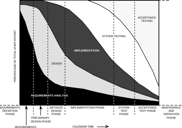
As shown in Figure 1-1, the phases divide the software life cycle into sequential time periods that do not overlap. However, the activities characteristic of one phase may be performed in other phases. For example, although most of the staff effort in analyzing requirements occurs during the
requirements analysis phase, some of that activity continues at lower levels in later phases.
PERCENTAGE OF TOTAL STAFF EFFORT
SYSTEM TEST PHASE IMPLEMENTATION PHASE REQUIREMENTS DEFINITION PHASE ORR SRR SSR PDR CDR CALENDAR TIME DESIGN IMPLEMENTATION SYSTEM TESTING ACCEPTANCE TESTING PRELIMINARY DESIGN PHASE REQUIREMENTS ANALYSIS PHASE ACCEPTANCE TEST PHASE MAINTENANCE AND OPERATION PHASE DETAILED DESIGN PHASE REQUIREMENTS ANALYSIS
Figure 1-1. Activities by Percentage of Total Development Staff Effort
E x a m p l e : At the end of the implementation phase (4th dashed line), approximately 46% of the
staff are involved in system testing; approximately 15% are preparing for acceptance testing; approximately 7% are addressing requirements changes or problems; approximately 12% are designing modifications; and approximately 20% are coding, code reading, unit testing, and integrating changes. Data are shown only for the phases of the software life cycle for which the
The life cycle phases are important reference points for the software manager. For example, in monitoring a project, the manager may find that the key indicators of project condition at one phase are not available at other phases. Milestones in the progress of a software project are keyed to the reviews, documents, and deliverables that mark the transitions between phases. Management aids and resource estimates can be applied only at certain phases because their use depends on the availability of specific information.
In the requirements definition phase, a working group of analysts and developers identifies previously developed subsystems that can be reused on the current project and submits a reuse proposal. Guided by this proposal , a requirements definition team prepares the requirements document and completes a draft of the functional specifications for the system. The conclusion of this phase is marked by the system requirements review (SRR) at which the requirements for the system are evaluated.
During the next phase, requirements analysis, the development team classifies each specification and performs functional or object-oriented analysis. Working with the requirements definition team, developers resolve ambiguities, discrepancies, and to-be-determined (TBD) specifications, producing a final version of the functional specifications document and a requirements analysis report. This phase is concluded with a software specifications review (SSR) at which the results of the analysis are presented for evaluation.
The baselined functional specifications form a contract between the requirements definition team and the software development team and are the starting point for preliminary design. During this third phase, members of the development team produce a preliminary design report in which they define the software system architecture and specify the major subsystems, input/output (I/O) interfaces, and processing modes. The preliminary design review (PDR), conducted at the end of this phase, provides an opportunity for evaluating the design presented by the development team.
In the fourth phase, detailed design, the system architecture defined during the previous phase is elaborated in successively greater detail, to the level of subroutines. The development team fully describes user input, system output, I/O files, and intermodule interfaces. An implementation plan is produced, describing a series of builds and releases that culminate with the delivered software system. The corresponding documentation, including complete baseline diagrams, makes up the detailed
design document. At the critical design review (CDR), the detailed design is evaluated to determine if
the levels of detail and completeness are sufficient for coding to begin.
During the implementation (code, unit testing, and integration) phase, the development team codes the required modules using the detailed design document. The system grows as new modules are coded, tested, and integrated. The developers also revise and test reused modules and integrate them into the evolving system. Implementation is complete when all code is integrated and when
supporting documents (system test plan and draft user's guide) are written.
The sixth phase, system testing, involves the functional testing of the end-to-end system capabilities according to the system test plan. The development team validates the completely integrated system and produces a preliminary system description document. Successful completion of the tests required by the system test plan marks the end of this phase.
During the seventh phase, acceptance testing, an acceptance test team that is independent of the software development team examines the completed system to determine if the original requirements have been met. Acceptance testing is complete when all tests specified in the acceptance test plan
have been run successfully. Final versions of the user's guide and system description are published, and an operational readiness review (ORR) is conducted to evaluate the system's readiness to begin operational support.
The eighth and final phase, maintenance and operation, begins when acceptance testing ends. The system becomes the responsibility of the maintenance and operation group. The nature and extent of activity during this phase depends on the type of software developed. For some support software, the maintenance and operation phase may be very active due to the changing needs of the users.
ACTIVITIES SPANNING PHASES
In the flight dynamics environment, reuse and prototyping are key activities in several phases of the life cycle.
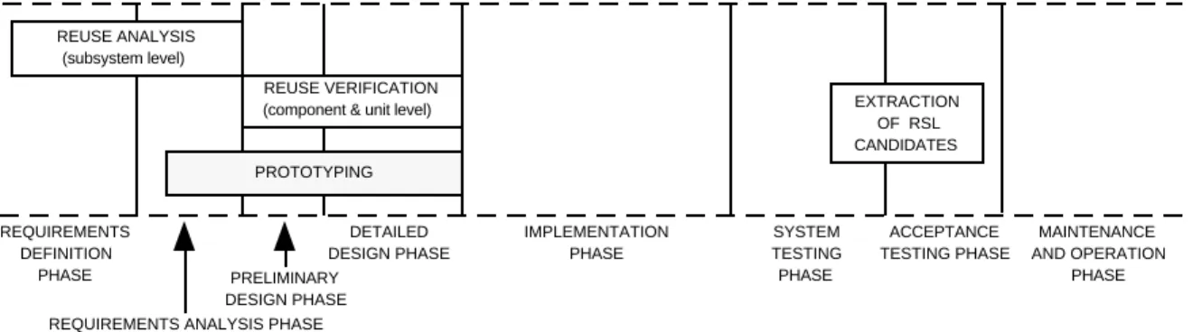
In the requirements definition and requirements analysis phases, reuse analysis is performed to determine which major segments (subsystems) of existing software can be utilized in the system to be developed. In the design phases, developers conduct a verification of this analysis by examining each reusable element individually. During the preliminary design phase, developers study major
components to determine if they can be reused verbatim or modified. Extraction of individual units
from a reusable software library (RSL) is conducted during the detailed design phase. A final reuse activity occurs at the end of the system test phase, at which time developers select pieces of the developed software as candidates for inclusion in the RSL.
Prototyping activities are usually begun during requirements analysis and completed by the end of detailed design. A protoype is an early experimental model of a system, system component, or system function that contains enough capabilities for it to be used to establish or refine requirements or to validate critical design concepts. In the flight dynamics environment, prototypes are generally used to mitigate risks by resolving unknowns related to new technology.
Figure 1-2 shows the span of these two categories of activity in the SEL environment.
REQUIREMENTS DEFINITION
PHASE
SRR SSR PDR CDR
REQUIREMENTS ANALYSIS PHASE PRELIMINARY DESIGN PHASE DETAILED DESIGN PHASE IMPLEMENTATION PHASE ACCEPTANCE TESTING PHASE SYSTEM TESTING PHASE ORR REUSE ANALYSIS (subsystem level) EXTRACTION OF RSL CANDIDATES PROTOTYPING MAINTENANCE AND OPERATION PHASE CALENDAR TIME REUSE VERIFICATION
(component & unit level)
Figure 1-2. Reuse and Prototyping Activities Within the Life Cycle The management methods and aids in this handbook are associated with the phases from requirements definition through acceptance testing. Reference 2 contains a more detailed explanation of life cycle phases and activities.
SECTION 2 — ORGANIZING AND PLANNING
The key to successful software management is to generate a realistic, usable plan and then follow it. The critical early stages of organizing and planning lay the foundation for effective project management and control.
ORGANIZING THE PROJECT
To get started, the manager must gain a clear understanding of the scope of the project and must establish the basis for control. The major initial concerns relate to clarifying the requirements, the deliverables, and the organizational framework. By addressing the four sets of questions below, the manager will acquire an understanding of the key elements that will affect project planning. Identifying the Requirements
What functions must the system perform? How will the system be operated?
Are the boundaries of the system visible? In what form does the job definition exist? Is the current job definition understandable?
Does the project depend on external events or activities?
Identifying the Products and Deliverables
What documents, programs, and files are specified as deliverable products? When must they be delivered?
In what form are the deliverables, e.g., draft copies or on tape? Who will receive the deliverables and accept the final product?
What criteria will be used to judge the acceptability of the final product?
Preparing for Control
Is there a timetable for periodic reporting of project status?
What is the procedure for incorporating requirements changes that affect the scope of the work?
What reviews will be necessary to mark the transitions between phases?
Are there technical or managerial risks to successful completion of the project? What measures will be used to assess project health?
Establishing an Organizational Identity
Who will be the key contact people from the customer, developer, and support groups? Do the different groups understand their areas of project responsibility?
Where will the development work be done? Which development computers will be used?
PRODUCING THE SOFTWARE DEVELOPMENT/MANAGEMENT PLAN
In many environments, the software management plan and the software development plan are separate policy documents with different orientations. The management plan is directed toward the broader aspects of administration and control, e.g., project-level monitoring of resource
expenditures and the functioning of the configuration control board (CCB). The development plan focuses more on methods and approaches to software production, e.g., testing strategies and programming methodologies. Although these differences exist between the two plans, there is generally some material in common.
ln the flight dynamics environment of the SEL, the two plans are combined into a single
document, the software development/management plan. Although the remainder of this section describes the contents of a single combined plan, the reader is encouraged to separate the contents into two plans if that is more appropriate to the needs of his/her environment. In either case, the items in this section must be formally addressed for a project to be successful.
The software development/management plan provides a disciplined approach to organizing and managing the software project. A successful plan serves as
• A structured checklist of important questions • Consistent documentation for project organization
• A baseline reference with which to compare actual project performance and experiences • A detailed clarification of the management approach to be used
By completing the plan early in the life cycle, the manager becomes familiar with the essential steps of organizing the development effort:
• Estimating resources • Establishing schedules • Assembling a staff • Setting milestones
The plan should concentrate on information that is unique or tailored to the project at hand. If standard policies, guidelines, or procedures will be applied to an aspect of the project, the plan should reference the documents in which these are defined rather than restating them in detail. Writing the plan can begin as soon as any information about the project definition and scope becomes available. The plan should be completed by the end of the requirements analysis phase, except for information available only at later phases. If items in the software development/ management plan are missing for any reason, the manager should indicate who will supply the information and when it will be supplied.
Copies of the plan should be provided to all levels of project management and the project's technical staff.
Figure 2-l presents the suggested format and contents for the software development/management plan, including several references to sections of this handbook for detailed descriptions. The format is intended as a guide. Depending on the application environment, a different arrangement of items or the addition of new material may be appropriate.
SOFTWARE DEVELOPMENT/MANAGEMENT PLAN
Sections in italics describe material that is to be regularly added to the plan during the life of the project. Other sections should be revised and reissued if circumstances require significant changes in approach.
TITLE PAGE — document number, project and task names, report title, and report date.
LEAD SHEET — document identification numbers, project and task names, report title, customer
name, preparers, contract and task identifiers, and report date.
TABLE OF CONTENTS — list of subsection titles and page numbers.
1. INTRODUCTION
1.1 Purpose — brief statement of the project's purpose.
1.2 Background — brief description that shows where the software products produced
by the project fit in the overall system.
1.3 Organization and Responsibilities
1.3.1 Project Personnel — explanation and diagram of how the development team
will organize activities and personnel to carry out the project: types and numbers of personnel assigned, reporting relationships, and team members' authorities and responsibilities (see Section 3 for guidelines on team composition).
1.3.2 Interfacing Groups — list of interfacing groups, points of contact, and group
responsibilities.
2. STATEMENT OF PROBLEM — brief elaboration of the key requirements, the steps to
be done, the steps (numbered) necessary to do it, and the relation (if any) to other projects.
3. TECHNICAL APPROACH
3.1 Reuse Strategy — description of the current plan for reusing software from
existing systems.
3.2 Assumptions and Constraints — that govern the manner in which the work
will be performed.
3.3 Anticipated and Unresolved Problems — that may affect the work and the
expected effect on each phase.
3.4 Development Environment — target development machine and programming
languages.
3.5 Activities, Tools, and Products — for each phase, a matrix showing: a) the
major activities to be performed, b) the development methodologies and tools to be applied, and c) the products of the phase (see Section 4). Includes discussion of any unique approaches or activities.
3.6 Build Strategy — what portions of the system will be implemented in which
builds and the rationale. Updated at the end of detailed design and after each build.
4. MANAGEMENT APPROACH
4.1 Assumptions and Constraints — that affect the management approach,
including project priorities.
4.2 Resource Requirements — tabular lists of estimated levels of resources
required, including estimates of system size (new and reused LOC and modules), staff effort (managerial, programmer, and support) by phase, training requirements, and computer resources (see Section 3). Includes estimation methods or rationale used. Updated estimates are added at the end of each phase.
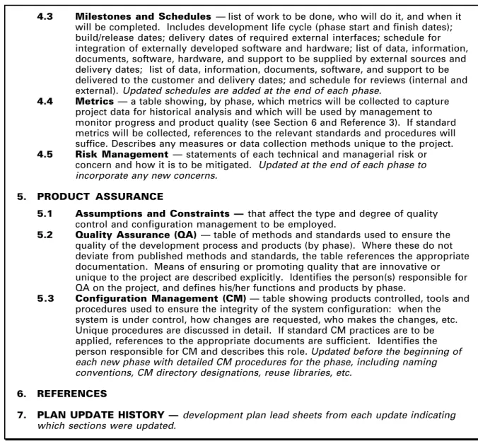
4.3 Milestones and Schedules — list of work to be done, who will do it, and when it will be completed. Includes development life cycle (phase start and finish dates); build/release dates; delivery dates of required external interfaces; schedule for integration of externally developed software and hardware; list of data, information, documents, software, hardware, and support to be supplied by external sources and delivery dates; list of data, information, documents, software, and support to be delivered to the customer and delivery dates; and schedule for reviews (internal and external). Updated schedules are added at the end of each phase.
4.4 Metrics — a table showing, by phase, which metrics will be collected to capture
project data for historical analysis and which will be used by management to monitor progress and product quality (see Section 6 and Reference 3). If standard metrics will be collected, references to the relevant standards and procedures will suffice. Describes any measures or data collection methods unique to the project.
4.5 Risk Management —statements of each technical and managerial risk or
concern and how it is to be mitigated. Updated at the end of each phase to incorporate any new concerns.
5. PRODUCT ASSURANCE
5.1 Assumptions and Constraints — that affect the type and degree of quality
control and configuration management to be employed.
5.2 Quality Assurance (QA) — table of methods and standards used to ensure the
quality of the development process and products (by phase). Where these do not deviate from published methods and standards, the table references the appropriate documentation. Means of ensuring or promoting quality that are innovative or unique to the project are described explicitly. Identifies the person(s) responsible for QA on the project, and defines his/her functions and products by phase.
5.3 Configuration Management (CM) — table showing products controlled, tools and
procedures used to ensure the integrity of the system configuration: when the system is under control, how changes are requested, who makes the changes, etc. Unique procedures are discussed in detail. If standard CM practices are to be applied, references to the appropriate documents are sufficient. Identifies the person responsible for CM and describes this role. Updated before the beginning of each new phase with detailed CM procedures for the phase, including naming conventions, CM directory designations, reuse libraries, etc.
6. REFERENCES
7. PLAN UPDATE HISTORY — development plan lead sheets from each update indicating
which sections were updated.
EXECUTING THE SOFTWARE DEVELOPMENT/MANAGEMENT PLAN
The plan will be an effective management aid only to the extent that it is followed. The manager must direct and control the execution of the plan by
• Maintaining it
• Measuring progress and performance • Recognizing danger signals . • Taking corrective action to solve problems
At the end of each development phase or build, the manager should reestimate project size, effort, and schedule for inclusion in the software development/management plan. Earlier estimates should not be removed from the plan. They provide a record of the planning process that will be needed for the software development history (Section 4). From this information, the organization can determine which estimation methods were effective and should be used again.
When it is effectively maintained, the development plan documents the current strategy for the software development effort. By providing a uniform characterization of the project, the plan can be invaluable if changes occur in team leadership.
Significant revisions to the plan should not be considered routine maintenance. Effort should be invested when the plan is written to ensure that it is realistic, rather than continually modifying it to agree with actual decisions or experiences. Major shifts in technical approach or use of
methodologies, for example, should occur only if necessary.
By measuring progress, the manager discovers whether the development/management plan is effective or not. Section 6 of this handbook addresses the types of metric data that should be collected and maintained as a record of project status.
Metric data alone are not sufficient for gauging the effectiveness of the plan, but by comparing these data to nominal values from related applications, some assessment is possible. Section 3 provides guidelines on resources and staffing that enable some comparison with the actual project data. The use of a project histories data base, as explained in Section 6, is another management aid for measuring progress.
SECTION 3 — COST ESTIMATING, SCHEDULING, AND
STAFFING
This section presents methods for managing and estimating the resources required for the software project. Two of the most critical resources are development staff and time. The software
manager is concerned with how much time will be required to complete the project and what staffing level will be necessary over the development cycle. Both staff and time are estimated using the procedures discussed in this section. Issues of staff size and composition over the life cycle are considered. Guidelines are provided for estimating some additional important cost elements such as computer utilization and system documentation. Reference 4 provides the background and rationale for software cost estimation.
A cautionary note applies to the cost factors throughout this section. The values summarized in the appendix to this document reflect SEL experiences in developing software for the flight dynamics environment. Readers of this handbook should assess how well that summary
matches their own software development environment as an indication of the degree of confidence to place in the particular cost values presented. A prudent plan is to use the values here as a first approximation and begin collecting data (see Reference 3) to obtain cost factors that are
representative of the reader's environment.
ESTIMATING DEVELOPMENT COST AND SCHEDULE
An understanding of the expected schedule consumption and effort expenditure in each phase of the life cycle is essential to managers. Figure l-l and Table 3-l present these distributions as they
reflect projects monitored by the SEL. Because the cost of developing software is often expressed in units of effort (e.g., staff-months) to avoid the effects of inflation and salary variation, cost and effort will be used interchangeably in this section when accounting for the expenditure of staff resources.
Table 3-1. Distribution of Time Schedule and Effort Over Phases
PHASE Requirements Analysis Preliminary Design Detailed Design Implementation System Testing Acceptance Testing 12 8 15 30 20 15 6 8 16 40 20 10 PERCENT OF TIME SCHEDULE PERCENT OF EFFORT
Although it is the most uncertain, the initial estimate is, in many ways, the most important. It occurs at such an early stage (after the requirements definition activity) that the temptation is strong to ignore it; to do so is a mistake. Making the initial estimate has the welcome side effect of leading the manager to consider the various factors bearing on the size and complexity of the development task. The initial estimate seeds the estimation process, serving as a reference value with which to compare later estimates. In view of this singular role, the following steps are suggested for achieving an initial estimate
• Decompose the requirements as far as possible. The decomposition unit at this point will probably be the subsystem.
• For each decomposition unit, identify similarities with functional units in previously developed systems and use any historical size data available from these completed systems.
• For decomposition units not strongly related to those of previous projects, use personal experience to estimate the size of units.
• Form the size estimate (in lines of code) for the entire project by adding the estimates for all the decomposition units.
• From historical data and personal experience, estimate the work rate (in lines of code per staff-month).
• Divide the size estimate by the work rate to obtain an estimate of the effort in staff-months. • Apply the uncertainty proportion of l.0 to the size and effort estimates to obtain a range of
possible values (See Figure 3-1 and Table 3-2).
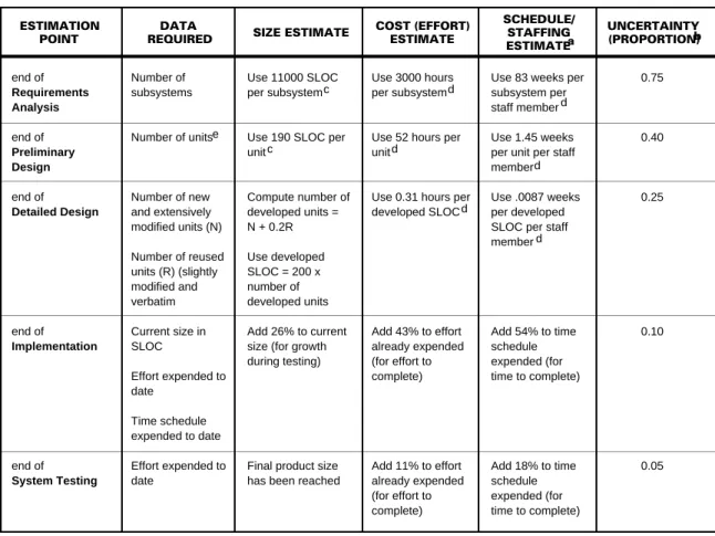
After the initial estimate is made, a minimum of five reestimates (numbered 2 through 6 in Figure3-l) are prescribed. These reestimates are detailed in Table 3-2. They are based on the increasing granularity in the representation of the system during the life cycle. The uncertainties from Figure 3-1 are repeated in Table 3-2 because of their importance in transforming the individual estimates into ranges of estimated values.
The estimation factors in Table 3-2 represent average values for typical development projects monitored by the SEL. The estimates should be adjusted (before the uncertainty proportion is applied) when the manager identifies certain aspects of the problem, process, or environment that vary significantly from customary development conditions. For example, when many modules within the system will be unusually large or small due to their specialized function (e.g., in generating graphics), their estimated size should be based on previously developed modules with similar
functions. In addition, any of the following conditions may strongly affect the effort necessary to complete the project: use of a new and dissimilar programming language, development by a completely inexperienced team, or the use of a new and dissimilar computer system.
The effects of some of these conditions have been estimated by the SEL. Table 3-3 provides the recommended percentage adjustment to the effort estimate due to the complexity of the problem. Table 3-4 provides an adjustment to the effort estimate for the effect of different team experience levels. LIFE CYCLE PHASES REQUIREMENTS DEFINITION AND SPECIFICATION REQUIREMENTS ANALYSIS DETAILED DESIGN IMPLEMENTATION SYSTEM TEST ACCEPT-ANCE TEST PRELIMINARY DESIGN 1 1.00 2 0.75 3 0.40 4 0.25 5 0.10 6 0.05 a ESTIMATES a
Reestimates should also be made at the end of each build or release of a staged implementation.
UNCERTAINTY (PROPORTION)
Table 3-2. Procedures for Reestimating Size, Cost, and Schedule During Development
ESTIMATION POINT
DATA
REQUIRED SIZE ESTIMATE
COST (EFFORT) ESTIMATE end of Requirements Analysis end of Preliminary Design end of Detailed Design end of Implementation end of System Testing Number of subsystems Number of units Number of new and extensively modified units (N) Number of reused units (R) (slightly modified and verbatim Current size in SLOC Effort expended to date Time schedule expended to date Effort expended to date Use 11000 SLOC per subsystem
Use 190 SLOC per unit Compute number of developed units = N + 0.2R Use developed SLOC = 200 x number of developed units Add 26% to current size (for growth during testing)
Final product size has been reached
Use 3000 hours per subsystem
Use 52 hours per unit
Use 0.31 hours per developed SLOC Add 43% to effort already expended (for effort to complete) Add 11% to effort already expended (for effort to complete) UNCERTAINTY (PROPORTION) b
Use 83 weeks per subsystem per staff member Use 1.45 weeks per unit per staff member Use .0087 weeks per developed SLOC per staff member Add 54% to time schedule expended (for time to complete) Add 18% to time schedule expended (for time to complete) 0.75 0.40 0.25 0.10 0.05 e c d
NOTE: Parameter values are derived from three attitude ground support systems (AGSSs): GOES, GRO, and COBE.
Schedule/staffing values are based on a full-time employee's average work week, with adjustments for holidays, leave, etc. (1864 hours annually). The values provided can be used to determine either schedule or staff level, depending on which parameter is given. Of size and effort estimates: Upper limit = (size or effort estimate) x (1.0 + uncertainty). Lower limit = (size or effort estimate)/ (1.0 + uncertainty). To allow for TBD requirements, staff turnover, etc., conservative management practice dictates the use of estimates that lie between the estimated value and the upper bound. SEL managers, for example, generally plan for a 40% increase in estimated system size from PDR to project end due to changing requirements.
Source line of code: a single line of executable or nonexecutable source code (including comments and embedded blank lines). Estimates of total effort (or time). Subtract effort (or time) already expended to get effort (or time) to complete.
Unit: a named software element that is independently compilable, e.g., a subroutine, subprogram, or function. a b c d e SCHEDULE/ STAFFING ESTIMATEa d c d d d d
Table 3-3. Complexity Guideline
Application, e.g., orbit determination, simulator. The project (or portion of the project) type is old when the organization has more than 2 years experience with it.
Computing environment, e.g., IBM 4341, VAX 8810. The environment type is old when the organization has more than 2 years of experience with it on average.
a b Old Old New New Old New Old New ENVIRONMENT TYPE b 1.0 1.4 1.4 2.3 EFFORT MULTIPLIER PROJECT TYPEa
Table 3-4. Development Team Experience Guideline
Average of team member's years of application experience weighted by member's participation on the team. Application experience is defined as prior work on similar applications, e.g., attitude and orbit determination. Member's participation is defined as time spent working on the project as a proportion of total project effort. a EFFORT MULTIPLIER 10 8 6 4 2 1 TEAM YEARS OF APPLICATION EXPERIENCEa 0.5 0.6 0.8 1.0 1.4 2.6
PROJECT STAFFING
Although the average level of staff is provided by the effort estimate, more specific guidelines are available for three aspects of staffing — team size, staffing pattern, and team
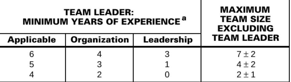
composition. Typical staffing profiles are provided in Section 6. Table 3-5 presents guidelines for team size in terms of the team leader's experience. Table 3-6 addresses team composition, listing recommended percentages of senior personnel and analysts.
Table 3-5. Team Size Guideline Applicable MAXIMUM TEAM SIZE EXCLUDING TEAM LEADER 6 5 4 3 1 0 4 3 2 7 ± 2 4 ± 2 2 ± 1 TEAM LEADER:
MINIMUM YEARS OF EXPERIENCE a Organization Leadership
Applicable Organization Leadership
= Applicable experience (requirements definition, analysis, development, maintenance, and operation).
= Experience with the organization and its development methodology. = Experience as a team leader or manager.
a
Examples: A team leader with no leadership experience should not be asked to manage a team with greater than three members. A team of seven to nine members should be provided with a leader who has six years or more of experience with the application, primarily within the organization.
Table 3-6. Guideline for Development Team Composition
PERCENTAGE OF ANALYSTSc 25-33 33-50 33-50 50-67 PERCENTAGE OF SENIOR PERSONNELb Old Old New New Old New Old New PROJECT TYPEa ENVIRONMENT TYPEa 25-33 25-33 33-50 33-50
The project and environment types are old when the development team has, on average, more than 2 years experience with them.
Senior personnel are those with more than 5 years of experience in development-related activities. Analysts are those personnel who have training and an educational background in problem definition and solution with the application (project type).
a b c
OTHER SOFTWARE DEVELOPMENT COSTS
Estimates and guidelines are presented for other software cost elements: computer utilization, system documentation, software rehosting, software reuse, and software maintenance.
Cost of Computer Utilization
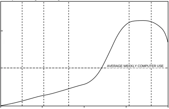
This cost may be expressed in terms of system size. The estimate of total hours of CPU time, H, in a NAS 8040 environment is H = 0.0008L, where L is the number of lines of source code in the system. (The NAS 8040 is comparable to an IBM 3033). The estimated number of runs, R, in the same SEL environment is R = 0.29L. Figures 3-2 and 3-3 show computer utilization over the life cycles of recent projects monitored by the SEL.
Requirements Analysis Preliminary Design Detailed Design Implementation System Test Acceptance Test
COMPUTER USE (PERCENT OF AVERAGE WEEKLY USE)
100% 200%
0 25 50 75 100
PERCENT OF DEVELOPMENT SCHEDULE
AVERAGE WEEKLY COMPUTER USE
Figure 3-2. Typical Computer Utilization Profile (FORTRAN Projects)
•
•
•
In comparison to FORTRAN, Ada projects utilize a larger percentage of CPU early in the life cycle
PDL and prolog are compiled during the design phases Integration testing is conducted throughout the implementation phase 100% Require-ments Analysis Pre-liminary Design Detailed Design Implementation System Test Acceptance Test 200%
COMPUTER USE (PERCENT OF AVERAGE WEEKLY USE)
0 25 50 75 100
PERCENT OF DEVELOPMENT SCHEDULE AVERAGE WEEKLY COMPUTER USE
Cost of System Documentation
Documentation cost is included in the cost estimates of Table 3-2. The average quantity of documentation for a given software development project can be estimated using the formula P = 120 + 0.026 L,where P is pages of documentation and L is source lines of code. This cost covers a requirements analysis report, design documents, system description, and user's guide. For a separate documentation task, 4 staff-hours per page may be used to estimate the total cost of system documentation.
Cost of Rehosting Software
Rehosting means modifying existing software to operate on a new computer system. Testing will require a high percentage of the total effort of any rehost project. Table 3-7 provides the cost of rehosting high-level language software as a percentage of the original development cost in staff-hours.
Table 3-7. Cost of Rehosting Software
Percent of original development cost. Percent of total rehosting cost.
Percent of code that must be newly developed or extensively modified.
Compatible: Systems designed to be plug compatible, (e.g., IBM S/360 and 4341).
Similar: Some key architectural characteristics, (e.g., word size) are shared and some are different (e.g., IBM 4341 and VAX 8810).
Data extracted from Reference 5.
Dissimilar: Differences in most characteristics of architecture and organization (e.g., IBM S/360 and PDP 11/70). a b c d e f g Compatible Similar Dissimilar 10-16 15-18 20-40 SYSTEM'S
RELATIONSHIP FORTRAN ADA
a RELATIVE COST 55-70 45-55 40-50 FORTRAN ADA b TESTING EFFORTS 5-11 10-15 18-30 36-40 30-35 25-30 0-3 4-14 15-32 d e CODEc NEW g f f f
Cost of Reusing Software
Reusable modules should be identified during the design stage. As shown in Table 3-8, the estimated cost to reuse a module depends on the extent of the changes.
Table 3-8. Cost of Reusing Software
Cost as a percent of the cost to develop a new module. a New Extensively Modified Slightly Modified Old MODULE CLASSIFICATION PERCENT OF MODULE'S CODE MODIFIED OR ADDED a RELATIVE COST 100 >25 1-25 0 100 100 20 20
Cost of Software Maintenance
Software maintenance refers to three types of activities occurring after the software is delivered — correcting defects detected during operational use, making enhancements that improve or increase functionality, and adapting the software to changes in the operational environment, such as a new operating system or compiler.
Expected maintenance costs vary widely, depending on the quality of the delivered software and the stability of the operational environment. In the environment monitored by the SEL, a large
percentage of the maintenance effort of FORTRAN systems is expended in enhancing the system. This includes modifying existing components, retesting, regenerating, and recertifying the software. Few new components are added, and new documentation is generally not produced.
Average annual maintenance effort ranges from 1 to 23% of the total development cost (in staff-hours) of the original system. Total maintenance over the life of the project costs from 1.5 to 24 staff-years per million LOC (see Reference 6).
Because maintenance effort varies so widely, the SEL recommends that estimates of the annual cost of maintenance be adjusted based on project type. The SEL uses 5% of total development cost as the estimate of annual maintenance of stable systems with a short life expectancy (less than 4
years). Annual maintenance of larger, longer lived systems is estimated at 15% of development cost.
SECTION 4—KEY DOCUMENTS AND DELIVERABLES
Documents and deliverables provide an ongoing system description and serve as key indicators of progress. They are a central concern of software managers because they mark the transitions between life cycle phases. The following documents and deliverables are of specific interest to the software manager:
• Requirements and functional specifications • Test plans
• Operations concept document • User's guide
• Software development/management plan • System description
• Requirements analysis report • Software development history
• Preliminary design report • System delivery tape — software
• Detailed design document product and supporting files and tools
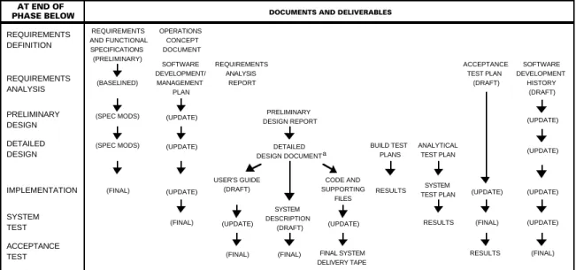
The documents and deliverables associated with a software development project are keyed to life cycle phases. Figure 4-l shows the phases when they should be completed. In some instances, preliminary versions are prepared, followed by updates. For any point in the life cycle, the software manager can determine what documents and deliverables should be in preparation. This section presents the recommended document contents as well as management guidelines for evaluating completed documents.
REQUIREMENTS ANALYSIS REPORT USER'S GUIDE (DRAFT) (UPDATE) (FINAL) REQUIREMENTS DEFINITION AT END OF
PHASE BELOW DOCUMENTS AND DELIVERABLES
SYSTEM TEST PLAN RESULTS BUILD TEST PLANS OPERATIONS CONCEPT DOCUMENT REQUIREMENTS AND FUNCTIONAL SPECIFICATIONS (PRELIMINARY) (BASELINED) (SPEC MODS) (SPEC MODS) (FINAL) PRELIMINARY DESIGN REPORT DETAILED DESIGN DOCUMENT SYSTEM DESCRIPTION (DRAFT) (FINAL) a CODE AND SUPPORTING FILES (UPDATE) FINAL SYSTEM DELIVERY TAPE RESULTS (FINAL) (UPDATE) ACCEPTANCE TEST REQUIREMENTS ANALYSIS PRELIMINARY DESIGN DETAILED DESIGN IMPLEMENTATION SYSTEM TEST
a The preliminary design report evolves into the detailed design document. Descriptive material in the detailed design document provides the basis for the system description. Updated prologs and program design language (PDL) from the detailed design are delivered with the final system and operations scenarios and performance information are included in the user's guide.
ANALYTICAL TEST PLAN ACCEPTANCE TEST PLAN (DRAFT) SOFTWARE DEVELOPMENT/ MANAGEMENT PLAN (UPDATE) (UPDATE) (UPDATE) (FINAL) SOFTWARE DEVELOPMENT HISTORY (DRAFT) (UPDATE) (UPDATE) (UPDATE) (UPDATE) (FINAL) RESULTS
Figure 4-1. Key Documents and Deliverables by Phase
SUGGESTED DOCUMENT CONTENTS
For each document, a suggested format and contents are given (see Figures 4-2 through 4-10), with the exception of the software development/management plan, which was covered separately in Section 2. The actual contents of the documents may vary from the outlines presented here. Specific features of the application environment may lead the manager to exercise judgment in selecting the material that is most appropriate and effective. This allowance for flexibility should be understood when examining the following figures.
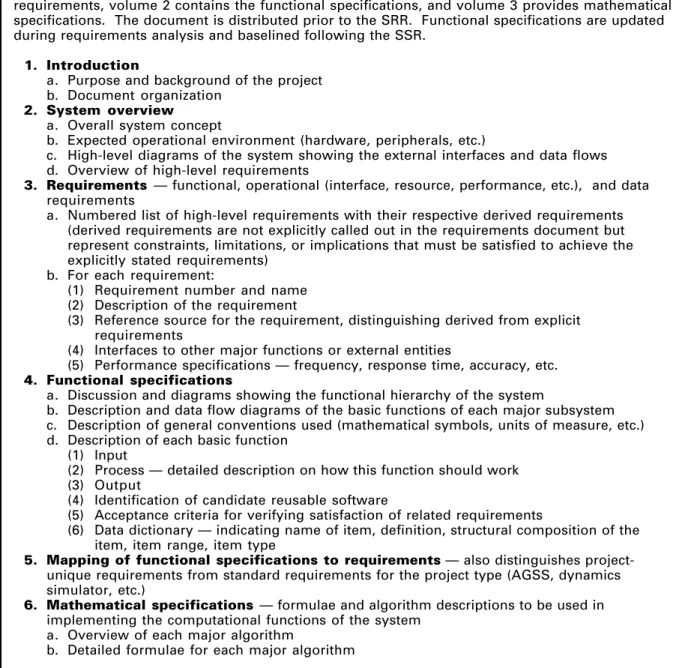
REQUIREMENTS AND FUNCTIONAL SPECIFICATIONS
This document is produced by the requirements definition team as the key product of the requirements definition phase. It is often published in multiple volumes: volume 1 defines the requirements, volume 2 contains the functional specifications, and volume 3 provides mathematical specifications. The document is distributed prior to the SRR. Functional specifications are updated during requirements analysis and baselined following the SSR.
1. Introduction
a. Purpose and background of the project b. Document organization
2. System overview
a. Overall system concept
b. Expected operational environment (hardware, peripherals, etc.)
c. High-level diagrams of the system showing the external interfaces and data flows d. Overview of high-level requirements
3. Requirements — functional, operational (interface, resource, performance, etc.), and data
requirements
a. Numbered list of high-level requirements with their respective derived requirements (derived requirements are not explicitly called out in the requirements document but represent constraints, Iimitations, or implications that must be satisfied to achieve the explicitly stated requirements)
b. For each requirement:
(1) Requirement number and name (2) Description of the requirement
(3) Reference source for the requirement, distinguishing derived from explicit requirements
(4) Interfaces to other major functions or external entities
(5) Performance specifications — frequency, response time, accuracy, etc.
4. Functional specifications
a. Discussion and diagrams showing the functional hierarchy of the system
b. Description and data flow diagrams of the basic functions of each major subsystem c. Description of general conventions used (mathematical symbols, units of measure, etc.) d. Description of each basic function
(1) Input
(2) Process — detailed description on how this function should work (3) Output
(4) Identification of candidate reusable software
(5) Acceptance criteria for verifying satisfaction of related requirements
(6) Data dictionary — indicating name of item, definition, structural composition of the item, item range, item type
5. Mapping of functional specifications to requirements — also distinguishes
project-unique requirements from standard requirements for the project type (AGSS, dynamics simulator, etc.)
6. Mathematical specifications — formulae and algorithm descriptions to be used in
implementing the computational functions of the system a. Overview of each major algorithm
b. Detailed formulae for each major algorithm
OPERATIONS CONCEPT DOCUMENT
This document provides a top-down view of the system from the user’s perspective by describing the behavior of the system in terms of operational methods and scenarios. It should be provided by analysts to the development team by the end of the requirements definition phase. The suggested contents are as follows:
1. Introduction, including purpose and background of the system
a. Overall system concept
b. System overview with high-level diagrams showing the external interfaces and data flow c. Discussion and diagrams showing the functional hierarchy of the system
d. Document organization
2. Operational environment, description and high-level diagrams of the environment in
which the system will be operated a. Overview of operating scenarios
b. Description and diagrams of the system configuration (hardware and software) c. Description of the responsibilities of the operations personnel
3. Operational modes
a. Discussion of the system's modes of operation (e.g., critical vs. normal, launch vs. on-orbit operations)
b. Volume and frequency of data to be processed in each mode
c. Order, frequency, and type (e.g., batch or interactive) of operations in each mode
4. Operational description of each major function or object in the system
a. Description and high-level diagrams of each major operational scenario showing all input, output, and critical control sequences
b. Description of the input data, including the format and limitations of the input. Sample screens (i.e., displays, menus, popup windows, etc.) depicting the state of the function before receiving the input data should also be included
c. Process — high-level description on how this function will work
d. Description of the output data, including the format and limitations of the output. Samples (i.e., displays, reports, screens, plots, etc) showing the results after processing the input should also be included
e. Description of status and prompt messages generated during processing, including guidelines for user responses to any critical messages
5. Requirements traceability matrix mapping each operational scenario to requirements
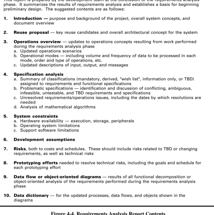
REQUIREMENTS ANALYSIS REPORT
This report is prepared by the development team at the conclusion of the requirements analysis phase. It summarizes the results of requirements analysis and establishes a basis for beginning preliminary design. The suggested contents are as follows:
1. Introduction — purpose and background of the project, overall system concepts, and
document overview
2. Reuse proposal — key reuse candidates and overall architectural concept for the system
3. Operations overview —updates to operations concepts resulting from work performed
during the requirements analysis phase a. Updated operations scenarios
b. Operational modes — including volume and frequency of data to be processed in each mode, order and type of operations, etc.
c. Updated descriptions of input, output, and messages
4. Specification analysis
a. Summary of classifications(mandatory, derived, "wish list", information only, or TBD) assigned to requirements and functional specifications
b. Problematic specifications — identification and discussion of conflicting, ambiguous, infeasible, untestable, and TBD requirements and specifications
c. Unresolved requirements/operations issues, including the dates by which resolutions are needed
d. Analysis of mathematical algorithms
5. System constraints
a. Hardware availability — execution, storage, peripherals b. Operating system limitations
c. Support software limitations
6. Development assumptions
7. Risks, both to costs and schedules. These should include risks related to TBD or changing
requirements, as well as technical risks
8. Prototyping efforts needed to resolve technical risks, including the goals and schedule for
each prototyping effort
9. Data flow or object-oriented diagrams — results of all functional decomposition or
object-oriented analysis of the requirements performed during the requirements analysis phase
10. Data dictionary —for the updated processes, data flows, and objects shown in the
diagrams
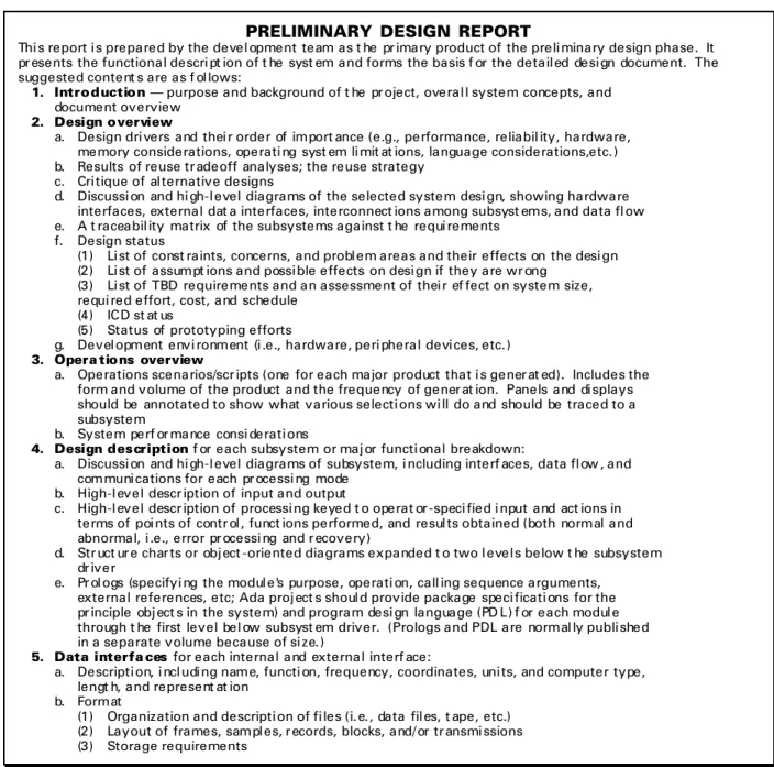
PRELIMINARY DESIGN REPORT
Thi s report i s prepared by the devel opment team as t he pr imary product of the preli minary design phase. It pr esents the functional descri pt ion of t he syst em and forms the basis f or the detail ed desi gn document. The suggested content s are as f ol lows:
1. Introduction — purpose and background of t he pr oject, overal l system concepts, and document overview
2. Design overview
a. Design dri vers and thei r order of import ance (e.g., performance, reliabil ity, hardware, memory considerations, operati ng syst em li mit at ions, language considerations,etc. ) b. Results of reuse tr adeoff analyses; the reuse strategy
c. Cri tique of al ternative designs
d. Discussi on and hi gh-I evel diagrams of the selected system desi gn, showing hardware interfaces, external dat a interfaces, interconnect ions among subsyst ems, and data fl ow e. A t raceabil ity matrix of the subsystems against t he requi rements
f. Design status
(1) Li st of const raints, concerns, and probl em areas and their effects on the desi gn (2) Li st of assumpt ions and possi ble effects on desi gn if they are wr ong
(3) Li st of TBD requirements and an assessment of thei r ef fect on system size, requi red effort, cost, and schedule
(4) ICD st at us
(5) Status of prototyping efforts
g. Devel opment envi ronment (i .e., hardware, peri pheral devi ces, etc. ) 3. Opera tions overview
a. Operations scenarios/scr ipts (one for each major product that i s gener at ed). Includes the form and volume of the product and the frequency of gener at ion. Panels and di splays should be annotated to show what various selecti ons wi ll do and should be traced to a subsystem
b. System perf or mance consi derati ons
4. Design description f or each subsystem or maj or functi onal breakdown:
a. Discussi on and hi gh-l evel diagrams of subsystem, i ncluding interf aces, data fl ow , and communi cations for each pr ocessi ng mode
b. High-I evel descr iption of input and output
c. High-l evel descr iption of processi ng keyed t o operat or -speci fied i nput and act ions in terms of poi nts of contr ol , funct ions performed, and resul ts obtained (both normal and abnormal, i .e., error pr ocessi ng and r ecovery)
d. Str uct ur e char ts or obj ect -oriented diagrams expanded t o two l evel s below t he subsystem dr iver
e. Pr ol ogs (specifyi ng the modul e's purpose, operati on, call ing sequence arguments, external references, etc; Ada proj ect s shoul d provide package speci ficati ons for the pr inciple obj ect s in the system) and program desi gn language (PD L) f or each modul e through t he first Ievel bel ow subsyst em driver. (Prologs and PDL are normal ly publi shed in a separate volume because of si ze. )
5. Data interfa ces for each internal and external interf ace:
a. Descripti on, i ncl udi ng name, functi on, frequency, coordinates, uni ts, and computer type, lengt h, and represent at ion
b. Format
(1) Organization and descripti on of fi les (i. e. , data fil es, t ape, etc.) (2) Layout of frames, sampl es, r ecords, blocks, and/ or tr ansmi ssions (3) Storage requirements
DETAILED DESIGN DOCUMENT
This document is the primary product of the detailed design phase. To complete the document, the development team updates similar material from the preliminary design report and adds greater detail. The suggested contents are as follows:
1. Introduction — purpose and background of the project, overall system concepts, and
document overview
2. Design overview
a. Design drivers and their order of importance b. Reuse strategy
c. Discussion and high-Ievel diagrams of the selected system design, showing hardware interfaces, external data interfaces, interconnections among subsystems, and data flow d. Traceability matrix of major components against requirements and functional specifications e. Design status
(1) List of constraints, concerns, and problem areas and their effects on the design (2) List of assumptions and possible effects on design if they are wrong
(3) List of TBD requirements and an assessment of their effect on system size, required effort, cost, and schedule
(4) ICD status
(5) Status of prototyping efforts f. Development environment
3. Operations overview
a. Operations scenarios/scripts
b. System performance considerations
4. Design description for each subsystem or major functional breakdown:
a. Overall subsystem capability
b. Assumptions about and restrictions to processing in each mode
c. Discussion and high-Ievel diagrams of subsystem, including interfaces, data flow, and communications for each processing mode
d. High-Ievel description of input and output
e. Detailed description of processing keyed to operator-specified input and actions in terms of points of control, functions performed, and results obtained (both normal and abnormal, i.e., error processing and recovery)
f. Structure charts or object-oriented diagrams expanded to the subprogram Ievel, showing interfaces, data flow, interactive control, interactive input and output, and hardcopy output
g. Internal storage requirements, i.e., description of arrays, their size, their data capacity in all processing modes, and implied Iimitations of processing
h. Detailed input and output specifications
(1) Processing control parameters, e.g., NAMELISTS
(2) Facsimiles of graphic displays for interactive graphic systems (3) Facsimiles of hardcopy output
i. List of numbered error messages with description of system's and user's actions j. Description of COMMON areas or other global data structures
k. Prologs or Ada package specifications and PDL for each unit (normally kept in a separate document because of size)
5. Data interfaces—updated from description in preliminary design report
TEST PLANS
BUILD/RELEASE TEST PLAN
• Prepared by the system test team during the detailed design phase
• Designed to test the functional capability of each build or release (functional subsets of the complete software system) as defined in the software development/management plan and to identify limitations
• Executed during the implementation phase by the system test team as soon as unit testing and integration of each build/release is complete
ANALYTICAL TEST PLAN
• Prepared prior to the implementation phase by the analysts who will use the system • Designed to assist developers in verifying the results of complex mathematical and
astronomical calculations performed by the system
• Unit level tests are executed during the implementation phase by developers; end-to-end tests are executed as a part of system testing
SYSTEM TEST PLAN
• Prepared by the system test team during the implementation phase
• Designed to verify the system's end-to-end processing capability, as specified in the requirements document, and to identify limitations
• Executed during the system testing phase by the system test team
ACCEPTANCE TEST PLAN
• Drafted by the acceptance test team following the requirements definition phase, based on the requirements and functional specifications document
• Designed to demonstrate the system's compliance with the requirements and functional specifications
• Executed during the acceptance testing phase by the acceptance test team
TEST PLAN OUTLINE
1. Introduction, including purpose, type and Ievel of testing, and schedule
2. Traceability matrix mapping each requirement and functional specification to one or more test cases
3. Test description (normally the Iength need not exceed 1 to 2 pages) for each test a. Purpose of test, i.e., specific capabilities or requirements tested
b. Detailed specification of input
c. Required environment, e.g., data sets required, computer hardware necessary d. Operational procedure, i.e., how to do the test
e. Detailed specification of output, i.e., the expected results
f. Criteria for determining whether or not the test results are acceptable
g. Section for discussion of results, i.e., for explaining deviations from expected results and identifying the cause of the deviation or for justifying the deviation
USER'S GUIDE
The development team begins preparation of the user's guide during the implementation phase. Items 1 and 2, and portions of item 3, represent updated material from the detailed design document, although some rewriting is expected to make it more accessible to the user. A draft is completed by the end of the implementation phase and is evaluated during system testing. At the beginning of the acceptance test phase, an updated version is supplied to the acceptance test team for evaluation. Corrections are incorporated, and a final revision is produced at the end of the phase. The suggested contents are as follows:
1. lntroduction
a. Overview of the system, including purpose and background b. Document organization
c. Discussion and high-level diagrams of system showing hardware interfaces, external data interfaces, software architecture, and data flow
2. Operations overview
a. Operations scenarios/scripts
b. Overview and hierarchy of displays, windows, menus, reports, etc. c. System performance considerations
3. Description for each subsystem or major functional capability:
a. Overall subsystem capability
b. Assumptions about and restrictions to processing in each mode
c. Discussion and high-Ievel diagrams of subsystems, including interfaces, data flow, and communications for each processing mode
d. High-level description of input and output
e. Detailed description of processing keyed to operator-specified input and actions in terms of points of control, functions performed, and results obtained (both normal and
abnormal, i.e., error processing and recovery)
f. For interactive subsystems, facsimiles of displays in the order in which they are generated g. Facsimiles of hardcopy output in the order in which it is produced, annotated to show
what parameters control it
h. List of numbered messages with explanation of system's and user's actions annotated to show the subroutines that issue the message
4. Requirements for execution
a. Resources — discussion, high-level diagrams, and tables for system and subsystems (1) Hardware
(2) Data definitions, i.e., data groupings and names
(3) Peripheral space considerations — data storage and printout
(4) Memory considerations — program storage, array storage, and data set buffers (5) Timing considerations
(a) Central processing unit (CPU) time in terms of samples and cycles processed
(b) I/O time in terms of data sets used and type of processing (c) Wall-clock time in terms of samples and cycles processed b. Run information — control statements for various processing modes
c. Control parameter information — by subsystem, detailed description of all control parameters (e.g., NAMELISTS), including name, computer type, length, and
representation, and description of parameter with valid values, default value, units, and relationship to other parameters