Heating and Cooling System
Upgrades
Course No: M03-022
Credit: 3 PDH
Elie Tawil, P.E., LEED AP
Continuing Education and Development, Inc.
22 Stonewall Court
Woodcliff Lake, NJ 07677
P: (877)
322-5800
EN E R G Y ST A R® Buildings Manual 1 HEATINGAND COOLING SYSTEM UPGRADES 11111
H
EATING
A
ND
C
OOLING
S
YSTEM
U
PGRADES
Overview
Heating and cooling systems are the largest single consumers of energy in buildings. These systems condition the air within a building so that occupants are comfortable. Heating and cooling systems consist mainly of chillers, boilers, cooling towers, and pumps. There are central heating and cooling systems, and unitary systems that combine heating and cooling. Opportunities exist for improvement to both central and unitary systems.
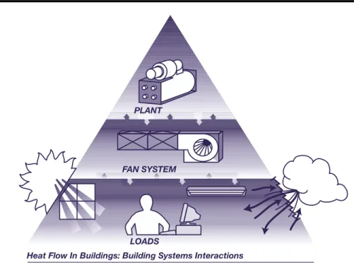
The heat flow diagram (Figure 1) illustrates how, you can capitalize on the heating, cooling, and electrical load reductions you have realized through your upgrades in the other stages of an integrated approach. The cumulative effect of these various load reductions now allows you to install heating and cooling systems that are both more energy efficient and properly sized to accommodate appropriate loads.
Heating and Cooling System Upgrades chapter will help you identify the opportunities for improving the performance of your heating and cooling system based on the type of system that you have in place. “Best Ways to Save” and “Take Action” provide checklists for cooling and heating upgrade opportunities and benefits. The Heating and Cooling Survey Appendix will assist you with evaluating the current condition of your systems and opportunities for improvement.
Heating and Cooling System Strategy • Measure your heating and cooling loads. • Rightsize your heating and cooling systems.
• Replace your chillers with new, more energy-efficient, non-chlorofluorocarbon (CFC) models.
• Upgrade your heating and cooling system components.
• Install variable-speed drives (VSDs) on your pumps and cooling tower fans. • Optimize operation of your heating and cooling systems.
EN E R G Y ST A R® Buildings Manual 2 HEATINGAND COOLING SYSTEM UPGRADES 22222
Figure 1: Heat Flow In Buildings
The Best Ways To Save
• Cooling System Upgrades – High Efficiency Components – Cooling Tower Improvements – Free Cooling
– VSD Pumping – Controls
• Heating System Upgrades – High Efficiency Components – Controls
Table 1: Potential Cooling and Heating Energy Savings System Typical Savings
Cooling Central Chiller 15–35% Unitary A/C 20–35% Heating Boiler 10–30% Furnace 5–25%
Adapted from: E SOURCE, Space Cooling Technology Atlas and E SOURCE, Space Heating Technology Atlas.
LOADS
Heat Flow In Buildings: Building Systems Interactions
Figure 2 shows the interaction of heating, cooling, and electrical loads with the HVAC equipment. Arrows indicate heat flow pathways. Reducing heating, cooling, and electrical loads reduces the demand on HVAC equipment, thus saving energy.
PLANT
EN E R G Y ST A R® Buildings Manual 3 HEATINGAND COOLING SYSTEM UPGRADES 33333
Use An Integrated System Approach
The conventional approach to upgrading a heating and cooling system is to address each component of the system individually. However, addressing the interaction between the components using an integrated system approach ultimately results in a more energy-efficient system. In addition, compared with assessing components individually, assessing upgrade opportunities for whole systems consumes less time, and therefore less money, in the long term. Heating and cooling system components, particularly in central systems, interact with each other extensively. For example, chillers operate more efficiently if they receive cooler condenser water. However, the cooling tower fans consume more energy to provide cooler condenser water.
Optimizing the energy use of the cooling tower/chiller system is one example of using an integrated system approach that can improve your energy performance and save money.
Heating and Cooling System Energy Use
Cooling may use as much as a third of the electricity consumed in a typical building. Heating systems use natural gas or oil as the primary fuel, but may also use electricity. Heating and cooling systems condition the air within a building so that occupants are comfortable. These systems consist mainly of chillers, boilers, cooling towers, and pumps. Cooling systems generally have higher space conditioning capacities than heating systems, because a large portion of the building’s heating requirements is supplied by waste heat from the people, lighting, and office equipment. The proper design and operation of these systems can translate into significant savings. If you have followed the steps outlined in the other stages, your cooling load may now be low enough to justify retrofitting or rightsizing your cooling system.
Advantages Of A Rightsized System
In addition to reducing energy consumption and costs, heating and cooling upgrades will:
• Reduce noise.
• Lower first costs for equipment. • Reduce equipment footprint. • Eliminate CFCs.
• Optimize equipment operation
Take Action!
1. Measure your existing heating and cooling loads. To begin, see the Heating and Cooling Survey (Appendix). Contact an engineering services firm for the more complex load measurement tasks.
EN E R G Y ST A R® Buildings Manual 4 HEATINGAND COOLING SYSTEM UPGRADES 44444
stages. Calculate the proper size for your chiller. See the Heating and Cooling Survey (Appendix).
3. Use the information from the Heating and Cooling Survey to investigate options for upgrading your chiller plant.
4. Contact vendors and/or an engineering consultant who can recommend specific components and design upgrades for your heating and cooling system.
Central Cooling Systems: Best Opportunities
Cooling systems consist of various components that must work together to operate at highest efficiency while ensuring proper occupant comfort. Improvements to any system must, of course, incorporate improvements to its individual pieces of equipment. However, these changes must be viewed as part of an integrated system approach. To improve your building’s overall efficiency, modifications in the design or operation of one set of components will affect, the operation of other equipment within the system.
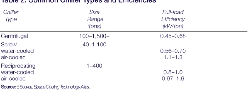
There are four types of mechanical compression chillers—centrifugal, screw, scroll, and reciprocating, different applications call for different chiller types. Generally, older chillers have efficiencies ranging from 0.8 to 1.0 kW/ton; they often consume
approximately twice the energy of newer, more efficient chillers. Today, centrifugal chillers have efficiencies as low as 0.45 kW/ton. Table 2 shows the efficiency ranges in which these chiller technologies.
Eliminating CFCs:
Headache Or Opportunity?
• CFC refrigerant production was phased out by law in 1996. As existing stock of CFCs dwindle and become more expensive, conversion to or replacement with non-CFC chillers is becoming more cost effective.
• Existing, relatively new chillers may be cost effective to retrofit for non-CFC operation. • Replacing an older chiller with a new, non-CFC chiller is an excellent opportunity to
in-vest in a high efficiency unit. First cost for the installation will be reduced by installing a smaller chiller made possible by the implementation of all upgrade stages.
Chiller Retrofit
If the existing chiller is less than 10 years old, retrofitting the chiller to operate on non-CFC refrigerants at the newly reduced loads will probably be your most profitable option. This postpones investing in a new chiller. When you are replacing refrigerant, use HCFC-123 in place of R-11 and HFC-134a in place of R-12. Retrofitting may involve replacing orifice plates, impellers, gaskets, or even the compressor. The specifics of the retrofit depend on the type of chiller and its manufacturer. Many manufacturers offer retrofit kits for their chillers. Contact the manufacturer of your chiller to determine its requirements.
EN E R G Y ST A R® Buildings Manual 5 HEATINGAND COOLING SYSTEM UPGRADES 55555
Due to their inherent properties, non-CFC refrigerants are not as efficient and thus will affect the chiller efficiency by reducing its cooling tonnage at current or even increased levels of energy consumption. However, the reduced cooling loads obtained through performing a comprehensive upgrade will offset this loss.
Table 2: Common Chiller Types and Efficiencies
Chiller Size Full-load Type Range Efficiency (tons) (kW/ton) Centrifugal 100–1,500+ 0.45–0.68 Screw 40–1,100 water-cooled 0.56–0.70 air-cooled 1.1–1.3 Reciprocating 1–400 water-cooled 0.8–1.0 air-cooled 0.97–1.6
Source: E SOURCE, Space Cooling Technology Atlas.
CFCs Are On The Way Out
Eighty percent of today’s existing chillers are centrifugal chillers that use R-11 as refrig-erant. The newer, non-CFC alternative to R-11 is HCFC-123. Some centrifugal chillers use R-12; its non-CFC alternative is HFC-134a. Unitary A/C units typically use R-22, which will be phased out in the future.
Phase-Out Dates Refrigerants Action
1996 R-11, R-12, Production of these refrigerants
R-500,HCFC-152A, has stopped. Equipment
CFC-114 using these refrigerants is no
longer manufactured.
2010 HCFC-22 Manufacture of equipment
using this refrigerant has stopped
2020 HCFC-123 Manufacture of equipment
using this refrigerant has stopped
2030 HCFC-22 Production of this refrigerant
has stopped.
2030 HCFC-123 Production of this refrigerant
has stopped.
Source: ASHRAE Fundamentals Handbook, 2001..
Chiller Rightsizing
Depending on the upgrades implemented in the previous stages, loads on your cooling system (see Figure 2) likely have been reduced by at least 10 percent, and perhaps by as much as 40 percent. Even if you haven’t implemented upgrades, design loads and actual building demand rarely match.
Chillers are frequently oversized, and those in poor condition suffer downtime and significantly increased operating and maintenance costs. A new efficient and reliable chiller may be more cost effective. Thus, you may want to consider rightsizing your
EN E R G Y ST A R® Buildings Manual 6 HEATINGAND COOLING SYSTEM UPGRADES 66666
existing chiller with a new, smaller, energy-efficient one that matches the newly reduced loads and uses compliant non-CFC refrigerants. This option is most profitable when your existing chiller is more than 10 years old.
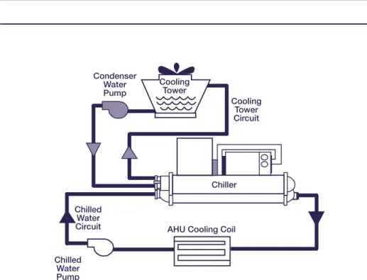
Figure 2: Typical Water-Cooled Chiller System
When you decide to replace an existing chiller with an energy efficient unit, be sure to evaluate the initial operating and maintenance costs, size, and weight of the new unit. Keep in mind that the energy consumption of a new high efficiency chiller could range from 15 percent to more than 50 percent less than that of the existing chiller.
While the new chiller must be sized for peak loads, be sure that it operates efficiently at part-load conditions, because it is at part load that the chiller operates most of the time. Many chiller manufacturers provide electronic copies of their equipment specifications catalogs on CD-ROM. This information can be used to identify the appropriate chiller for your facility, once you have analyzed the building’s peak load profile. An energy services professional or consulting engineer can develop the new peak load profile.
To analyze the profitability of chiller upgrades, you will need to identify the relationship between outdoor air temperature and the cooling load that the chillers must meet. Consult the chiller manufacturer’s specifications to prepare a load profile for your building gathered using the Heating and Cooling survey (Appendix).
Condenser Water Pump Cooling Tower Cooling Tower Circuit Chiller Chilled Water Circuit Chilled Water Pump
EN E R G Y ST A R® Buildings Manual 7 HEATINGAND COOLING SYSTEM UPGRADES 77777
To evaluate the chiller project, gather data about existing chillers, operating schedules, utility rate schedules, cooling tower parameters, and water reset temperatures for the condenser and evaporator.
Chiller Rightsizing Case Study: An ENERGY STAR Showcase Building
Mobil Corporation’s 340,000-sf research and development building in Dallas, Texas, was upgraded over a 1-year period as an ENERGY STAR Showcase Building. The original cooling capacity of the building’s chiller plant was 1,760 tons. During the first 10 years, the building’s cooling load had been projected to increase to 1,805 tons prima-rily from heat generated by the increasing number of personal computers and related equipment. Prior to the Showcase project, Mobil was planning to replace its three R-11 chillers with larger R-123 chillers, sized to provide the additional cooling capacity. Using the ENERGY STARApproach, Mobil identified profitable opportunities to reduce the building’s cooling loads. Upgrades in the five stages provided a total cooling load reduction of 212 tons—more than enough to eliminate the need for larger chillers.
Existing Cooling Capacity 1,760 tons
Pre-Upgrade Calculated Peak Cooling Load 1,805 tons
Upgrades Implemented Upgrades Implemented Upgrades Implemented Upgrades Implemented
Upgrades Implemented Reductions Reductions Reductions Reductions Reductions
Lighting retrofit 45 tons
Peak air flow to labs reduced 10 percent 115 tons
ENERGY STAR computers, monitor shutoff devices,
window films 38 tons
Variable-speed drives 14 tons
Post-Upgrade Projected Peak Cooling Load 1,593 tons
By committing to ENERGY STAR, Mobil was able to rightsize the three chillers with chillers that were smaller than originally planned. Mobil thus saved money on the first cost of the chillers and is reaping significant energy savings over the life of the chillers. The total cost of the chiller plant upgrades was $641,000. This investment resulted in an annual cost savings of $110,000, an annual energy savings of 10.4 percent, with an internal rate of return of 16.5 percent.
Mobil purchased the chillers before the tune-up and conversion of the return air system for lab spaces. In hindsight, had it waited to purchase the chillers last, as prescribed by the ENERGY STARApproach, the lab return air conversion and tune-up would have
reduced the peak cooling load by up to 120 tons and 250 tons respectively. Mobil’s experience in upgrading its R&D facility confirmed one of the basic premises of
ENERGY STAR: systematically reducing cooling loads where profitable from tune-ups
through fan systems generates opportunities to profitably install rightsized, high effi-ciency chillers.
Source:ENERGY STAR Showcase Building Project: Demonstrating Profitable Energy Savings, EPA 430-R-96-006.
Upgrading Chiller Components
Numerous components of a chiller system can be upgraded to improve system efficiency and increase cooling cost savings.
EN E R G Y ST A R® Buildings Manual 8 HEATINGAND COOLING SYSTEM UPGRADES 88888
Cooling Tower Improvements
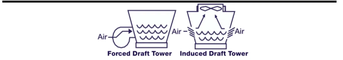
Central cooling systems generate heat that must be rejected outside the building, a cooling tower is commonly used for this purpose. All cooling towers function as large heat exchangers, transferring heat from the condenser side of the chiller to the outside air by spraying the hot water through a flow of outside air. This flow of outside air is created with centrifugal or axial fans mounted at the lower end of the tower in the forced-draft tower.
A more common type of tower, the induced-draft tower, utilizes a propeller fan at the top of the tower to pull air up through the tower. The induced-draft tower offers better aerodynamics and is generally more efficient than a forced-draft tower. The forced-draft tower is generally quieter and requires less space than an induced-draft tower, but operates at a lower efficiency. Both forced-draft and induced-draft cooling towers (Figure 3) employ a surface contact medium or fill to increase contact surface and improve the transfer of heat between hot water from the chiller and the outside air.
Figure 3: Cooling Tower Types
Forced Draft Tower Induced Draft Tower
Scaling, corrosion, and biological growth all impede tower efficiency and increase maintenance costs from the resultant condenser fouling and loss of heat transfer. Chemical treatment is generally used to mitigate these problems. However, new, non-chemical water treatment technologies, such as ozone generators, magnetic systems, and ultraviolet irradiation, are available. Ozone is a powerful oxidant and biocide that can replace chemicals completely in some cases. Magnetic systems are designed to cause scale-forming minerals to precipitate in a low-temperature area away from heat exchanger surfaces, thus producing non-adherent particles. The precipitated particles can then be removed by blowdown, mechanical means or physical flushing. The effectiveness of a magnetic system can be diminished by a low ratio of dissolved calcium to silica, by the presence of excessive iron in the water, or if it is installed in close proximity to high-voltage power lines.
Two-speed fan motors in combination with fan cycling provide an improvement in control and efficiency over fan cycling alone. VSDs provide the most efficient method of control. Cooling tower fans offer similar energy-saving opportunities. Fan power is proportional to the cube of the airflow rate; thus, a reduction of 20 percent in fan airflow (and speed) will correspond to a reduction of 49 percent in fan power.
EN E R G Y ST A R® Buildings Manual 9 HEATINGAND COOLING SYSTEM UPGRADES 99999
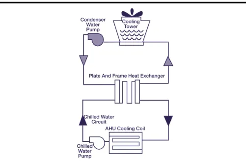
Free Cooling (Water Side Economizer)
Under the right conditions, free cooling or a water side economizer system can generate significant energy savings. In cooler, drier climates, water side economizers can provide over 75 percent of the cooling requirements; in warmer climates they may provide only 20 percent. Although air side economizers, as discussed in Stages Three and Four, are typically less expensive, you should also consider using a water side economizer.
Several methods of free cooling are available. The most common method is a type of indirect free cooling that uses a separate heat exchanger, typically of the plate-and-frame type. It allows for a total bypass of the chiller, transferring heat directly from the chilled water circuit to the condenser water loop (see Figure 4).
A less common method is direct free cooling, in which the condenser and chilled water circuits are linked directly without the use of a separate heat exchanger. A disadvantage of using direct free cooling is that bacteria present in the cooling tower water system (described above) may contaminate your chilled water circuit. You can, however, install filtration systems or strainers to minimize this risk.
Facilities that require year-round cooling from high sensible heat gains would most likely benefit from direct free cooling. A large computer room or data center cooled with a central chilled water system would be a promising application.
When ambient outdoor conditions are ideal (that is, when the wet-bulb temperature is low enough), the chiller can be shut off and the cooling load may be served exclusively by the cooling tower without the energy-intensive mechanical refrigeration. The resulting reduction in energy consumption can be dramatic.
Figure 4: Indirect Water Side Economizer
Condenser Water Pump Cooling Tower Chilled Water Pump Chilled Water Circuit
AHU Cooling Coil Plate And Frame Heat Exchanger
EN E R G Y ST A R® Buildings Manual 10 HEATINGAND COOLING SYSTEM UPGRADES 1010101010
Pumping System Upgrades
In buildings that use pumps to transport chilled water or condenser water, an
integrated system approach can reduce pumping system energy by 50 percent or more. You can make your pumping systems more energy-efficient by:
• Replacing oversized impellers, pumps, and motors with rightsized pumps and smaller, energy-efficient motors.
• Installing VSDs on pump motors.
• Converting single-loop configurations to primary-secondary loop configurations.
Rightsizing
Rightsizing pumps to accommodate lower maximum loads can result in energy savings of up to 70 percent. The most cost-effective method is often trimming or replacing an oversized impeller in an existing centrifugal pump. When pump rightsizing, maximum design capacity of the new impeller or pump must be greater than the measured maximum load for the system. Be certain that the new motor is an energy-efficient model, sized to meet the maximum load, and recognize that pump motors, like fan motors, come in incremental sizes (5 hp, 7.5 hp, 10 hp, etc.).
Calculate your energy savings from rightsizing by comparing rated energy curves at various loads for old and new pump and motor sizes. Contact the pump manufacturer or an engineering consultant for further assistance.
Variable-Speed Drives
Installation of VSDs will ensure that your pumps are performing at maximum efficiency at part-load conditions. (See page 10 for an example of VSD savings potential.) Similar to the fan systems, the power required to operate a pump motor is proportional to the cube of the speed. For example, in a pump system with a VSD, a load reduction that results in a 10-percent reduction in motor speed reduces energy consumption by 27 percent [1 – (0.9)3 = 0.27].
EN E R G Y ST A R® Buildings Manual 11 HEATINGAND COOLING SYSTEM UPGRADES 1111111111
Estimating Savings From Installing VSDs On Pumps
To estimate the annual energy savings you can gain from installing VSDs on pumps, you will need to estimate run times for all part-load conditions, based either on monitoring or load calculations. Compare the motor horsepower of the existing motor with the motor horsepower of the motor with a VSD installed under the part-load conditions. The difference in horsepower (converted to kW) multiplied by the operating hours for the range of load percentages will give you the expected energy savings in kWh. Example:
A 30-hp VSD is installed on a chilled-water pump. The existing flow rate is 1,040 gallons per minute (GPM), existing operating hours are 3,300 per year, and the pump’s energy consumption is 66,900 kWh per year. The initial cost of the VSD is $7,175.
The VSD reduces average flow to 700 GPM. Estimated new annual energy consumption:
(66,900)(700 ÷ 1,040)3 =
20,400 kWh per year. Estimated annual energy savings:
(66,900 – 20,400)($0.08/kWh) = $3,720 per year. Simple payback =
$7,175 ÷ $3,720 = 1.9 years.
When installing VSDs, be sure to:
• Complete harmonic, power factor, and torsional analyses before installation. • Conduct a coast-down test to compare mechanical resonance with speed response. • Ensure that maximum and minimum flow rates through the chiller can be met
with chiller pump upgrades.
Single-Loop Conversions
The rated minimum flow for chilled water through the chiller is typically 70 percent of maximum, which also applies to VSD flow reductions. However, a primary-secondary loop configuration, also known as a production-distribution configuration, can allow for greater energy savings without compromising your chiller performance. With the primary-secondary loop configuration (see Figure 5), chillers are equipped with smaller chilled-water pumps, or primary pumps. These are constant-flow pumps that operate with a lower pressure drop than in a single-loop configuration. Variable-flow secondary pumps then distribute the chilled water through your building’s end-use air-handling devices and have the capability of reducing their speed at part-load conditions.
When converting from a single-loop configuration to a primary-secondary configuration, be sure to:
• Pipe the lower velocity chiller bypass water on the production side to flow into the higher velocity chilled water return on the distribution side and not vice versa.
EN E R G Y ST A R® Buildings Manual 12 HEATINGAND COOLING SYSTEM UPGRADES 1212121212
• Replace three-way valves at air-handling unit coils with two-way valves. • Maintain maximum and minimum flow rates through the chiller. Figure 5: Primary/Secondary Pumping Loop
Central Heating Systems: Best Opportunities
Boiler System Upgrades
Approximately 40 percent of all commercial buildings use boilers for space heating (see Figure 6). Of these, roughly 65 percent are gas fired, 28 percent are oil fired, and 7 percent are electric. The combustion efficiency of older boilers is generally between 65 percent and 75 percent, although inefficient boilers can have efficiencies between 40 percent and 60 percent. Energy-efficient gas- or oil-fired boiler systems can have efficiencies between 85 and 95 percent.
Figure 6: Boiler Components
Primary Loop Chiller
VSD Pumps Secondary Loop
Building Cooling Load
Fire Tubes Flue Combustion Gas Burner Furnace
EN E R G Y ST A R® Buildings Manual 13 HEATINGAND COOLING SYSTEM UPGRADES 1313131313
Boiler system energy consumption can be reduced by 10 to 30 percent. Improve your boiler system’s efficiency by either:
• Replacing your existing boiler system with a new, rightsized, more energy-efficient boiler system.
• Retrofitting your boiler so that it can perform more efficiently.
Boiler Rightsizing
The best opportunities for energy savings come with replacing an old or inefficient boiler with a more efficient boiler system. Energy-efficient boilers have increased heating surface areas and improved controls for fuel and airflow over the range of load conditions. Before replacing your boiler:
• Determine your building’s heating load and rightsize your boiler accordingly.
• Plan to rightsize your boiler with an energy-efficient model.
• Determine the applicability of converting from a single-boiler system to a staged system of smaller, energy-efficient boilers operating in combination.
To determine whether you should replace your boiler system, you need to understand your building’s heating load and your existing boiler’s efficiency. Calculate the energy savings from replacing a boiler by comparing rated energy consumption at various loads for the old and new boiler systems. Contact the boiler manufacturer or an engineering consultant for further assistance.
Boiler Retrofit
Retrofitting existing boilers can dramatically improve the peak- and part-load efficiency of your boiler and extend the useful life of your heating systems. Your best options include:
• New Burners—Efficient burners improve fuel combustion and reduce emissions of nitrogen oxide.
• Temperature/Pressure Reset—
Temperature and pressure reset controls provide significant energy savings by minimizing fuel waste. Reset controls match the supply of steam with the demand for heat instead of supplying steam at a higher pressure than is needed. The system water temperature is reset based on the outdoor temperature. If outdoor temperature increases, the system water temperature is lowered.
• Boiler Economizer—A boiler economizer captures waste heat in the exhaust flue gases and uses it to preheat the boiler feedwater. When natural gas fuels the boiler, it is important to maintain the stack temperature at a minimum of 250°F to avoid condensation of the water vapor in the flue gases. The figure below shows the percentage of fuel saved as a function of the percentage of excess air for
EN E R G Y ST A R® Buildings Manual 14 HEATINGAND COOLING SYSTEM UPGRADES 1414141414
different stack temperatures from a gas-fired boiler. For example, with the use of an economizer, a boiler operating at a stack temperature of 500°F and 80 percent excess air would realize a 7 percent fuel savings (see Figure 7).
• Baffle Inserts—Baffle inserts induce combustion gases to flow in a turbulent spiral pattern, which increases the efficiency of heat transfer.
Figure 7: Boiler Economizer Fuel Energy Savings
Source: Turner, Energy Management Handbook, 2nd ed.
As discussed in Recommissioning, improved operation and maintenance are important parts of your overall strategy and can provide significant energy savings. An annual tune-up, improved water treatment, and a preventative maintenance program can reduce boiler energy waste by as much as 15 percent.
Furnace Upgrades
Furnaces are heating plants that produce heat for the purpose of providing thermal comfort for your building. The heat source can be fuel oil, natural gas, electricity, coal, or wood. The main components of a warm-air furnace are the heat exchanger, fuel burner, blower or fan, controls, and housing.
An integrated system approach can reduce your furnace energy consumption 5 percent to 25 percent. You can make your furnace energy-efficient by:
• Replacing your existing furnace with a new, rightsized, energy-efficient furnace. • Retrofitting your furnace with additional controls so that it can perform more
efficiently.
Excess Air (%)
Fuel Energy Savings (%)
25 20 15 10 5 0 20 40 60 80 100 120 140 160 180 800° F 700° F 600° F 500° F 400° F 0
EN E R G Y ST A R® Buildings Manual 15 HEATINGAND COOLING SYSTEM UPGRADES 1515151515
Furnace Rightsizing
Standard combustion furnaces have a steady-state efficiency of about 80 percent. High efficiency furnaces built with condensing heat exchangers have a steady-state efficiency as high as 94 percent. If your furnace is more than 10 years old, you should:
• Measure your heating loads.
• Evaluate your existing furnace in terms of efficiency and capacity.
• Determine the benefits of installing a new, rightsized energy-efficient model.
Furnace Retrofit
Retrofitting existing furnaces can significantly increase your energy savings. Your best options are to:
• Install new burners—Efficient burners improve fuel combustion and reduce emissions of nitrogen oxide.
• Install two-stage setback controls—In electrically heated spaces where the temperature is reduced during unoccupied periods, the electric demand needed to bring the space back to its original temperature can be significant. In this case, if your electric rate structure includes demand charges, install a two-stage setback thermostat with staged supplemental heat and a programmable demand limiter to prevent demand peaks in the morning. Consider alternatives to resistance heating to reduce heating costs and overall impact on the environment.
As discussed in Recommissioning, improved operation and maintenance of your systems save energy—often in significant amounts. As with boiler systems, an annual tune-up and a preventative maintenance program are crucial to achieving and sustaining these savings.
Unitary Systems: Best Opportunities
Unitary systems are factory-assembled cooling, or combined heating and cooling, systems. Cabinet- or skid-mounted for easy installation, typical units generally consist of an evaporator, blower, compressor, condenser, and, if a combined system, a heating section. The size of the units ranges from approximately 1.5 to 130 tons.
Typical unitary systems are single-packaged units, split-system packaged units, heat pump systems, and water-source heat pump systems. Compared to central chiller plants, unitary systems do not last as long (only 12 to 15 years) and are less efficient. Unitary systems are generally used in one-, two-, or three-story buildings that have small cooling loads, such as retail spaces, small office buildings, and classrooms. Generally speaking, it is not feasible to convert a building from packaged units to central chilling. However, it is not always necessary to replace in kind. (See the heat pump and additional strategies sections for conversion options, pages 18 and 19.)
EN E R G Y ST A R® Buildings Manual 16 HEATINGAND COOLING SYSTEM UPGRADES 1616161616
Whether your building uses unitary systems for cooling, heating, or both, you can benefit from an integrated system approach. Depending on the upgrades you have implemented in tune-ups through fan systems, cooling load requirements have probably been reduced between 10 percent and 40 percent.
As with chillers, existing unitary systems are, in many cases, oversized. Likewise, unitary systems that are in poor condition suffer downtime and significantly increased operating and maintenance costs. A new and more reliable unitary system may be more cost effective. If your unitary systems are 10 years old or older, you can realize energy savings by replacing unitary systems with rightsized, energy-efficient models.
Rightsizing
Rightsizing your unitary systems to maximize the benefits of the cooling and heating load reductions can result in significant energy savings. When determining the rightsizing potential of your unitary system, be sure to measure your cooling and heating loads first. By knowing what your cooling and heating loads are, you will be better able to rightsize your new unitary system to meet maximum loads.
To estimate your energy savings from rightsizing, first measure your cooling and heating loads. Then, using the seasonal energy efficiency ratio (SEER) for your old and new systems, compare their respective energy consumption. Contact your equipment manufacturer or an engineering consultant for further assistance. Typically, commercial buildings use unitary systems with cooling capacities greater than 5 tons. In some cases, however, due to space requirements, physical limitations, or small additions, residential-sized unitary systems are used. In these cases, be sure to look for the ENERGY STAR label. The ENERGY STAR label is found on various high
efficiency heating, cooling, and control products and can help you differentiate between these and standard efficiency products. To determine what products may meet your needs, visit the ENERGY STAR Web site at http://www.energystar.gov/
products/
The information about the technologies listed below will help you better understand your unitary system and recent technological advances that may increase its rightsizing potential.
• Packaged or rooftop units • Vertical packaged units • Split-system packaged units • Air-source heat pumps
EN E R G Y ST A R® Buildings Manual 17 HEATINGAND COOLING SYSTEM UPGRADES 1717171717
Packaged Or Rooftop Units
Packaged units are packaged HVAC units that are usually mounted on the roof, freeing up valuable indoor floor space. They can also be installed on a concrete pad at ground level. Because they are self-contained, manufactured units, installation costs are low.
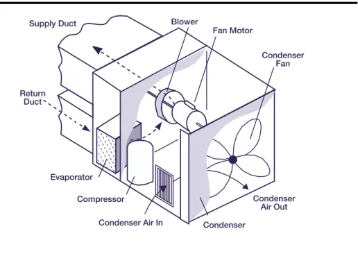
Single-package units consist of a blower section, filter bank, evaporator coil, at least one compressor (larger units typically have multiple compressors to improve load matching), and an air-cooled condenser section (see Figure 8). Units may also come equipped with a heating section.
Heating is accomplished using either natural gas or electricity; however, natural gas is generally less expensive, depending on the region. Heat pump systems can be used in situations where electricity is the only source of energy. Unitary heat pump units typically range in size from 1.5 to 20 tons. Heat pump systems are discussed further below.
As packaged units age and deteriorate, their efficiency often decreases while the need for maintenance increases. Upgrading your packaged units to high efficiency models will result in substantial long-term energy savings.
Figure 8: Self-Contained Packaged AC Unit
Supply Duct
Return Duct
Evaporator
Compressor
Condenser Air In Condenser
Condenser Air Out Condenser Fan Blower Fan Motor
EN E R G Y ST A R® Buildings Manual 18 HEATINGAND COOLING SYSTEM UPGRADES 1818181818
In the last 10 to 15 years, manufacturers have made significant improvements to the efficiency of packaged units. The efficiency of heat transfer at both the evaporator and condenser coils has been improved; high efficiency motors are now standard; and blower and compressor designs have improved in high efficiency packaged units. Scroll compressors are now commonplace on medium-sized (20- to 60-ton) rooftop units. Energy efficiencies of newer units have a SEER in the range of 9.50 to 13.0. It is not uncommon to find older units operating at efficiencies as low as 6.0, and most operate at less than 9.0. Gas-fired heating sections typically have an annual fuel utilization efficiency (AFUE) of about 80 percent.
Case Study: Installing High Efficiency Packaged Units Can Cut Energy Costs
For a typical 100,000-sf office building that has 10 standard 25-ton packaged units with a SEER rating of 9 and 80 percent electric heat efficiency, electricity costs would be about $71,300 per year ($53,300 for cooling and $18,000 for heating, at $0.08 per kWh).
Installing a new energy-efficient unit with a cooling energy efficiency rating of 13 would result in cooling mode electricity costs of about $36,900 annually—a savings of $16,400 per year. If the heating component of the system was improved to 90 per-cent efficiency, the heating savings would be $2,000 per year. The combined annual savings of $18,400 equals a reduction in energy costs of more than 25 percent. (The cooling units are assumed to operate for 2,000 hours per year, while the heating
units are assumed to run for 1,000 hours per year.)
All newer packaged rooftop units are equipped with factory-installed microprocessor controls. These controls make maintaining equipment easier and improve the energy efficiency of both the unit and the overall HVAC system. Control features include temperature setback and on/off scheduling. Large systems have variable air volume capability, as discussed in Fan System Upgrades. Also, most units have an optional communication interface for connection to an EMS system.
Vertical Packaged Units
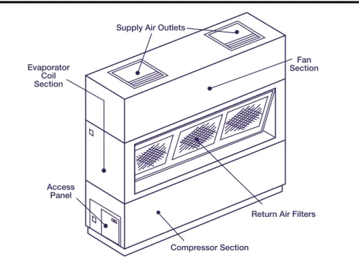
Other unitary systems, if upgraded to high efficiency systems, offer much the same potential for energy savings. Vertical packaged units (see Figure 9), which are a variation on the packaged unit, are typically designed for indoor installation. Most units have a water-cooled condenser, which can be fed from a cooling tower and/or city water. Other components are mounted in the package. Ductwork can be connected to the unit to distribute the air.
Split-System Packaged Units
Split-system packaged units (see Figure 10) have an outdoor pad or rooftop-mounted air-cooled condenser. Refrigerant piping connects the compressor section to an indoor air-handling unit and evaporator coil.
EN E R G Y ST A R® Buildings Manual 19 HEATINGAND COOLING SYSTEM UPGRADES 1919191919
Unless they are heat pump type units, they cannot provide heat to the space. Heating coils can be installed in the air-handling section, particularly if there is a central source of heat such as hot water or steam from a boiler.
Figure 9: Vertical Packaged Units
Figure 10: Split-System Packaged Units
Supply Air Outlets
Evaporator Coil Section Access Panel Compressor Section
Return Air Filters Fan Section To Space Blower Evaporator Compressor Condensor Refrigerant Lines
EN E R G Y ST A R® Buildings Manual 20 HEATINGAND COOLING SYSTEM UPGRADES 2020202020
Air-Source Heat Pumps
Air-source heat pump systems are typically rooftop units, packaged either complete or as split systems. During cooling mode, the unit operates as a typical air-conditioning system. During heating mode, the cooling system is reversed completely to extract heat from the outside air and to provide it to the space. The size of unitary heat pump systems ranges from approximately 1.5 tons to 20 tons. In some cases, existing
packaged cooling units with electric resistance heat can be upgraded to heat pumps for improved energy efficiency.
Heat pump applications are best suited to relatively warm climates, such as the Southeastern United States, and to areas where the availability of natural gas for heating is low. . When temperatures are low, the coefficient of performance (COP) of the heat pump falls dramatically. A 7.5-ton rooftop heat pump unit that has a high-temperature COP of 3.0 can have a low-high-temperature COP of 2.0 or less. Moreover, when the temperature drops further, heat pumps require supplemental heat, typically electric resistance; thus, effective heating efficiencies become even lower. More recently, dual-fuel heat pumps have become available in areas where natural gas can be used as the supplemental heating source.
Split-package heat pumps are designed with an air-handling unit located inside the conditioned space, and both the condenser and compressor are packaged in units for outdoor installation on a pad or on the roof.
Due to their improved annual efficiency, air-source heat pumps are good candidates for replacing packaged cooling units with electric-resistance heating coils.
Water-Loop Heat Pump Systems
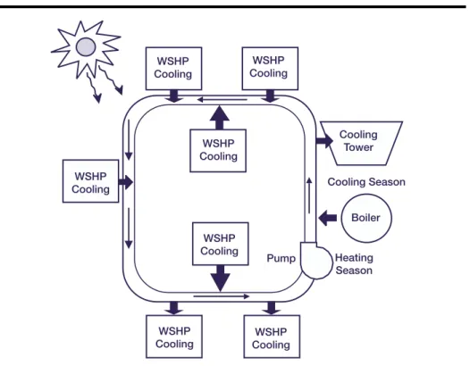
Water-loop, or water-source, heat pump systems use water instead of air to transfer heat. In an air-to-air heat pump system, heat is removed from indoor air and rejected to outside air during the cooling cycle. The reverse happens during the heating cycle. However, in a water-loop heat pump, water replaces the outdoor air as the source or sink for heat, depending on the cycle in use.
In hot weather, a cooling tower removes heat from the water loop; in cooler weather, a central boiler heats the water.
As shown in Figure 11, water-loop heat pump systems allow for simultaneous heating and cooling by multiple separate and distinct units, and thus increase individual comfort. Furthermore, recovering heat from cooled areas and recycling it into other areas adds to the system’s efficiency.
The size of water-source heat pumps ranges from approximately 0.5 tons to 25 tons. Efficiencies of water-source units are generally higher than their air-to-air
EN E R G Y ST A R® Buildings Manual 21 HEATINGAND COOLING SYSTEM UPGRADES 2121212121
efficiency water-source heat pumps have a SEER as high as 14.0 to 15.0 and a COP as high as 4.4.
Figure 11: Water-Loop Heat Pump System
Additional Strategies: Best Opportunities
In addition to the strategies outlined in previous sections, other worthwhile
technological strategies warrant further attention for some applications. Whether or not these strategies are viable for your building depends upon various conditions (for example, size, location, types of business onsite, utility rate structures). These strategies include the following:
Heating and Cooling Strategies
• Geothermal heat pumps • District heating and cooling • Radiant heating and cooling
Cooling Strategies
• Cool storage
• High temperature difference distribution
WSHP Cooling WSHP Cooling WSHP Cooling Cooling Tower Cooling Season Boiler Pump Heating Season WSHP Cooling WSHP Cooling WSHP Cooling WSHP Cooling
EN E R G Y ST A R® Buildings Manual 22 HEATINGAND COOLING SYSTEM UPGRADES 2222222222
• Evaporative cooling • Non-electric cooling
Geothermal Heat Pumps
An additional strategy for improving the efficiency of your HVAC equipment is the geothermal heat pump. Geothermal heat pumps take advantage of the natural heat stored underground to provide space conditioning heating, cooling, and humidity control. Rather than converting chemical energy to heat, as in a furnace, geothermal heat pumps work by moving heat. During the heating season, a geothermal heat pump can move heat taken from the ground and apply it to a building. In the cooling season, this process is reversed, as the building’s excess heat is moved back to the ground to provide air conditioning. (See A Short Primer and Environmental
Guidance for Geothermal Heat Pumps, EPA 430-K-97-007, available from
1-888-STAR YES).
Due to the relative stability of ground temperature, geothermal heat pump systems are inherently more efficient than air-source heat pumps, which rely on outside air as the medium which receives heat from the heat pump or from which heat is extracted by the heat pump. Geothermal heat pump systems provide the highest efficiencies in both cooling and heating seasons, as well as in heating water.
Information on geothermal heat pump systems is available from the ENERGY STAR
Web site at http://www.energystar.gov/products/, under the Heating and Cooling for your home. For additional information, visit the Geothermal Heat Pump
Consortium Web site at http://www.ghpc.org/home.htm.
District Heating and Cooling
District cooling is a shift in the generation location of chilled water from inside a facility to a local chilled-water producer. As a district cooling customer, your facility would purchase chilled water from a generation plant just as you purchase power from a local utility company. Chilled-water plants supply water to a number of customers within the plant district territory, usually encompassing a radius of three to five city blocks.
There are several advantages to district cooling:
• Most district cooling plants are modern facilities that use energy-efficient generation methods.
• The need for buildings to own and use refrigerants is eliminated along with refrigerant compliance responsibilities, handling regulations, rising replacement costs, and capacity-loss issues.
• Ice can be generated at off-peak hours (when utility demand and rates are lowest) and used at peak cooling periods to supplement chilled-water
EN E R G Y ST A R® Buildings Manual 23 HEATINGAND COOLING SYSTEM UPGRADES 2323232323
production, yielding a lower chilled-water temperature. This lower temperature means that high temperature-difference distribution may be viable, as discussed below.
• Chilled water can be purchased without the expense of installing, operating, or maintaining one’s own chiller.
This strategy is applicable for some facilities in cities, campuses, or industrial parks. District heating and cooling eliminates central heating and/or cooling equipment. Also, because district cooling suppliers use modern, non-CFC chillers, CFC chiller equipment in your building can be retired.
Radiant Heating And Cooling
Radiant heating and cooling, also called hydronic heating and cooling, differs from standard HVAC design in that it uses water distribution instead of air distribution to meet a building’s heating and cooling needs.
In a radiant cooling system, cold water is pumped through special panels or grids of tubing mounted in the walls, ceilings, or floors. These panels absorb heat from the building and bring it back to the HVAC plant to be removed from the building. As discussed in load reductions and fan systems, the amount of outdoor air required to ventilate your building is actually much smaller than the amount of air that must be circulated through cooling coils to handle cooling load. Radiant systems cool the space directly, reducing your ventilation system to the size required to bring in outside air. This requirement is about 20 percent of the total air recirculation capacity of the average building. As water has a much higher capacity to store heat or cold than air, a much smaller volume of water can be circulated, further reducing costs. Radiant cooling can supply the same cooling capacity as other systems but at levels of energy consumption that are typically about 75 percent of those for air-based systems.
Cool Storage
Cool storage is a means of using less expensive off-peak power to produce cooling for the building. Cool storage is based upon the principle that a storage medium can be cooled while chiller operating cost is low, and the storage can be discharged when chiller operating cost is high. Furthermore, chillers tend to be most economical to operate at night, when building cooling loads are low, electric rates may be lower, and lower outdoor temperatures allow the chiller to reject heat more efficiently. Cooling energy is stored in tanks of water, ice and water, or water circulating around chemical modules that freeze and thaw. This last system, as well as an ice-based
EN E R G Y ST A R® Buildings Manual 24 HEATINGAND COOLING SYSTEM UPGRADES 2424242424
system, has the advantage of taking up less space than chilled-water storage because the freezing process can naturally store much more “cold” in a given volume.
Generally, the most cost effective type of cool-storage design and operating strategy is the partial-storage system shown in Figure 12. A partial storage system reduces a building’s maximum electrical demand by shifting a portion of the cooling load from daytime to nighttime. The total chiller capacity required for the building is also less than that of a standard system.
The cost effectiveness of cool-storage systems varies considerably depending on the specific application. However, high electric-utility peak-demand charges, which generally coincide with the peak cooling period in the afternoon, and a time-of-use rate with a low nighttime kWh charge are factors that make it favorable to shift cooling equipment operation away from the utility peak period. A cool storage system is most cost effective when its capital cost is viewed as an incremental cost compared to replacing or constructing a new chilled-water system.
Figure 12: Partial-Storage Strategy
Source: E SOURCE, Commercial Space Cooling Technology Atlas.
High Temperature-Difference Distribution
Designing or modifying the chilled water distribution system to have a lower supply temperature and a higher return temperature than normal provides more cooling capacity for the same amount of chilled water flow. Increasing the difference between the supply and return temperatures by a certain percentage reduces the required water flow by the same percentage. Such a reduction in chilled-water flow can substantially reduce required pumping energy.
Because a chiller operates less efficiently as it supplies colder chilled water, high temperature-difference distribution systems are most appropriate when combined with
24-Hour Period
T
ons
Load
Chiller Capacity Chiller Charging Storage Chiller Meets Load Directly Storage Meets Load
EN E R G Y ST A R® Buildings Manual 25 HEATINGAND COOLING SYSTEM UPGRADES 2525252525
cool-storage systems, as discussed above. To reduce the required tank size, cool-storage tanks containing ice or water are generally at lower-than-standard supply temperature. High temperature difference distribution systems are most cost effective in new construction, because reduced chilled water flow requirements reduce the capital cost of pumps, piping, and heat exchangers.
Evaporative Cooling
The process of evaporating water or another fluid absorbs heat, just as a kettle must be heated before the water must boil. This is the basis for many types of mechanical cooling. A much simpler and more economical variation can be used in some climates. Cooling is produced by passing a flow of dry air over a wet surface. As the water evaporates from the surface, the air stream is cooled. Although evaporative cooling systems are most effective in dry climates, where the air has a large capacity to absorb evaporating water, they can also be used elsewhere to reduce the annual cooling load on mechanical refrigeration equipment.
There are both direct and indirect types of evaporative coolers and systems used in conjunction with mechanical refrigeration. Direct evaporation systems evaporate water directly into the supply air stream, whereas indirect systems cool one air stream that in turn cools the supply air stream through a heat exchanger. Although indirect systems are more costly, they avoid increasing the humidity of supply air. Evaporative cooling can also be used to precool air to reduce the load on a mechanical refrigeration system. Mechanical refrigeration can be used to increase the evaporative cooling capacity by cooling the water used for evaporation.
Compared with standard unitary air-conditioning equipment, indirect evaporative coolers have been shown to use 70 percent less electricity seasonally. While evaporative cooling equipment generally offers reduced cooling capacity compared to mechanical refrigeration, indirect evaporative precooling can supply half of the annual cooling load in many areas (ASHRAE, 1999, Applications Handbook, Chapter 50).
Nonelectric Cooling
While the most common cooling plants use an electric motor to drive a refrigerant compressor, there are nonelectric alternatives, such as engine-driven, steam turbine-driven, and absorption chillers. While nonelectric cooling systems are often less expensive to operate, their first cost is higher than that of electric systems, and they come with increased equipment size and maintenance costs.
Gas engine-driven chillers are a cost-effective option for producing chilled water in areas where gas rates are lower than electric rates. Gas engine-driven chillers are much like electric chillers, except that they contain an engine rather than a motor. Where there is a need for heating during the cooling season, heat recovery from both the
EN E R G Y ST A R® Buildings Manual 26 HEATINGAND COOLING SYSTEM UPGRADES 2626262626
exhaust and cooling water can improve the efficiency of these systems. Gas engine-driven chillers have average operating COPs of 1.7 to 1.9. If heat recovery from the exhaust and water jacket are implemented, their efficiency can increase to 2.3 COP. While the efficiency of gas engine-driven chillers is much lower than that of electric chillers, total fuel use and pollution emissions can be comparable when considering electric power plant operations. The centrifugal or screw chiller driven by the engine uses an HCFC or HFC refrigerant, much like an electric chiller.
Absorption chillers do not use the vapor compression cycle that most mechanical refrigeration uses; instead, they are “driven” by heat, not by a mechanical drive input. Moreover, they use water as a refrigerant in conjunction with lithium bromide as the absorption chemical (or ammonia and water) such that there is no ozone-depletion potential from the system. Although the system has fewer moving parts than a centrifugal chiller, it is technically complex.
There are single- and double-effect absorption systems, and they may be fired directly with a gas burner or indirectly with steam generated by separate equipment. Single-effect systems have a COP of 0.5 to 0.7. Double-Single-effect systems are more efficient, with a COP of 1.0 to 1.1. Triple-effect absorbers are also under development and promise still better efficiency. In addition, chiller-heaters, which use absorption technology to provide cooling, heating, or both cooling and heating as required, are available. Steam turbines can be used to drive centrifugal compressors. The chilled medium is usually water or brine, with a halogenated hydrocarbon refrigerant. Other refrigerants such as ammonia, butane, or propane are also used in industrial processes.
Summary
This section has described numerous opportunities for optimizing both the size and efficiency of your building’s heating and cooling systems. Before undertaking any of these strategies, you should measure your building’s heating and cooling loads. Having done so, retrofit or rightsize your heating and cooling equipment based on the load reductions implemented in tune-ups through fan systems.
To find the most efficient equipment for your building’s cooling and heating systems, consult the American Council for an Energy-Efficient Economy’s (ACEEE’s) Guide To
Energy-Efficient Commercial Equipment, 2nd edition.
Next Steps
Measure your cooling and heating loads and complete the Heating and Cooling Survey at the end of this document.
EN E R G Y ST A R® Buildings Manual 27 HEATINGAND COOLING SYSTEM UPGRADES 2727272727
Cooling Systems
• Estimate your savings by conducting a Heating and Cooling survey and working with an engineer (on-staff or consultant) to calculate savings potential.
• Rightsize your cooling system to take advantage of load reductions.
• Eliminate CFC refrigerants from your chiller system by retrofitting or replacing your chiller.
• Older chillers represent an investment opportunity. Install new high efficiency chillers to reduce operating costs and match equipment size to cooling load. • Improve cooling towers and install VSD controls with rightsized pumps. • Implement cooling system efficiency strategies such as free cooling.
Heating Systems
• Replace older boilers and furnaces or upgrade components and controls of existing units.
Unitary Systems
• Replace older unitary equipment with high efficiency equivalents or heat pumps.
Additional Strategies
• When evaluating your upgrade options, assess whether your building’s specific characteristics lend themselves to:
– Geothermal heat pumps – District heating and cooling – Radiant heating and cooling – Cool storage
– High temperature-difference distribution – Evaporative cooling
EN E R G Y ST A R® Buildings Manual 28 HEATINGAND COOLING SYSTEM UPGRADES 2828282828
A
PPENDIX
: H
EATING
AND
C
OOLING
S
URVEY
Measure Heating and Cooling Loads To Rightsize Systems
This survey will familiarize you with the condition of your heating and cooling systems and enable you to determine whether your heating and cooling equipment needs replacing with rightsized, energy-efficient equipment.
To prepare to rightsize your heating and cooling systems, compile basic information and measurements about the systems and your facility. Next, calculate the required cooling and heating loads for your building.
To get started, recruit a survey team including a building engineer, HVAC technician, boiler operator, and electrician. You will need to evaluate your available staff resources and staff capabilities. If you do not have the means of taking these measurements, you may want to contact an independent testing, adjusting and balancing (TAB) firm or seek outside engineering services.
Before You Begin
You will need the following items to complete your survey:
• The latest specifications for the heating and cooling equipment in your building. • The TAB report for your building’s pumping systems.
• “As built” mechanical drawings.
• Operations and maintenance manuals for the boiler, chiller, or unitary system equipment.
• The system logs showing hot and chilled water supply and chilled-water return temperatures and flow rates (if you have an energy management system). • A data logger (note: for unitary systems only).
EN E R G Y ST A R® Buildings Manual 29 HEATINGAND COOLING SYSTEM UPGRADES 2929292929
Chiller Systems Survey
Collect the following information:
Chiller Type(choose one) ❑ Air-cooled centrifugal
❑ Water-cooled centrifugal ❑ Reciprocating ❑ Helical rotary/screw ❑ Steam absorption ❑ Hot-water absorption ❑ Direct-fired absorption ❑ Engine-driven Manufacturer ________________________________________ Type of Refrigerant __________________________________ Age _________________________________________________ Efficiency (kW/ton) ___________________________________ Size or Capacity (in tons) _____________________________
(12,000 Btu/hr = 1 ton)
Calculate the maximum cooling load for your building using the following
proce-dure:
What is the maximum cooling load for the building (in tons)? This load will be compared with the chiller capacity recorded above. To determine maximum cooling load, take the following measurements in the afternoon on a typical hot summer day to capture peak load effects on your system. Note: An energy management system may also log these measurements.
• Temperature of the chilled-water supply (CHWS). A temperature gauge should be found on the pipe at the chiller’s supply outlet.
• Temperature of the chilled-water return (CHWR). A temperature gauge should be found on the pipe at the chiller’s return inlet.
• Flow rate (GPM) of the chilled water supply. A flow rate gauge should be found on the supply pipe. If a gauge is not available, the design flowrate from as-built drawings may be used.
Chilled Water System Measurements
Temperature of CHWS ___________ Temperature of CHWR __________ Flow rate (GPM) of CHWS _______
EN E R G Y ST A R® Buildings Manual 30 HEATINGAND COOLING SYSTEM UPGRADES 3030303030
Now, using the measurements, do the following calculations: CHWR – CHWS = ∆T:
∆T x 500 x (GPM ÷ 12,000) = Load (in tons):
Load x 1.1 = Maximum Cooling Load
How much of your existing chiller capacity does your building currently need? To answer this, do the following calculation:
Maximum Cooling Load ÷ Chiller Capacity =
Percentage of Chiller Capacity Needed
If the required capacity of the chiller is 30 percent less than the installed capacity of your existing chiller, you should seriously consider replacing the chiller. The efficiency of the chiller decreases sharply below 70 percent loading. Also, remember that the chiller is operating most of the time at part-load conditions with your newly reduced loads, which increases your rightsizing potential even further.
Boiler Systems Survey
Collect the following information:
Heating Plant Central hot waterType boiler
Manufacturer ___________________ Fuel (gas, oil, electric) ___________ Age ___________________________ Efficiency (percent) ______________ Size or Capacity ________________ (in MBtu/hr)
Calculate the maximum heating load for your building using the following
procedure:
What is the maximum heating load for the building (in MBtu/hr)? This load will be compared with the heating system capacity recorded above. To determine maximum heating load, take the following measurements in the morning on a typical cold winter day to capture peak load effects on your system. Note: An energy management system
may also log these measurements. The following procedure is tailored to typical central
hot water boiler systems.
• Temperature of the hot water supply (HWS). A temperature gauge should be found on the pipe at the boiler’s supply outlet.
EN E R G Y ST A R® Buildings Manual 31 HEATINGAND COOLING SYSTEM UPGRADES 3131313131
• Temperature of the hot water return (HWR). A temperature gauge should be found on the pipe at the boiler’s return inlet.
• Flow rate (GPM) of the hot water supply. A flow rate gauge should be found on the supply pipe. If a gauge is not available, the design flow rate from as-built drawings may be used.
Boiler System Measurements Temperature of HWS ____________ Temperature of HWR ____________ Flow rate (GPM) of HWS _________
Now, using the measurements, do the following calculations: HWR – HWS = ∆T
∆T x 500 x GPM/1,000 = Load (in MBtu/hr) Load x 1.1 = Maximum Heating Load
How much of your existing boiler capacity does your building currently need? Maximum Heating Load ÷
Heating Plant Capacity =
Percentage of Heating Capacity Needed
For other types of heating systems, there are other ways of measuring maximum heating load.
• For systems such as forced-air furnaces and heat pumps that respond to
thermostats by cycling on and off, a simple runtime meter will show how much of the time the unit cycles on. Supply-temperature data logged every few minutes by an EMCS or other data logger can also be analyzed to determine how much of the time the unit is cycled on. The percentage of heating capacity needed is the time the unit operates divided by the total time during a high heating load period. • Measuring steam boiler loading is similar, but more complicated than for a hot
water boiler. Instead of the water flow rate, the steam flow rate must be measured. Instead of multiplying a temperature difference by a factor accounting for the heat content of each GPM, the temperature and pressure properties of the supply steam must be recorded from gauges on the supply line and used to determine the heat content of each pound of steam using a steam table.
EN E R G Y ST A R® Buildings Manual 32 HEATINGAND COOLING SYSTEM UPGRADES 3232323232
Other strategies for measuring heating loads include: • Periodic gas meter readings
• Oil tank gauge readings or oil deliveries
• On/off cycle times for systems that operate intermittently
Unitary Systems Survey
Collect the following information for each type of unit installed in your building:
Boiler System MeasurementsUnitary System Type ❑ Packaged rooftop unit
(choose one) ❑ Split system
❑ Vertical packaged unit
❑ Heat pump
Manufacturer ____________________________________________ Htg Fuel (gas, oil, elec.) ___________________________________ Unit Age ________________________________________________ Cooling Efficiency (%) ____________________________________ Heating Efficiency (%) ____________________________________ Size or Capacity (cooling) _________________________________
(in tons)
Size or Capacity (heating) _________________________________ (in MBtu/hr)
Calculate the maximum cooling and heating loads for your building using the
following steps:
What are the maximum heating and cooling loads for the building (in MBtu/hr)? These loads will be compared with the cooling and heating capacities recorded above. To determine maximum heating or cooling load use the procedure described in the heating section for small systems that cycle on and off.
Time cycled on ÷ Total time = Percentage of Capacity Needed