GSA SECURITY CRITERIA
Building Technologies Division
Office of Property Development
Public Buildings Service
General Services Administration
DRAFT Revision
October 8, 1997
GENERAL TABLE OF CONTENTS
Part 1
THE CRITERIA
Chapter 1
General Requirements
Chapter 2
Site Planning and Landscape Design
Chapter 3
Architecture and Interior Space Planning
Chapter 4
Structural Engineering
Chapter 5
Mechanical Engineering
Chapter 6
Electrical Engineering
Chapter 7
Fire Protection Engineering
Chapter 8
Electronic Security
CHAPTER 1 GENERAL REQUIREMENTS 1.A. Purpose
1.B. Security Design Philosophy 1.C. Applicability
1.D. Security Risk Assessment System 1.D.1 Protection Levels 1.D.2 Risk Analysis
1.D.3 Assessment Framework 1.D.4 Project-Specific Assessment 1.E. Intelligence Sharing
1.F. Planning
1.F.1 Crime Prevention Through Environmental Design CPTED) 1.F.2 Capability to Increase Security
1.F.3 Concept of Tiered Defensive System 1.F.4 Interdisciplinary Approach
1.F.5 Adjacent Sites
1.F.6 Site Security Requirements 1.F.7 Stand-off
1.G. Life-Cycle Costing 1.H. Co-location 1.I. Child Care Centers 1.J Parking
1.K Waivers 1.L. Design Criteria
1.L.1 Moving vehicle bomb
1.L.2 Stationary exterior vehicle bomb
1.L.3 Attacks on the exterior of a facility at close range 1.L.4 Small arms
1.L.5 Forced entry at the building envelope 1.L.6. Unauthorized entry
1.L.7 Visual surveillance 1.L.8 Acoustic eavesdropping 1.L.9 Electronic eavesdropping 1.L.10 Mail bombs
1.L.11 Medium and large size package or supply bombs 1.L.12 Airborne contamination
1.L.13 Small package bombs in uncontrolled public areas, prior to screening 1.L.14 The introduction of explosives beyond controlled areas by individuals with authorized access
1.L.15 Stationary vehicle bomb 1.M Classification
1.M.1 Criteria as a public document 1.M.2 Criteria for limited official use
CHAPTER I GENERAL REQUIREMENTS
1.A Purpose
GSA developed these PDS security planning and project development criteria to ensure that security becomes an integral part of the planning, design, and
construction of new Federal facilities and major alteration projects. The criteria consider security in all building systems and elements, and are intended to complement PBS-PQ100.1, The Facilities Standards for the Public Buildings Service.
Based on the work of GSA and other agencies’ staff, as well as architects, planners, and specialty consultants, this document represents the best thinking of a multi-disciplinary group of professionals with recognized security expertise. 1.B Security Design Philosophy
The primary goal of these criteria is to save lives and prevent injury, and
secondarily to protect Federal buildings, functions, and assets. The criteria focus on detecting, deterring, and delaying terrorist and criminal attacks through
planning, programming, design, access control, and engineering measures. In the event of a major terrorist or criminal act, structural, mechanical, electrical, and life-safety criteria are aimed at facilitating safe evacuation and rescue and early recovery of the facility.
The criteria take a balanced approach to security, considering cost effectiveness, acknowledging acceptance of some risk, and recognizing that Federal buildings should be not bunker- or fortress-like, but open, accessible, attractive, and representative of the democratic spirit of the country. Prudent, rather than excessive, security measures are appropriate in facilities owned by and serving the public.
Security design requires a multi-disciplinary approach and coordination among professionals. Yet most design professionals are not trained to incorporate
security into design, and most security professionals are not trained in architecture and engineering. The need to include security features in most building systems requires effective communication between all professionals beginning at the pre-conceptual stage of each project.
1.C Applicability
The GSA-PDS security planning and project development criteria, which are above and in addition to existing GSA criteria, apply to all new GSA projects and major building alteration projects. The criteria may also apply to long-term (10-years or more) leased constructed buildings. Unique facilities, such as those
classified by the Department of Justice’s Vulnerability Assessment as Level V, are not included.
1.D Security Risk Assessment System
The following is a methodology for determining security and risk levels. As soon as possible, this method should replaced with a long term, more valid, and more cost effective risk management system. See 1.E for a discussion of the long term system. Also, see Limited Official Use Design Criteria, Chapter 1, for the specific threats and risks being considered.
1.D.1 Protection Levels
The Protection Levels described in this chapter and in Chapter 4 do not use size or population as the only factors. The Protection Levels are performance levels and more closely resemble those already in use by GSA. The GSA criteria describe expected building damage states in such scenarios as earthquakes and bomb blast and give a reliable and meaningful way to evaluate the performance of existing buildings which do not conform to building code provisions intended to limit damage. There is no direct correlation to protection levels defined in this criteria and the building classes in the Department of Justice Vulnerability Assessment (I, II, III, IV, V).
For planning purposes, a building’s elements (architectural, structural, mechanical, etc.) may be separately assigned to one of five protection levels, depending on the need for security. When appropriate, the entire building may be assigned to a protection level. These levels in the context of costs are as follows: E = Very High Level: this level not within the scope of these criteria.
D = High Level: protection requires significant, costly security measures. This category is rarely assigned.
C = Medium High Level: protection requires costly security measures.
B = Low Level: protection requires security measures of moderate additional cost. A = Low Level: protection requires security measures of little additional cost. 1.D.2 Risk Analysis
For each facility element (or entire facility), a protection level is assigned on the basis of a risk analysis that considers the following definitions:
• Symbolic Importance: Some facilities are highly visible symbols of this country, either nationally, regionally, or locally. The Alfred P. Murrah Federal Building, for instance, was the primary symbol of the U.S.
Government in Oklahoma City. Among symbolic structures, some represent critically important government missions. From a terrorist’s point of view,
the more symbolic the targeted structure, the more impact an attack will have and the more publicity the attack will receive.
• Criticality: This measures the degree to which a building houses operations and functions critical to national interests of the United States. Examples of very critical activities may include foreign affairs, defense activities, the national airspace system, critical materials, etc. Less critical activities may include judicial activities, law enforcement agencies, government records, national records, and personnel information. The lowest level of criticality may involve functions similar to those performed in commercially owned buildings.
• Consequence: This measures the impact of an attack on a facility, including injuries and the loss of life; damage to the property or assets; interruption of the work done at the facility; and the time needed to repair, replace, or bypass the building in order to continue the work.
• Threat: These are classified as either terrorist threats, including bombs, chemical attacks, and biological attacks, or crime threats, based on local crime indexes. Terrorist threats are identified through intelligence on the
capabilities and aims of terrorists and the probability of an attack. This information can come either through existing inter-agency working groups or through the creation of a new group.
• Verified Threat: A threat can be regarded as verified if there is threat information authenticated by an official intelligence or law enforcement agency based on highly trusted sources or methods, and included information that a specific location or agency will be attacked within a contemporary time frame. A threat may also be verified if reasonably reliable information of a threat has been received from two, or more, independent sources through intelligence or law enforcement channels. Great care needs to be taken to guard against false confirmation, by which the same source’s information is reported by two different agencies and the source is not identified by one or both agencies.
• High Consequences: High consequences can be defined as the manifested effects of a criminal or criminal-like event that would involve the loss of life or the causation of injuries at to-be-defined levels. High consequences may also be the loss of, or damages to, tangible or intangible assets or the loss of irreplaceable assets and resources, all of which have significant worth on a national scale. Worth is not limited to monetary considerations. As one example, the loss of an old Spanish Mission in California may have little monetary impact, but may have great historical significance.
• Symbol: In the context of this study only, a symbol involves any thing or place for which there is a popular recognition of an object, name, or
governmental activity by virtue of its historic significance, its size, its
uniqueness, or its context with specific ideas or sets of values or attitudes. A clear example would be the Statue of Liberty or the Liberty Bell. As another example, a street named Martin Luther King would have symbolic
significance to a racist. Some symbols may have local or regional significance, but little recognition of a nation level.
1.D.3 Assessment Framework
Protection categories combined with threat and risk analyses provide a framework for assessing the extent and cost of security. The following is such a framework for protecting against a terrorist threat:
• Use Protection Level D when a building element or building needs a high level of protection. This would tend to be used when a building is a national symbol or of critical importance; and when its damage or loss will have high consequences; and when there is a verified high threat.
• Use Protection Level C when a building element or building needs a medium-to-high level of protection. This would tend to be used when a building is a regional symbol or has a significant impact on the government’s mission; and when its damage or loss will have high consequences; and when there is a verified threat.
• Use Protection Level B when a building element or building needs a medium-to-low level of protection. This level would tend to be used when the building is a regional symbol or has an impact on the government’s mission; and when its damage or loss will have moderate consequences; and when there is a suspected threat.
• Use Protection Level A when the building element or building does not need higher protection. This level would tend to be used when the building is of low consequence and when there is an unknown threat.
The following can provide a similar framework when protecting against a crime threat:
• Use Protection Level D when there is a high crime index; when the building houses critical operations; or when it has high asset value.
• Use Protection Level C when there is a medium crime index; when the building houses sensitive operations; or when it has moderate asset value.
• Use Protection Level B when there is a low crime index; when the building houses routine operations; or when it has low asset value.
• Use Protection Level A when the facility is small and has a very low crime index; when the building houses routine operations; and when it has very low asset value.
1.D.4 Project-Specific Assessment
A security risk assessment must be done for each new or major alteration project at the earliest stages of project programming and schematics. First, the facility must be categorized for crime and terrorist threats, as above. Then a panel of security, blast, intelligence, and technical experts must conduct a review of the rating. This will ensure the application of appropriate and cost-effective security measures, and give the design team building-specific security criteria to work with..
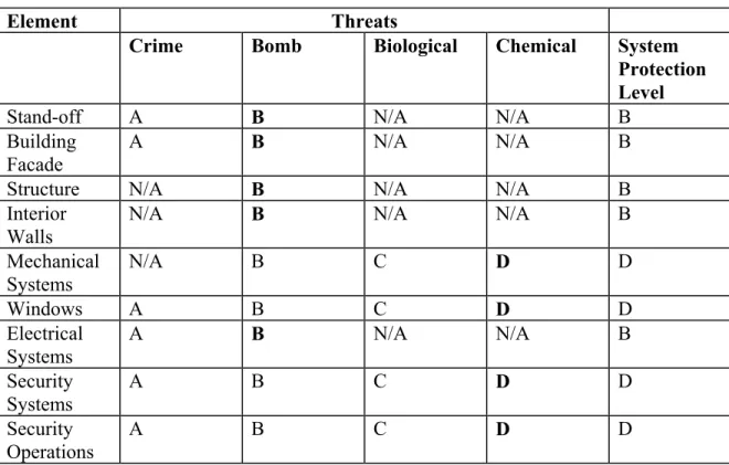
A facility may have different performance categories applied to each of its building systems. Table 1-1 shows the determination for a hypothetical facility with a low crime threat, limited bomb threat, verified biological threat (moderate consequence) and a verified chemical threat (high consequence). The highest level of threat along a horizontal plane dictates the level of protection for that building security element. Once each building element is assigned a performance level, designers can find corresponding protective measures in the engineering criteria that meet the specified performance.
Table 1-1 Determination of Elemental Protection Level Element Threats
Crime Bomb Biological Chemical System Protection Level
Stand-off A B N/A N/A B
Building Facade
A B N/A N/A B
Structure N/A B N/A N/A B
Interior Walls
N/A B N/A N/A B
Mechanical Systems N/A B C D D Windows A B C D D Electrical Systems A B N/A N/A B Security Systems A B C D D Security Operations A B C D D
1.E Intelligence Sharing
Since good intelligence is essential for accurate threat analysis, information that affects GSA building security should be shared through an inter-departmental committee.
The Interagency Security Council’s working group on intelligence could serve this function, or a new group could be formed. Sharing information about threats would improve decision-making, be a more cost effective use of resources, improve security in Federal buildings, and reduce Federal employees’ fears. Action is required to better harness information currently in the government’s possession.
1.F Planning
1.F.1 Crime Prevention Through Environmental Design (CPTED)
CPTED techniques shall be used as much as possible to help prevent and mitigate attacks. Good strategic thinking on CPTED issues such as site planning,
perimeter definition, sight lines, lighting, etc. can eliminate some of the need for engineering solutions.
1.F.2 Capability to Increase Security
Designs shall include the ability to increase security in response to a heightened threat. More costly or inconvenient measures, such as prohibiting parking, shall be implemented as needed.
1.F.3 Concept of Tiered Defensive System
When possible, given the site to build on, try to follow a tiered defensive system with zones of intensifying security beginning at the perimeter and moving to the building’s core. The possible tiers include (a) the perimeter fence or wall, (b) the stand-off distance, (c) the building’s exterior walls, and (d) screening/access control area, and safe interior areas.
1.F.4 Interdisciplinary Approach
Each building system and element shall support risk mitigation and be designed to reduce casualties, property damage, and the loss of critical functions. Security shall be considered in all decisions, from selecting architectural materials to placing trash receptacles to designing redundant electrical systems.
In order to control open space adjacent to Federal facilities, consideration shall be given to acquiring adjacent sites or negotiating for restrictions in or control of rights-of-way. This becomes particularly important when adjacent sites affect the application of these security criteria.
1.F.6 Site Security Requirements
Site security requirements, including stand-off, should be developed before a site is acquired and the PDS is finalized. These requirements may be used to prevent the purchase of a site that lacks necessary features, especially sufficient size, and to help reduce the need for more costly mitigation such as blast design.
Stand-off distance is defined as the distance from the center-of-gravity of a bomb to the face of the closest protected structure. The stand-off distance must be defended through barriers or other means (see 1.M.1).
1.F.7 Stand-Off Distances
For Protection Level D buildings, a stand-off distance of 100 feet should be a planning goal. The preferred design criteria for Level D specifies a 100 foot stand-off, and for Level C, a 20 foot stand-off from all parking, or compensating design measures.
1.G Life-Cycle Costing
In accordance with PQ100.1, these security criteria use life-cycle cost analysis. This allows the selection of materials and systems based on long term value rather than first cost. The impact of initial expenditures upon security-related operating costs can be significant. Security expenditures can also increase or decrease facility productivity. By way of providing a relative measure of this cash flow to the government, one year’s salaries and operating expenses can about equal the entire cost of constructing a new facility.
1.H Co-location
Agencies that are functionally similar or that require similar levels of protection should be housed in the same location. High risk tenants, such as law
enforcement agencies, should not be located with lower risk tenants. If co-location can not be avoided, high risk tenants should be segregated from publicly accessible areas.
1.I Child Care Centers
Child care centers may be located anywhere in low risk buildings. In medium to high risk buildings and courthouses, they should not be within 100 feet from the
main public entrance or a loading dock. They should also be placed 100 feet away from public parking unless there are compensating blast design measures. 1.J Parking
Parking facilities represent considerable risks, with potential for both terrorist attacks on buildings and criminal attacks on individuals. Public parking shall not be allowed under any GSA facility covered by these criteria. Depending on the protection level, parking by various employees shall either be disallowed or controlled. Curbside parking shall similarly be prohibited or controlled. 1.K Waivers
Waivers of these criteria shall be considered through a process to be developed by GSA. Requests for waivers must include persuasive evidence that the security of Federal employees and facilities will not be compromised by a less-than-standard facility. Every effort must be made to meet the security design criteria.
LIMITED OFFICIAL USE
1.L Design Criteria
Aggressors have historically employed a wide range of offensive strategies reflecting their capabilities and objectives. The criteria below categorize these strategies into various tactics. The following is a list of tactics addressed by the criteria in Chapters 2-8.1
1.L.1 To address a moving vehicle bomb (an aggressor drives an explosives-laden car or truck into a facility and detonates the explosives in a suicide attack) (see 2.A.1):
• For A and B Levels, no special construction;
• For C Levels, use stand-off elements designed to stop a W7 vehicle at the maximum practical approach speed up to Y1;
• For D Levels, use stand-off elements designed to stop a W8 vehicle at the maximum practical approach speed up to Y2.
In all cases, terrain and planning of the approaches should be used to limit the speed of approaching vehicles.
1.L.2 To address a stationary exterior vehicle bomb (an aggressor covertly parks an explosives-laden car or truck near a facility, at least 20 feet from the exterior wall, and detonates the explosives by time delay or remote control):
• For A and B Levels, no special construction;
• For C Levels, consider W5 (minimum) in a vehicle parked beyond the curb lane;
• For D Levels, consider W6 (minimum) in a vehicle parked beyond the curb lane.
1.L.3 To address attacks on the exterior of a facility at close range (an aggressor uses weapons such as rocks, clubs, improvised incendiary or explosive devices, and hand grenades in exterior attacks):
LIMITED OFFICIAL USE
1 Material in this section was adapted from a manual produced by Joint Departments of the Army and Air
Force, TM 5--583-1/AFMAN 32-1071, Volume 1 Security Engineering-- Project Development 12 May 1994. Definitions of terms used herein are contained in that training manual. For additional information on mitigation measures and ways of accomplishing the required level of protection, see the training manual.
LIMITED OFFICIAL USE
• For A and B Levels,no special construction;
• For C Levels, design to rocks, clubs, and Molotov cocktails;
• For D Levels, design to rocks, clubs, and improvised incendiary devices.
1.L.4 To address small arms (an aggressor fires various small arms such as 9 mm pistols, submachine guns, shotguns, and rifles from a distance) - glazing only:
• For A and B Levels, no special construction;
• For C and D Levels, use concealment and hardening.
Concealment may include blinds, drapes, reflective film, and other visual barriers.
1.L.5 To address forced entry at the building envelope (an aggressor forcibly enters a facility using forced entry tools, which may include weapons and explosives):
• For A and B Levels, protect against limited hand tools2 - no special construction;
• For C and D Levels, protect against limited hand tools (requires special construction), use CCTV and electronic sensors; consider necessary response time.
1.L.6 To address unauthorized entry (the aggressor attempts to enter a facility by using false credentials or stealth. The aggressor may carry weapons or explosives into the facility):
• For A and B Levels, use locks and alarms;
• For C Levels, use locks and alarms plus electronic access control, intrusion detection, and CCTV;
• For D Levels, use locks and alarms plus electronic access control, screening and intrusion detection, and CCTV.
1.L.7 Address visual surveillance (the aggressor employs ocular and photographic devices such as binoculars and cameras with telephoto lenses to monitor facility operations or to see assets):
LIMITED OFFICIAL USE
LIMITED OFFICIAL USE
• Courthouse only and D Levels. (Requirements to be developed on a project-specific basis by tenants.)
1.L.8 Address acoustic eavesdropping (the aggressor employs listening devices to monitor voice communication or other audibly transmitted
information):
• Courthouse only and D Levels. (Requirements to be developed on a project-specific basis by tenants.)
1.L.9 Address electronic eavesdropping:
• Courthouses only and D Levels. (Requirements to be developed on a project specific basis by tenants.)
1.L.10 To address mail bombs (the aggressor delivers bombs or incendiary devices to the target in letters or packages. The bomb sizes involved are relatively small. The aggressor’s goal is to kill or injure people):
• For A and B Levels, no special construction;
• For C and D Levels, design for W2.
1.L.11 To address medium and large size package or supply bombs (the aggressor conceals bombs in various containers and delivers them to supply and material handling points such as loading docks. The bomb sizes can be significantly larger than those in the mail bombs. The aggressor’s goals are to damage the facility, kill or injure its occupants, and/or damage or destroy assets) (see issue 1.L.13 which deals with building lobbies):
• For A and B Levels, no special construction;
• For C and D Levels design for W4.
1.L.12 To address airborne contamination (an aggressor contaminates the air supply of a facility by introducing chemical or biological agents into it):
• For A, B, and C Levels, no special construction;
• For D Levels, consider low level protection in addition to location of air intake.
LIMITED OFFICIAL USE
1.L.13 To address small package bombs in uncontrolled public areas, prior to screening (the aggressor conceals bombs and delivers them to the lobby. Bomb sizes can be larger than those in the mail bomb tactic):
• For A and B Levels, no special construction;
• For C and D Levels, design for W3.
1.L.14 To address the introduction of explosives beyond controlled areas by individuals with authorized access:
• For A and B Levels, no special construction:
• For C and D Levels, consider W1.
1.L.15 To address a stationary vehicle bomb (an aggressor covertly places a bomb in a government employee’s car, which is then parked in a facility. The aggressor detonates the explosive either by time delay or remote control):
• For A and B Levels, no special construction;
• For C and D Levels, design for W4. 1.M Classification
1.M.1 Except for those pages labeled LIMITED OFFICIAL USE (LOU), the document should be treated as a public document, disseminated via NIBS CD ROM only.
1.M.2 The risks, threats, and critical design criteria described in this chapter shall be for Limited Official Use or limited NIBS distribution. This NIBS distribution would only allow authorized users access to the criteria.
CHAPTER 2 SITE PLANNING AND LANDSCAPE DESIGN
2.A Vehicular Control
2.A.1 Site Perimeter Barriers 2.A.2 Perimeter Vehicle Inspection 2.B Site Lighting
2.C Site Signage 2.D Landscaping 2.E Parking
2.E.1 Parking in Adjacent Streets 2.E.2 Parking on Adjacent Properties
CHAPTER 2 SITE PLANNING AND LANDSCAPE DESIGN
2.A Vehicular Control
Blast pressures from an exploding vehicle bomb decrease exponentially with distance from the explosion. One design strategy to mitigate blast effects is to maintain as much standoff distance as possible between the vehicle bomb and the facility. This will then minimize the amount of strengthening needed against the resulting blast pressures discussed in Chapters 3 and 4. The designer must balance the costs of providing standoff and providing hardening. (See 3.A.1 on designing for blast loads.)
2.A.1. Site Perimeter Barriers
Site perimeter barriers capable of stopping vehicles of the designated sizes for Protection Levels C and D shall be installed. A vehicle velocity shall be used considering the angle of incidence in conjunction with the distance between the perimeter and the point at which a vehicle would likely be able to start a run at the perimeter. A barrier shall be selected that will stop the threat vehicle. Except for the weight and speed of the vehicle, Army TM 5-853-1 and TM 5-853-2/AFMAN 32-1071, Volume 2 contain design procedures to make this selection. In
designing this barrier system, the following should be considered:
• Various types and designs of barriers such as walls, fences, plantings, trees, static barriers, sculpture, and street furniture;
• Designing site circulation to prevent high speed approaches by vehicles;
• Offsetting vehicle entrances as necessary from the direction of a vehicle’s approach to force a reduction in speed.
2.A.2 Perimeter Vehicle Inspection
For Level D, a vehicle inspection sally port shall be provided at the site perimeter with interlocked gates, including vehicle arrest devices on the site side of the sally port gate. A guard house, anti-ram gate barrier, and interlocked gates to prevent tailgating shall be included, as well as a pull-off area inside the sally port. For Level C, there shall be mandatory inspection at the curb line for gross
amounts of explosives. If screening cannot be provided, additional hardening may be required.
2.B Site Lighting
The following site lighting levels shall be provided: at vehicular and pedestrian entrances, 15 horizontal maintained foot candles; for perimeter and vehicular and pedestrian circulation areas, 5 horizontal maintained foot candles. Perimeter
lighting shall be continuous and on both sides of the perimeter barriers, with minimal hot and cold spots and sufficient to support CCTV and other
surveillance. 2.C Site Signage
Confusion over site circulation, parking, and entrance locations can contribute to a loss of site security. Signs shall be provided off site and at entrances; there shall be on site directional, parking, and cautionary signs for visitors, employees, service vehicles, and pedestrians.
2.D Landscaping
Landscaping that permits concealment of criminals or obstruction of views by security personnel and CCTV shall be avoided.
Plants can be used as deterrents to unwanted entry. Site grading can limit access, and berms can be located to deflect explosions. Ponds, lakes, and streams can also be used to prevent vehicle access.
2.E Parking
2.E.1 Parking in Adjacent Streets
Parking is often permitted in curb lanes, with a sidewalk between the curb lane and the building. In dense, urban areas, this may place uncontrolled parked vehicles unacceptably close to a facility in public rights-of-way. Where distance from the building to the nearest curb provides insufficient standoff, parking in the curb lane shall be restricted as follows:
Level A - Allow unrestricted parking;
Levels B and C - Allow government-owned and key employee parking only; Level D - Use the lane for stand-off. Use structural features to prevent parking. For typical city streets this will require negotiating to close the curb lane for Level D.
2.E.2 Parking on Adjacent Properties
The following are recommended minimum stand-off distances between the building and parked vehicles:
Levels A and B - 5 feet; Level C - 20 feet; Level D - 100 feet.
SUMMARY OF CHAPTER 2 - SITE PLANNING AND LANDSCAPE DESIGN
Section A B C D 2.A.1 Vehicular
Control
Not required Not required Install barriers to stop a vehicle of the specified size and speed.
Install barriers to stop a vehicle of the specified size and speed. 2.A.2 Perimeter
Vehicle Inspection Not required Not required Controlled entrances for ratchet up ability.
Install sally port with vehicle arrest devices.
2.B Improve Site Lighting
Yes Yes Yes Yes
2.C Improve Signage to Control Site Circulation
Yes Yes Yes Yes
2.D Avoid Dense Landscaping
Yes Yes Yes Yes
2.E.1 Parking in Adjacent Streets
No restrictions Government and key employees only.
Same as B Prevent parking by using structural features. 2.E.2 Parking on Adjacent Properties
CHAPTER 3 ARCHITECTURAL AND INTERIOR DESIGN 3.A Parking
3.A.1 Perimeter Parking 3.A.2 Internal parking
3.A.3 On Site Adjacent Surface or Structured Parking 3.A.4 Parking Facility Security Systems
3.A.5 Natural Surveillance in Parking Facilities 3.A.6 Stair Towers and Elevators in Parking Facilities 3.A.7 Parking Facility Perimeter Access Control
3.A.8 Surface Finishes and Signage in Parking Facilities 3.B Planning
3.B.1 Office Locations 3.B.2 Mixed Occupancies
3.B.3 Public Toilets and Service Areas 3.B.4 Horizontal Refuge
3.B.5 Loading Docks and Shipping and Receiving Areas 3.B.6 Retail in the Lobby
3.B.7 Public Areas not Subject to Screening 3.B.8 Stairwells
3.C Access Control
3.C.1 Public Screening 3.C.2 Employee Screening 3.C.3 Personnel Access Control
3.C.4 Combining Public and Employee Entrances 3.C.5 Bands of Security
3.D Child Care Centers
3.D.1 Facilities Housing Child Care Centers 3.D.2 Locations Within Facilities
3.D.3 Further Child Care Center Security Measures 3.E Interior Construction
3.E.1 Mailroom
3.E.2 Lobby Doors and Partitions
3.E.3 Walls, Floors, and Ceilings Enclosing Critical Building Components 3.F Exterior Doors and Walls
3.F.1 Forced Entry 3.F.2 Employee Entrances
3.F.3 Garages and Vehicle Service Entrances 3.G Additional Features
3.G.1 Areas of Potential Concealment 3.G.2 Roof Access
CHAPTER 3 ARCHITECTURE AND INTERIOR SPACE PLANNING
3.A Parking
3.A.1 Perimeter Parking
Chapter 2 describes measures to keep parked vehicles away from buildings, and Chapter 4 gives blast design criteria. In the event that cars are not kept at a sufficient distance, increased hardening measures shall be required. The extent to which the site design is successful in keeping threats away from the building determines the amount and cost of blast design required.
This criterion may be in conflict with on site parking requirements. In addition, there may be costs or regulatory obstacles to removing street parking. These factors need to be considered in the decision to use blast criteria in lieu of parking restrictions.
3.A.2 Internal Parking
Internal parking shall be restricted as follows:
Levels A and B - Government vehicles and employees of the building only; Level C - Selected government employees only;
Level D - Selected government employees with a need for security.
3.A.3 On Site Adjacent Surface or Structured Parking Adjacent surface parking shall be restricted as follows: Levels A and B - No restriction;
Level C - Within 50’ of the building, government vehicles and employees only; public parking preferably not closer than 100’;
Level D - 100’ minimum stand-off to parking. 3.A.4 Parking Facility Security Systems
Parking security systems have two features: passive and active. Passive security features are a physical part of the design of the facility (i.e., lighting). Active security measures invoke a response by the management and/or employees of the facility (i.e. , security patrols and monitored Closed Circuit Television [CCTV] systems) Active systems are often needed to solve problems created by
constraints on the passive security features. Although active systems are generally not necessary in low risk facilities, the design should provide for later installation of additional security systems as needed.
3.A.5 Natural Surveillance in Parking Facilities
For stand-alone, above ground parking facilities, maximizing visibility across as well as into and out of the parking facility shall be a key design principle for Levels B, C, and D.
The preferred parking facility design employs express or non-parking ramps, speeding the user to parking on flat surfaces.
Pedestrian paths should be planned to concentrate activity to the extent possible. For example, bringing all pedestrians through one portal rather than allowing them to disperse to numerous access points improves the ability to see and be seen by other users. Likewise, concentrating vehicular entry/exits in a minimum number of locations is beneficial. Attended booths or parking offices should be located so that activity at pedestrian and vehicular entry points to the facility can be monitored. Likewise, a security station, if provided, should be located where it is visible to the public and where the attendant can directly monitor entry/exit activity.
During the design process, the structural system of the facility shall be evaluated from the security aspect as well as the engineering aspect. Long span
construction and high ceilings create an effect of openness and aid in lighting the facility. Shear walls should be avoided, especially near turning bays and
pedestrian travel paths. Where shear walls are required, large holes in shear walls can help to improve visibility. Openness to the exterior should be maximized. It is also important to eliminate dead end parking areas as well as nooks and crannies.
Landscaping should be done judiciously so as not to provide hiding places. It is desirable to hold planting away from the facility to permit observation of
intruders. (Protection Levels: A, B, C, and D)
3.A.6 Stair Towers and Elevators in Parking Facilities
Stair tower and elevator lobby design shall be as open as code permits. The ideal solution is a stair and/or elevator waiting area totally open to the exterior and/or the parking areas. If a stair must be enclosed for code or weather protection purposes, glass walls will deter the incidents of both personal injury attacks and various types of vandalism. Potential hiding places below stairs should be closed off; nooks and crannies should be avoided.
Elevator cabs should have glass backs whenever possible. Elevator lobbies should be well-lighted and visible to both patrons in the parking areas and the public out on the street. When enclosure is required, such as in underground
parking garages, an automatic fire door, or for a larger opening, a rolling fire shutter with an access door, can be employed so that the area is wide open during normal use. Either the door or shutter will be closed by a smoke detector when needed instead of a fire rated door that remains closed all the time. (Protection Levels: C and D)
3.A.7 Parking Facility Perimeter Access Control
While natural surveillance (visibility) may be adequate for lower risk situations, higher risk often requires access control. Security screening or fencing can be provided at points of low activity to discourage anyone from entering the facility on foot, while still maintaining openness and natural surveillance. In higher risk cases, a system of fencing, grilles, doors, etc. can be designed to completely close down access to the entire facility in unattended hours, or in some cases, all hours. Any ground level pedestrian exits that open into non-secure areas should be emergency exits only and fitted with panic bar hardware for exiting movement only. (Protection Levels: C and D)
3.A.8 Surface Finishes and Signage in Parking Facilities
Interior walls should be painted a light color (i.e., white or light blue) to improve illumination. Signage should be clear in order to avoid confusion and direct users to their destination efficiently. If an escort service is available, signs should inform users. (Protection Levels: A, B, C, and D)
Table 3-1
SUMMARY OF 3.A - PARKING
Section A B C D 3.A.1 Perimeter
Parking
See Chapters 2 and 4 for perimeter parking criteria and their impact on the building design.
3.A.2 Internal Building Parking Government vehicles and employees of the building Same as A Selected government employees only Selected government employees with the need for security 3.A.3 On-site
Controlled Parking
No restriction Same as A Within 50’, government vehicles and employees only 100’ stand off 3.A.4 Parking Facility Security Systems
Yes Yes Yes Yes
3.A.5 Natural Surveillance in Parking Facilities
Yes Yes Yes Yes
3.A.6 Open Stair Towers and Elevators in Parking Facilities
Not required Not required Yes Yes
3.A.7 Perimeter Access Control No control, but design for future change in level
Same as A Yes Yes
3.A.8 Finishes and Signage
Yes Yes Yes Yes
3.B Planning
3.B.1 Office Locations
Offices of judges or other potentially vulnerable officials shall be placed or glazed so that the occupant cannot be seen from an uncontrolled public area such as a street. Whenever possible, such offices shall be placed facing courtyards, internal sites, or controlled areas. If this is not possible, suitable obscuring glazing or window treatment shall be provided. One such treatment is 9 mm ballistic resistant glass. (Protection Levels: C and D)
3.B.2 Mixed Occupancies
High risk target tenants shall not be housed with lower risk tenants. When this can not be avoided, publicly accessible areas (e.g., IRS, social security,
procurement/contracting offices and agencies) should be clearly separated from potential verified risk targets not needing public access (e.g., ATF, FBI, and most law enforcement and intelligence agencies); the entire facility should be treated as one housing high risk tenants. (Protection Levels: C and D)
3.B.3 Public Toilets and Service Areas
Public toilets, service spaces, or access to vertical circulation systems shall not be located in any non-secure areas, including the queuing area and screening space at the public entrance. (Protection Levels: C and D)
3.B.4 Horizontal Refuge
In high-rise buildings, areas of horizontal refuge should be considered, with communications access to egress stairs, emergency medical supplies cabinet, water and a toilet facility. Spaces shall be separated with 2 hour fire rated smoke partitions. (Protection Level: D)
3.B.5 Loading Docks and Shipping and Receiving Areas
Loading docks and receiving and shipping areas shall be separated by at least 50 feet in any direction from utility rooms, utility mains, and service entrances including electrical, telephone/data, fire detection/alarm systems, fire suppression water mains, cooling and heating mains, etc. As a planning goal, the location of the dock should not cause the vehicle to come under the building. In lieu of this, service shall be hardened for blast. (Protection Levels: B, C, and D)
3.B.6 Retail in the Lobby
Retail concessions shall be prohibited in the lobby prior to the security screening point. (Protection Levels: C and D)
3.B.7 Public Areas Not Subject to Screening
Where retail, service, or other public areas are in the facility but not subject to screening and access control, they shall be outside the main structure of the building. Alternatively, blast design separating these areas shall be provided. (Protection Levels: C and D)
3.B.8 Stairwells
Stairwells required for emergency egress shall be located as remotely as possible from areas where blast events might occur, such as lobbies, parking, and loading areas (see 3.E.3). Wherever possible, stairs shall not discharge into lobbies, parking, or loading areas. (Protection Levels: A, B, C, and D)
Table 3-2
SUMMARY OF 3.B - PLANNING
Section A B C D
3.B.1 Locate Offices Away From Uncontrolled Public Areas
Not required Not required Locate offices in safe sites in the building or treat windows
Same as C
3.B.2 Separate High Risk Agencies
Yes Yes Yes Yes
3.B.3 Do Not Locate Toilets and Service Spaces in Advance of Screening
Not required Not required Yes Yes
3.B.4 Horizontal Areas of Refuge
Not required Not required Not required Yes
3.B.5 Separate Building Utilities From Service Docks or Harden Utilities
Not required Yes Yes Yes
3.B.6 Prohibit Retail Concessions in Lobby Prior to Security
Not required Not required Yes Yes
3.B.7 Restrict Unscreened Retail
Not required Not required Yes, or provide blast design
Same as C
3.B.8 Locate Emergency Stairwells Away from High Risk Areas
Yes Yes Yes Yes
3.C Access Control
3.C.1 Public Screening 3.C.2 Employee Screening
A combination of walk-through metal detectors and x-ray devices (shown in Table 3.3) shall be provided. For public entrances, the equipment shall be
alert; for employee entrances, the equipment shall be installed at Level D with space provided for future need at Level C.
3.C.3 Personnel Access Control
A combination of ID check, electronic access card, and turnstiles (as shown in Table 3.3) shall be provided for both public and employee entrances. Electronic access cards with turnstiles should reduce the amount of labor required to staff the entrances.
Sufficient access lanes shall be provided to avoid significant queuing, or queuing shall be provided at the screening area outside of the building footprint. If this is not possible, the queuing area shall be enclosed in blast-resistant construction. Applicable ADA provisions shall be adhered to.
The capacity shall be provided to add vapor and other detection systems if they become part of Federal security criteria (see Chapter 8).
3.C.4 Combining Public and Employee Entrances
Combining public and employee entrances for buildings can have a significant life-cycle cost impact because there will be fewer guards required at entrances. If possible, minimize the number of entrances to realize this savings.
3.C.5 Bands of security should be provided in increasing levels, beginning at the perimeter and moving to the most protected areas at the core. Depending upon the need for security, this would include some or all of the following zones:
• Perimeter (curb lane, adjacent sites, or closest surface parking);
• Standoff (distance from perimeter to the building exterior wall);
• Exterior wall (structure and cladding);
• Screening/access control (public, employee, and service);
Table 3-3
SUMMARY OF 3.C - ACCESS CONTROL
Section A B C D
3.C.1 Public Screening Systems
Not required Future capability for walk-through and x-ray Walk-through detectors, parcel x-ray Same as C 3.C.2 Employee
Screening Not required Not required Provide future capability Walk through and x-ray screening 3.C.3 Personnel
Access Control
Not required ID Check only or turnstile/electron ic access card Turnstile, electronic access cards, and ID check Same as C plus capability for future vapor detector 3.C.4 Combining Public and Employee Entrances
Not applicable Combine where possible Combine where possible Consider combining, depending upon security needs 3.C.5 Intensified Bands of Security
Yes Yes Yes Yes
3.D Child Care Centers
3.D.1 Facilities Housing Child Care Centers
Child care centers located in high risk facilities and courthouses shall have compensating blast design measures unless the center meets all of the following conditions.
3.D.2 Locations Within Facilities
Acceptable locations for C and D Levels include:
• On or near the ground floor, but not within 100 feet of a public entrance or loading dock. Outdoor playgrounds should also be 100 feet from any vehicle location. Acceptable outdoor areas may include side or rear yards and enclosed courtyards, when these comply with other criteria;
• On the upper floors of a building that is more than 3 stories in height. When placing centers on elevated slabs, compensating blast design measures should be taken, and for high risk buildings, the center shall preferably be co-located with the area designated for horizontal refuge.
Locations in the basement, while possibly safe, are not judged acceptable because of the lack of natural daylight and windows providing exterior views.
3.D.3 Additional Security Measures, Policies and Procedures
A separate drop-off and pick-up site shall be provided that is not used for any other building entrance purpose.
Between the child care center and the mail room or other high hazard area, there shall be blast resistance for a medium package device of the specified threat size. Play areas shall be separated from all parking and walkways with a fence that is at least 48 inches high.
Laminated glass or monolithic thermally tempered glass shall be used for all new construction. For additional criteria concerning windows see 4.B.5 and Table 4-1.
Access to the center shall be limited to staff, authorized users and approved visitors only.
There should be designated parking for staff, authorized users and approved visitors.
A 10-minute response time for medical, police and fire department support will be the standard.
Strict lock and key procedures will be maintained at all centers.
Table 3-4
SUMMARY OF 3.D - CHILD CARE CENTERS
Section A B C D
3.D.1 Child Care Centers in
Courthouses
Yes Yes Depending upon location Depending upon location 3.D.2 Child Care Centers in Other Facilities
Not applicable Yes Depending upon location
Depending upon location
3.D.3 Separate Entrances
3.E Interior Construction 3.E.1 Mailroom
The basic design strategy is to detect delivered bombs before they explode. If a threat exists, x-ray all incoming packages and place any suspect letters or packages in a container for others to handle.
Space for disposal containers shall be located in the outside corner of the mailrooms. The mailroom shall be located at the perimeter away from facility entrances, high personnel density, and areas containing critical services, utilities, distribution systems, and other assets. Near the loading dock may be a preferred location. An off-site location may be cost effective in some areas. See Chapter 4 for hardening criteria related to mailrooms.
3.E.2 Lobby Doors and Partitions
Where screening and access control are performed to preclude introduction of weapons into a building, an adversary may bring a weapon into the pre-screening area. For Levels C and D, doors and walls along the line of screening security shall be 9 mm ballistic resistant.
3.E.3 Walls, Floors, and Ceilings Enclosing Critical Building Components Assuming that the building has structurally survived a bomb blast, evacuation and rescue are the most important concerns. It is also important to restrict the
movement of toxic gasses throughout the building.
When closer than 50 feet in any direction to any main entrance, vehicle
circulation, parking, or maintenance area, the walls, floors, and ceilings for the following types of spaces shall be as specified in Table 3-5 for the specified threats:
• Emergency generator;
• Main switchgear;
• Telephone distribution and main switchgear;
• Fire pumps;
• Building Control Centers;
• UPS systems controlling critical functions;
• Main refrigeration systems if critical to building operation;
• Elevator machinery and controls;
• Shafts for stairs, elevators, and utilities;
One obvious strategy to lower the costs of this requirement is to locate these systems outside of the blast influence areas.
Table 3-5
SUMMARY OF 3.E - INTERIOR CONSTRUCTION
Section A B C D
3.E.1 Mailroom Provide space for screening and disposal container
Same as A Provide screening and disposal container
Same as C
3.E.2 Lobby doors
and partitions No special requirements Same as A 9 mm ballistic resistance Same as C
3.E.3 Walls, floors, and ceilings enclosing critical building components Not applicable Consider possible events when locating system components; hardening not required Same as B, but place more emphasis upon locations, and consider providing selective blast hardening to systems within 25 feet of threat areas
Design for blast resistance within 50 feet of defined threat areas
3.F Exterior Doors and Walls 3.F.1 Forced Entry
The strategy is to detect aggressors early in the attempt and delay them long enough for a response force to intercept. Four levels of protection are proposed with applicability below. (See Chapter 8 for intrusion detection systems.) Level A Protect against limited hand tools only;
Level B Protect against a wide variety of hand tools. No special
construction; rely on visual detection of entry attempts through all but doors, windows, and other operable openings.
Levels C
and D Protect against a wide variety of hand tools and limited power or thermal tools. Requires special construction to delay or to equal the minimum necessary response time, and a complete detection system. Depending upon the response time, features may include, for example:
Walls: 4” concrete with #5 @ 6” or 8” CMU with #4 at 8”; Doors: 16 ga. hollow metal;
Windows: Plate glass with 4 mil. retention film. 3.F.2 Employee Entrances
Employee entrances, if separate from public entrances, shall be constructed in the same way as public lobbies with respect to the security features (see 3.C and 3.E.2). They shall be capable of instituting screening and access control on short notice.
3.F.3 Garage and Vehicle Service Entrances
All garage or service area entrances for government controlled or employee permitted vehicles that are not otherwise protected by site perimeter barriers shall be protected by vehicle arrest devices capable of arresting a vehicle of the
designated threat size, at the designated speed. This criteria may be lowered if the access circumstances prohibit a vehicle from reaching this speed. See 2.A for a more detailed discussion of this issue.
Table 3-6
SUMMARY OF 3.F - EXTERIOR ENTRANCE
Section A B C D
3.F.1 Forced Entry Protection
Not required Low level of protection Medium level of protection Same as C 3.F.2 Employee Entrances
Same as lobby Same as lobby Same as lobby Same as lobby
3.F.3 Garage or Service Entrance Vehicle Arrest Devices
Not required Yes Yes Yes
3.G Additional Features
3.G.1 Areas of Potential Concealment
For B, C and D Levels, public areas before screening points shall be minimized to reduce the area in which devices can be concealed. Features such as trash
receptacles and mail boxes that can be used to conceal devices shall not be installed. Mail or express box openings shall be restricted to prohibit insertion of packages.
3.G.2 Roof Access
Table 3-7
SUMMARY OF 3.G - ADDITIONAL FEATURES
Section A B C D 3.G.1 Reduce Potential for Concealing Devices in Pre-screening Areas
Not required Yes Yes Yes
3.G.2 Limit Roof Access to
Authorized Personnel
CHAPTER 4 STRUCTURAL ENGINEERING General Approach
4.A General Requirements 4.A.1 Protection Levels 4.A.2 Designer Qualifications 4.A.3 Design Narratives 4.A.4 Compliance 4.A.5 Good Judgment 4.A.6 New Techniques 4.A.7 Methods and References
4.A.8 Structural and Non-Structural Elements 4.A.9 Loads 4.B New Construction 4.B.1 Progressive Collapse 4.B.2 Explosive Threat 4.B.3 Building Materials 4.B.4 Exterior Cladding 4.B.5 Exterior Glazing 4.B.6 Non-Window Openings 4.B.7 Interior Glazing 4.B.8 Parking
4.B.9 Localized Design Areas 4.B.10 Loading Docks
4.B.11 Mail Rooms and Unscreened Retail Spaces 4.B.12 Exitways 4.C Existing Construction 4.C.1 Protection Levels 4.C.2 Progressive Collapse 4.C.3 Exterior Cladding 4.C.4 Exterior Glazing 4.C.5 Interior Glazing
4.C.6 Additions and Modifications 4.D Historic Buildings
4.D.1 Protection Levels 4.E Further Discussion
4.E.1 Protection Level E
CHAPTER 4 STRUCTURAL ENGINEERING
General Approach
The structural engineering criteria focus on protecting people and assets against
explosive attack and also on managing risk and cost. There are three basic approaches to blast design: loads can be reduced, primarily by increasing stand-off; a facility can be strengthened; or higher levels of risk can be accepted. The best answer is often a blend of the three.
These criteria were developed as a response to defined threats that will be separately provided to the designer; the criteria should be continually re-evaluated as threat scenarios change.
NOTE: Section 4.E of this chapter, Further Discussion, contains additional explanations and information related to the structural criteria.
4.A General Requirements 4.A.1 Protection Levels
Entire buildings shall be assigned Protection Levels, according to a facility-specific threat and risk analysis (see Chapter 1 for a detailed discussion). Protection Levels are performance levels; the following are structural damage definitions for each protection level:
• LEVELS A/B: LOW LEVEL OF PROTECTION - Major damage, unrepairable. The facility or protected space will sustain a high level of damage without progressive collapse. Although progressive collapse is prevented, damage is sufficient to cause a question of safety, casualties will occur, and other assets may be damaged. Damaged building components, including structural members, will require replacement. Depending on the scale of the blast damage, its location, and facility characteristics, the facility may be completely unrepairable, requiring demolition and replacement.
• LEVEL C: MEDIUM LEVEL OF PROTECTION - Moderate damage, repairable. Repair is mandatory and possible. The facility or protected space will sustain a significant degree of damage, but the structure will be reusable. Some casualties may occur and assets may be damaged. Building elements other than major structural members may require replacement.
• LEVEL D: HIGH LEVEL OF PROTECTION - Minor damage. The building facility or protected space may globally sustain minor damage with local moderate damage possible. Occupants and assets may incur some injury or minor damage. Repair is advisable. Probability of limited casualties is low.
• LEVEL E: VERY HIGH LEVEL OF PROTECTION: This applies to facilities of the highest national significance and criticality: these are not within the scope of these criteria. However, this Protection Level is discussed in 4.E.1, as a possible alternative for Protection Level D in circumstances of increased threat.
• REPAIRABLE DAMAGE - Damage that is repairable within days to weeks (unless noted otherwise). It implies at least moderate damage and partial evacuation during repairs.
4.A.2 Designer Qualifications
Explosive effects, structural dynamics and blast resistant design are highly specialized requirements. The designer must take into account the various loading conditions based on the needs of each project. The designs and analyses must account for the spatial and temporal variations of blast loading on the structure, the potential combination of effects such as fragments and air blast overpressure, the time dependent loading including, and the non-linear response of the structure in ranges beyond elastic design. Training and experience are these areas is essential to ensure the desired level of protection and cost effective solutions. For buildings designed to meet Protection Level C or D, a blast
consultant must be included as an integral member of the design team throughout all phases of planning and design.
Blast resistant designs and analyses for GSA facilities shall be performed and/or reviewed by qualified personnel. The blast consultant shall have formal training in structural dynamics and shall have demonstrated experience with accepted design practices for blast resistant design and with referenced technical manuals. A minimum of five years of blast resistant design is desired for the lead blast consultant.
4.A.3 Design Narratives
A design narrative and copies of design calculations shall be submitted at each phase, identifying the building-specific responses to the criteria. Blast
requirements must be integrated into the overall building design starting with the planning phase.
4.A.4 Compliance
Full compliance with this document is expected; limited waivers may be given on a case by case basis (see Chapter 1, 1.L).
Users of this document are cautioned to exercise good engineering judgment and care in the application of these criteria. There is no guarantee that specific structures designed in accordance with this document will achieve the desired performance.
4.A.6 New Techniques
Alternative analysis and mitigation methods shall be permitted, provided that the performance level is attained. New and untested methods shall be evaluated by a peer review panel designated by GSA.
4.A.7 Methods and References
All building components requiring blast resistance shall be designed using established methods and approaches for determining dynamic loads and dynamic structural response. Design and analysis approaches shall be consistent with those in the technical manuals (TMs) below. Where not addressed in this document, the TMs shall control.
The following are primary TMs (see 4.E.2 [Item 18] for additional references):
• Air Force Engineering and Services Center. Protective Construction Design Manual, ESL-TR-87-57. Prepared for Engineering and Services Laboratory, Tyndall Air Force Base, FL. (1989).
• U.S. Department of the Army, Fundamentals of Protective Design for Conventional Weapons, TM 5- 855-1. Washington, DC, Headquarters, U.S. Department of the Army. (1986).
• U.S. Department of the Army. Security Engineering, TM 5 853 and Air Force AFMAN 32-1071, Volumes 1, 2, 3, and 4. Washington, DC, Departments of the Army and Air Force. (1994).
• U.S. Department of the Army. Structures to Resist the Effects of Accidental Explosions, Army TM 5-1300, Navy NAVFAC P-397, AFR 88-2.
Washington, DC, Departments of the Army, Navy and Air Force. (1990).
• U.S. Department of Energy, A Manual for the Prediction of Blast and Fragment Loadings on Structures, DOE/TIC 11268. Washington, DC, Headquarters, U.S. Department of Energy. (1992).
4.A.8 Structural and Non-Structural Elements
The priority for upgrades within a structure is based on the relative importance of a member. The following categories are defined for broad types of structural and non-structural elements:
• Primary Structural Elements - the essential parts of the building’s resistance to catastrophic blast loads and progressive collapse, including columns, girders, roof beams, and main lateral resistance system;
• Secondary Structural Elements - all other load bearing members, such as floor beams, slabs, etc.;
• Primary Non-Structural Elements - elements (including their attachments) which are essential for life safety systems or elements which can cause substantial injury if failure occurs, including ceilings or heavy suspended mechanical units;
• Secondary Non-Structural Elements - all elements not covered in primary non-structural elements.
Priority shall be given to the critical elements which are essential to mitigating progressive collapse. Designs for secondary structural elements shall minimize the extent of injury and damage. Consideration shall also be given to reducing the extent of damage and injury from primary as well as secondary non-structural elements.
4.A.9 Loads
Where required, structures shall be designed to resist blast (B) loads. The
demands on the structure will be equal to the combined effects of dead (D), Live (L*), and blast (B) loads shown in the following formulas. Blast loads and dynamic rebound may occur in directions opposed to typical gravity design requirements.
Demand = D+L*+B Demand = D+B
L*= live load as defined in the appropriate Technical Manual, except as noted here.
For purposes of designing against progressive collapse, loads shall be defined as dead load plus a realistic estimate of actual live load. The value of the live load may be as low as 25% of the code prescribed live load.
B = the time-dependent air blast over-pressures which shall be determined using approved methods.
The design shall use ultimate strengths with dynamic enhancements based on strain rates. Allowable responses are generally post elastic.
In addition to the blast loads, structures shall be designed for all loads and load combinations as defined in model building codes.
4.B New Construction
4.B.1 Progressive Collapse3
Designs which facilitate or are vulnerable to progressive collapse must be avoided. At a minimum, all new GSA facilities shall be designed for the loss of one primary vertical load bearing member at the building perimeter for the first 2 floors above grade without progressive collapse. In addition, new facilities with a defined threat shall be designed with a reasonable probability that, if local
damage occurs, the structure will not collapse or be damaged to an extent disproportionate to the original cause of the damage.
In the event of an internal explosion in an uncontrolled public ground floor area, the design shall prevent progressive collapse due to the loss of one primary vertical load bearing structural member, or the designer shall show that the proposed design precludes such a loss. That is, if columns are sized so that threat charge will not cause the column to be critically damaged then progressive collapse calculations are not required.
The following exception to this criterion is allowed:
The requirement may be waived for buildings designed to Level A. If this is done, a written report clearly stating the potential vulnerability of the building to progressive collapse shall be written for use by GSA as a planning tool to reduce vulnerability (see 1.L).
When a waiver is granted, good engineering practices as outlined in 4.E.2 must be followed to amplify the building’s inherent resistance to
progressive collapse.
Discussion: As an example, if an explosive event causes the local failure of one column and major collapse within one structural bay, design mitigating
progressive collapse would preclude the additional loss of primary structural members beyond this localized damage zone (i.e., the loss of additional columns, main girders, etc.). This does not preclude the additional loss of secondary structural or non-structural elements outside the initial zone of localized damage, provided the loss of such members is acceptable for that performance level and that the loss does not precipitate the onset of progressive collapse.
3 Design to mitigate progressive collapse is an independent analysis to determine a system’s ability to resist
structural collapse upon the loss of a major structural element. It is not a part of traditional blast analysis. It is possible, however, that a blast may be the cause of the removal of structural members. ASCE 7-95 describes progressive collapse and offers additional guidelines.
4.B.2 Explosive Threat
Where an explosive threat, as defined by this document, exists, structures shall be designed to resist blast (B) loads in combination with other loads (see 4.A.9). 4.B.3 Building Materials
All building materials and types are allowed which are also acceptable under model building codes. However, special consideration should be given to materials which have inherent ductility and which are better able to respond to load reversals (i.e., cast in place reinforced concrete and steel construction). Careful detailing is required for material such as pre-stressed concrete, precast concrete, and masonry to adequately respond to the design loads. The
construction type selected must meet all performance criteria of the specified Level of Protection.
4.B.4 Exterior Cladding
For Level D only, exterior cladding shall be designed to resist the design loads. Exterior cladding is defined as all exterior veneer, backing, and non-load bearing wall construction, excluding glazing. Exterior shear walls which also function as cladding shall be considered structure and must meet the requirements of 4.B.2. Where cladding is not designed for the design loads, special consideration shall be given to cladding types that reduce the potential for injury (see 4.B.3). 4.B.5 Exterior Glazing
Window systems (glazing, frames, anchorage to supporting walls, etc.) on the exterior facade shall be designed to mitigate the potentially lethal effects of flying glass following an explosive event. This design shall balance the features of the glazing, framing, and attachments with the capacity of the supporting structural walls. That is, the supporting walls, anchorage, and window framing shall be designed to fully develop the capacity of the glazing material selected.