Sridhar Ramamurthy and Andrej Atrens *
Stress corrosion cracking of high-strength steels
Abstract: The mechanisms of stress corrosion cracking
(SCC) and hydrogen embrittlement were recently reviewed by Lynch in this journal. The present review, in contrast, focuses on the rate-limiting step of the SCC of low-alloy high-strength steels in water and particularly focuses on the influence of the applied stress rate on the SCC of low-alloy high-strength steels. Linearly increasing stress tests of low-alloy high-strength steels in distilled water indi-cated that the stress corrosion crack velocity increased with increasing applied stress rate until the maximum crack velocity, corresponding to v II in fracture mechanics tests in distilled water. Moreover, the crack velocity was dependent only on the applied stress rate and was not influenced by the steel composition. The rate-limiting step could be the rupture of a surface film, which would con-trol the rate of metal dissolution and/or the production and transport of hydrogen to the crack tip or to the regions ahead of the crack tip.
Keywords: linearly increasing stress test (LIST); low-alloy
high-strength steel; stress corrosion cracking.
*Corresponding author: Andrej Atrens , Division of Materials, School of Mechanical and Mining Engineering, The University of Queensland, St. Lucia, Queensland 4072, Australia,
e-mail: andrejs.atrens@uq.edu.au
Sridhar Ramamurthy and Andrej Atrens : Division of Materials , School of Mechanical and Mining Engineering, The University of Queensland, St. Lucia, Queensland 4072, Australia; and Surface Science Western, The University of Western Ontario, London, Ontario N6C 0J3, Canada
1 Introduction
Stress corrosion cracking (SCC) can occur in structures and machinery where stressed metallic parts are in contact with an environment (Dietzel, 2001; Fang et al., 2003; Warke, 2002; Winzer et al., 2005). SCC can occur at a stress intensity factor below the fracture toughness, K IC , and at a stress below the yield stress. Examples include high-strength steels in sulfide solutions [sulfide cracking (Pendley, 2010; Rhodes, 2001)], mild steels in caustic solu-tions [caustic cracking (Nakayama, 2007; Rebak, 2006)], and Cu alloys in ammonia [season cracking (Jones, 1992)].
These well-known examples suggest a metal-environment specificity. However, Speidel (1984) suggested that SCC occurs in many environments. Nevertheless, SCC occurs under specific conditions of electrode potential, environ-ment, and material.
SCC leads to fast fracture when the crack length com-bined with the applied load causes the fracture toughness to be exceeded (Gangloff, 2003; Hodge & Mogford, 1979; Kalderon, 1972; Liu & Macdonald, 1997). This reduces the useful strength of a component. Unlike crack growth due to fatigue, SCC has not been incorporated into lifetime predictions owing to the complex nature of SCC. SCC can result in catastrophic failure, such as the steam turbine at the Hinkley Point ‘ A ’ Power Plant in 1969 (Hodge & Mogford, 1979; Kalderon, 1972) and other catastrophic fail-ures (Bennett, 1981; Gangloff, 2003). SCC in steam turbine rotors was a significant problem in the United States (Lyle & Burghard, 1982; Speidel & Bertilsson, 1984). Hence, research on the root causes of SCC was an ongoing effort (Fang et al., 2003; Villalba & Atrens, 2008a). One way of reducing SCC is to use lower-strength steels, which may not be economical. Alternatively, if the influence of the controlling parameters can be understood, it would be possible to quantify SCC crack growth. To understand the influence of various parameters, the mechanism of crack-ing and the rate-controllcrack-ing step should be identified.
This study aimed to identify the rate-limiting step and the processes involved in SCC of low-alloy high-strength steels in water. This review follows on from the recent reviews by Lynch (2012a,b), which focused on the mechanisms of SCC and hydrogen embrittlement (HE). In contrast, the present review focuses on understanding the rate-limiting step and on the SCC of low-alloy high-strength steels. SCC of low-alloy high-high-strength steels exhibits a high dependence of the crack velocity on the yield strength. Speidel (1984) and Speidel and Bertilsson (1984) showed that the crack velocity increased by seven orders of magnitude for quenched and tempered steels when the yield strength was increased from 800 to 1700 MPa (Figure 1 ). The mechanism for this dependence is presently not known.
On the issue of the relevance of using pure water for SCC evaluations of SCC of high-strength steels, research to understand the basics of SCC is best done in the sim-plest environment. If SCC occurs in distilled water, it is important to understand what occurs in distilled water.
It also means that special ions are not needed in the water. It means that chlorides, for example, may not be necessary to cause SCC. In a practical sense, this is also important because it is not possible to stop SCC by removing the “ damaging ion ” out of the solution. The water itself is part of the cause for SCC. The influence of impurities and solute is beyond the primary scope of this review
This work particularly focuses on the use of the lin-early increasing stress test (LIST) (Atrens, Brosnan, Rama-murthy, Oehlert, & Smith, 1993; Atrens & Oehlert, 1998; Oehlert & Atrens, 1998; Salmond & Atrens, 1992; Wang & Atrens, 1996, 2003b, 2004; Winzer, Atrens, Dietzel, Song, & Kainer, 2008; Winzer et al., 2008) to study the influence of the applied stress rate on the SCC of low-alloy high-strength steels. LIST uses smooth tensile test specimens and can be used to study both crack initiation and crack propagation. The use of LIST to study SCC of low-alloy high-strength steels is of interest because much of the SCC research on high-strength steels has been carried out on precracked specimens. LIST can identify the parameters
H2O, deaerated, 100°C 10-4 10-5 10-6 10-7 10-8 10-9 10-10 10-11 600 800 1000 1200 10 15 MnNi 6 3 14 10 CrMo 9 10 (2 1/4Cr-1Mo) 13 X55 MnCr 18 12 17 MnNiV 5 4 11 20 NiCrMo 12 6 9 40 CrMo 14 6 8 X5CrNiCuNb 17 4 (17-4PH) 7 20 MnMoNi 55 (A508) 6 22 NiMoCr 37 (A533-B) 5 17 Mn4 4 41 SiNiCrMoV 7 7 (4340 M) 3 X22 CrNi 17 (SS431) 2 X20 CrMoV 12 1 (SS422) 1 26 NiCrMoV 12 7 (A471)
Tensile yield strength, σy (MPa)
Stress corrosion crack velocity
, ∆ a/ ∆ t (M/s) 1400 1600 1800 DCB, K=30-60 MPa√m
Figure 1 The relationship between the yield strength and the stress corrosion crack velocity for low-alloy high-strength quenched and tempered steels in water at 100 ° C. Steel composition had limited influence on crack velocity, through its influence on the yield strength. Reprinted from Speidel (1984) and Speidel and Bertilsson (1984) with permission from Springer.
that control stress corrosion crack initiation. The study of the influence of the crack tip stress rate has been a neglected area and seems to offer new insights on the kinetics of SCC and possibly may help to identify the rate-limiting step.
The studies by Magdowski (1987b, 1988) and Rieck, Atrens, Ramamurthy, Gates, and Smith (1988) indicated that the SCC mechanism in this system probably varies with temperature. Thus, it is necessary to consider sepa-rately “ high ” and “ low ” temperature regimes of stress cor-rosion for these steels.
Furthermore, much of the experimental work in the literature dealing with SCC in high-strength steels in aqueous environments has been performed in solutions with a significant concentration of ions from a dissolved salt, an acid, or a base. Results from these tests can only be compared with those for pure water when due regard is given to possible changes in cracking induced by this modification of the cracking environment.
This study does not deal with the SCC of mild steel, maraging steel, or pipeline steels. Results from these steels are examined when no results were available from low-alloy high-strength steels. Caution needs to be exer-cised in drawing conclusions from such information.
SCC of high-strength steels has often been attrib-uted to a mechanism of HE (Bath & Troiano, 1972; Brown, 1971; Eliaz, Shachar, Tal, & Eliezer, 2002; Kerns, Wang, & Staehle, 1977; Kortovich & Steigerwald, 1972; Nelson & Williams, 1977; Parkins, 1972; Sandoz, 1972), although some reviewers (Marichev & Rosenfield, 1976; Parkins, 1972) call into question the view that hydrogen is the sole mechanism. Some evidence (Magdowski, 1987b; Magdowski & Speidel, 1988) has highlighted the possibility of SCC being due to anodic dissolution (AD). Another mechanism that has been mentioned is the surface mobility mechanism, proposed by Farina, Duffo, and Galvele (2005b) and Galvele (1993). These mechanisms are discussed in Section 3. In view of the industrial importance of the field and the substan-tial number of recent publications aiming to clarify the operating mechanisms, it is an appropriate time to review present theories. It should be noted that whereas the mechanism of SCC in high-strength low-alloy steels in the high-strength condition is under question, the SCC of low-strength steels is generally attributed to AD (Parkins, 1972).
Low-alloy steels are normally used in the quenched and tempered condition, so a range of strengths can be produced in any steel by heat treatment. This work studied steels that have yield strength > 1000 MPa, and these are considered high-strength steels.
2 Testing methods
This section reviews existing SCC test methods and their relative merits and disadvantages, which led to the devel-opment of the LIST.
2.1 Constant strain test
The specimen is subjected to a constant strain through a restraining frame, and the load relaxation in the speci-men is noted as a function of time. SCC susceptibility is determined by the time to failure and the number of cracks present on the specimen surface. Results from this type of measurement need to be analyzed carefully, as the time to failure depends on the stiffness of the restraining frame and the ductility of the specimen. Hence, this test provides a qualitative measure of SCC (Yoshino, 1983). However, if the time for crack initiation can be consid-ered as a measure of SCC susceptibility, this test has been shown to provide a reasonable measurement (Yoshino, 1983). This test could also be useful in situations where the crack initiation and failure occur within a short period of time, such as in sulfide stress cracking (Yamamoto, Ueno, Higashiyama, Sato, & Hashimoto, 1985). Hence, in many situations, this test has been used as a screening test.
2.2 Constant load test
A tensile specimen is subjected to a constant applied load, and the time to failure is measured. The time to failure includes both the time for crack initiation and the time for the crack to grow to a critical length. This test is repeated at various applied loads, and the time to failure is plotted as a function of the applied load or stress, thus defining the threshold stress ( σ SCC ) below which stress corrosion cracks
do not propagate (Figure 2 ). A disadvantage with this test
Exposure time σSCC
Initial stress
Figure 2 Schematic diagram of time to failure vs. initial applied stress from a series of constant-load SCC tests using smooth tensile specimens.
is the long testing time required to produce a valid mea-surement of threshold stress. Also, the time required for crack initiation and the time for crack propagation cannot be individually estimated. Despite these drawbacks, this test method has been widely applied to study the sulfide cracking (Du, Tao, & Li, 2004), the chloride cracking (Bau-ernfeind, Haberl, Mori, & Falk, 2006; Jin, 1994) and the SCC of high-strength steels (Oehlert & Atrens, 1996).
2.3 Fracture mechanics tests
Precracked fracture mechanics specimens have been widely used to study stress corrosion crack propagation. Precracking eliminates the uncertainty due to crack ini-tiation. The stress corrosion crack velocity is plotted as a function of the stress intensity factor at the crack tip. Typical results are presented in Figure 3 . SCC can be described by two parameters: K ISCC , the threshold stress intensity factor for SCC; and v II , the stress corrosion crack velocity in region II. v II is generally independent of the stress intensity factor, although there are reports of the stress corrosion crack velocity increasing slowly with increasing stress intensity factor (Hirose & Mura, 1984; Nelson & Williams, 1977). There is some disagreement as to whether there is a true threshold for SCC, i.e., a stress intensity factor K ISCC below which SCC does not occur, or whether the crack velocity is simply dependent on stress intensity factor in this region as indicated in Figure 3. It
10-5
10-6
10-7
10-8
10-9 10-8 10-7 Crack tip strain rate (mm/s)
Crack
velocity
(mm/s)
Figure 3 Schematic diagram of stress corrosion crack velocity vs. stress intensity factor (which controls crack tip strain rate) in frac-ture mechanics SCC tests using precracked specimens.
is possible in the low-alloy steel-water system to measure crack velocities much lower than v II , suggesting that K ISCC is not a true constant (Speidel, 1984) but rather has a value dependent on the crack velocity, which is regarded as insignificant. This varies between laboratories, but it is common to use 10 -11 m/s, the lowest easily measured crack
velocity, as a criterion for insignificant SCC (Andresen, Angeliu, & Young, 2001; Andresen, Young, Catlin, & Gordon, 2005; Toloczko, Andresen, & Bruemmer, 2007).
2.4 Constant extension rate test (CERT)
The slow strain rate test (SSRT) is also known as the constant extension rate test (CERT). In a CERT (Parkins, 1979a,b), a smooth tensile specimen is subjected to an applied extension rate while being exposed to the envi-ronment. The test ends with specimen failure either by ductile fracture or by SCC. The failure stress in an SCC environment can be much lower than in an inert envi-ronment. Severity of SCC is usually expressed by time to failure, reduction in ductility, reduction in the ultimate tensile strength, fracture morphology, or plastic strain to fracture.
If the applied extension rate is high, ductile fracture occurs, as there is not sufficient time for SCC. At much lower extension rates, again ductile failure may also occur due to insufficient corrosion and complete passive film formation at the crack tip. In between these two extremes of strain rates, there is SCC (Figure 4 ). However, in most alloy-environment systems, the SCC suscepti-bility increases with decreasing extension rate. These tests have been widely used in SCC research because of their short duration compared to the constant-load and
Inert environment
Aggressive environment
Strain rate
Ductility
Figure 4 Schematic diagram presenting the results from SSRTs. SCC may occur at intermediate strain rates, where reduction in ductility is observed. At the two ends of this region, ductile fracture may occur in some systems. However, in many systems, ductility continues to decrease with decreasing strain rate.
constant-strain tests (ASTM, 1979). One disadvantage is that a large fraction of the test duration occurs after the initiation of stress corrosion cracks. During this stage, the duration of the test is determined by the ductility of the specimen as well as by the stress corrosion crack velocity.
2.5 Linearly increasing stress test (LIST)
To overcome these shortcomings, the LIST was developed (Atrens et al., 1993). In this LIST method, plain unnotched specimens are simultaneously exposed to an environment and subjected to an applied stress increasing linearly at a controlled rate. The LIST apparatus is based on the prin-ciple of a lever beam, as illustrated in Figure 5 . One side of the lever beam is connected to the specimen, whereas the other side has a known load. Movement of the load away from the fulcrum increases the load to the specimen. The applied engineering stress is calculated from the position of the load at any time and the original area of cross section of the specimen. When the applied stress exceeds the thresh-old stress, σ th , stress corrosion cracks initiate. When the
crack length combined with the applied stress causes the fracture toughness to be exceeded, the specimen under-goes rapid fracture. This test ends with specimen facture, as in the CERT, either by SCC or by fast failure. This test is repeated at various applied stress rates, from fast to slow. SCC susceptibility can be characterized by the following: (a) threshold stress for SCC, σ th ; (b) comparison of the
frac-ture stress in the environment to that in an inert environ-ment; (c) comparison of the ductility (reduction in area or
Displacement transducer Lever beam Top plate Bottom plate actuatorLinear
Tacho DC Motor Servo-controller Fulcrum LIST Specimen Load P(t)
Figure 5 A schematic overview of the LIST apparatus (Atrens et al., 1993).
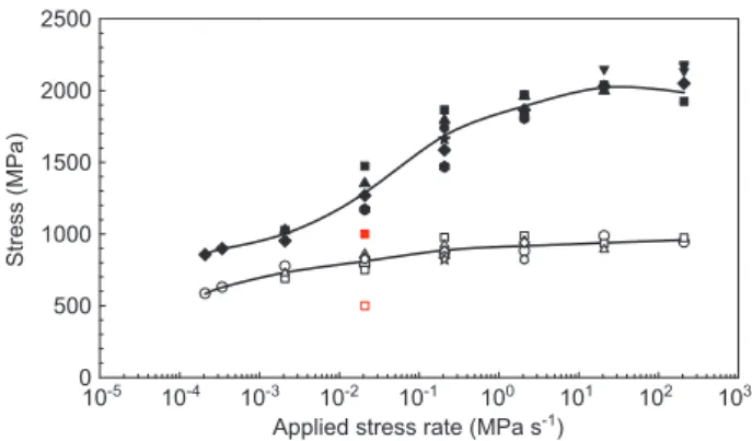
reduction in elongation) of the specimens in the environ-ment and an inert environenviron-ments, as stress corrosion fail-ures are associated with little macroscopic plastic deforma-tion during crack propagadeforma-tion; and (d) comparison of the fracture surfaces: intergranular SCC (IGSCC) or transgranu-lar SCC (TGSCC) associated with low ductilities in an envi-ronment, compared to dimple fracture surfaces associated with high ductility in an inert environment. For example, the measured fracture stress at various applied stress rates in an inert environment and in an aggressive environment is plotted as a function of the applied stress rate (Figure 6 ). At high applied stress rates, there is insufficient time for crack propagation, giving a fracture stress similar to that in an inert environment. At lower applied stress rates, stress corrosion cracks propagate, and the specimen fails at a stress lower than in an inert environment.
This type of test should not be confused with the con-stant-loading rate tests performed by Coleman, Weinstein, and Rostoker (1961), in which specimens (0.25-in., 5.0 mm, dia meter) were loaded at a rate of 200 lb/min (890 N/min) to some arbitrary maximum stress and immediately unloaded, removed from the test assembly, and examined for surface cracks at 20 × magnification. The stress at which the cracks were just resolvable was designated as the stress corrosion fracture stress, which is in fact the stress required to open the microcracks so that they were visible at 20 × and not the true fracture stress.
The LIST method offers the advantage that the strain rate on the specimen can be controlled through the applied stress rate. With the help of a potential drop technique, the threshold stress can be measured. Thus, this method combines the advantages of the constant-load tests and the constant-strain rate tests. Also, it is be quicker than either.
Inert environment
Aggressive environment
Low High
Applied stress rate (MPa s-1)
Fracture
stress
(MPa)
σSCC
Figure 6 Schematic diagram of the results from the LIST tests. There is SCC at intermediate and low applied stress rates. The threshold stress for SCC may level off at low applied stress rates.
This test was originally developed to study the SCC behavior of high-strength steel in water (Atrens et al., 1993; Ramamurthy & Atrens, 1993, 2010; Ramamur-thy, Lau, & Atrens, 2011). Since then, this test has been employed to study the SCC behavior of rock bolts (Gamboa & Atrens, 2003a,b, 2005; Villalba & Atrens, 2007, 2008b), commercial steels (Liu, Irwanto, & Atrens, 2013; Villa-lba & Atrens, 2008a), SCC and creep behavior of Aermet 100 (Oehlert & Atrens, 1998), copper alloys (Salmond & Atrens, 1992), magnesium (Atrens, Winzer, Song, Dietzel, & Blawert, 2006; Jia, Song, & Atrens, 2007; Winzer, Atrens, Dietzel, Song, et al., 2008; Winzer Atrens, Dietzel, Song, & Kainer, 2007), and X65 pipeline steel (Wang & Atrens, 1996, 2003b).
3 SCC mechanisms
3.1 Introduction
If SCC involves electrochemical processes and is con-trolled by the electrochemical conditions at the crack tip (Turnbull, 1992, 1993), then it is important to understand the electrochemical potential, pH, ion concentrations, and reactions occurring at the crack tip. For low-alloy steels in water, it is difficult to define the conditions at the crack tip because of the high resistivity of water. However, at the free corrosion potential, the rate of the anodic reac-tion equals the rate of the cathodic reacreac-tion. The electro-chemical reactions most likely to occur at the crack tip in low-alloy steels in water are:
Anode M → M n + + n e - (1) Cathode O 2 + 2H 2 O + 4e - → 4OH - (2) 2H + + 2e - → H 2 (3)
Which of the two cathodic reactions occurs depends on the local electrochemical conditions at the crack tip, such as potential, solution pH, and supply of oxygen, and may be critical in determining which of the two mechanisms of SCC (HE or AD) is operable.
3.2 Anodic dissolution (AD)
In the AD mechanism of SCC, the crack advance is due to the AD reaction at the crack tip. The crack sides are
assumed to be covered with a passive film, which inhibits corrosion and maintains the high aspect ratio necessary for a stress corrosion crack (Parkins, 1974; Vermilyea & Diegle, 1976). For SCC by AD, corrosion at the crack tip is a necessary but not a sufficient condition. The likelihood of corrosion in the crack can be assessed by referring to a Pourbaix diagram if the crack tip conditions are known. This also allows assessment of the possibility of passive film formation. In practice, it is difficult to determine the pH and potential at the crack tip. The crack velocity produced by an AD mechanism is directly related to the rate of metal dissolution at the crack tip (Dix, 1940). This suggests the possibility of comparing crack growth rates with the rate of metal dissolution as measured on film-free surfaces. This comparison presents some difficulties, however. Quenched and tempered steels in water tend to crack along grain boundaries (GBs) where segregation of impurities may alter the metal composition, so dissolution rates from metal of bulk composition may not be appli-cable. There is also, in the case of SCC, the possibility of strain-assisted dissolution, a factor again not present in dissolution of a smooth surface.
The slip dissolution model was proposed as a refine-ment to the AD model (Hoar & West, 1962; Newman, 1981; Scully, 1972a,b; Staehle, 1972; Vermilyea, 1972). In this model, the passive film forms over the crack sides and the crack tip. This results in the crack growth being stopped until the buildup of the crack tip strain is sufficient to rupture the crack tip passive film. The crack tip advances intermittently when the crack tip is exposed to the test solution. The crack velocity is influenced by the extent of crack growth at each step as well as the interval between two rupture events.
Some details of the processes are open to question. For example, the passive film may be fractured in a brittle manner, leaving the metal surface completely bare, or the film may be ductile, so that it is simply thinned by the strain (Diegle & Vermilyea, 1976; Vermilyea & Diegle, 1976). In order to overcome this drawback, Diegle and Ver-milyea (1976) and VerVer-milyea and Diegle (1976) assumed that no plastic deformation occurs during the dissolu-tion process, but that creep processes, after the AD, control the plastic deformation. Hall (2008, 2009) noted the similarities between the slip dissolution model and high-temperature creep crack growth and also proposed a revised model incorporating the role of creep in the slip dissolution model. His model also takes into account the rate of loading on the film rupture/dissolution/repassiva-tion cycle occurring at the crack tip. Another complica-tion arising from the slip dissolucomplica-tion model is the pos-sibility that, when the passive film ruptures in a brittle
manner, the crack may propagate in a brittle manner for some distance into the (otherwise ductile) metal ahead of the crack (Sieradzki & Newman, 1986). Sieradzki and Newman (1986) also suggested that the large depth of cor-rosion at each film rupture cycle, influenced by the plastic strain distribution ahead of the crack, would exceed the mechanical crack tip opening and would be inconsistent with the observed crack geometry and relatively little cor-rosion observed on the fracture surface. They concluded that the slip dissolution model aided by intergranular cor-rosion could explain IGSCC, but ruled out this model for the TGSCC.
3.3 Hydrogen embrittlement (HE)
Subcritical cracking of steels in H 2 /H 2 S atmospheres is the basis for the HE mechanisms (Nelson & Williams, 1977; Simmons, Pao, & Wei, 1978; Thompson, & Bernstein, 1981). Hydrogen may cause embrittlement as a result of hydrogen being present within the alloy during loading (internal HE) or the alloy under load exposed to a hydro-gen-containing environment (external HE) (Eliaz et al., 2002). This results in reduced ductility, reduced strength, and nonductile fracture.
For HE to occur, there must be a source of hydrogen, the hydrogen must be transported to the location where embrittlement occurs by some transportation processes, and a mechanism needs to cause embrittlement at the failure location. In water and other aqueous solutions, with the absence of external hydrogen, the source of hydrogen for HE is the cathodic reaction, and the occur-rence of this reaction is a necessary condition for any HE mechanism of SCC. If the crack tip electrochemical con-ditions are known, the likelihood of reaction 3 can be assessed by reference to the respective Pourbaix diagram. For HE to occur, the hydrogen concentrations need not be close to the solid solubility limit. Even low concentrations of hydrogen can cause HE. The concentration required for HE is also influenced by the yield strength; steel sus-ceptibility increases with increasing yield strength. For example, a few parts per million of hydrogen was found to cause HE in high-chromium martensitic steels over a large temperature range (-130 ° C to 250 ° C) (Beghini, Benamati, & Bertini, 1996). Steel composition is also known to influ-ence HE by modifying hydrogen absorption characteris-tics (Buckley, Placzankis, Lowder, Brown, & Brown, 1991; Jung, 1996; Liou, Shieh, Wei, & Wang, 1993; Rieck, 1985; Rieck et al., 1988). For example, alloying elements and impurities can influence the corrosion potential of the steel, thereby changing the interaction of the steel with
hydrogen, can act as traps for hydrogen, can poison the GBs, and can form passive films and protective surface layers.
Transportation of hydrogen to the degradation site is an important step in the HE process. Diffusion of hydro-gen, the incubation period, and the hydrogen concentra-tion buildup are important features that reflect the trans-portation kinetics (Birnbaum, 1994; Birnbaum & Sofronis, 1994). Introduction of the hydrogen atom (from solution in the case of SCC in water) into the lattice results in loca-lized volume (Peisl, 1978) and modulus changes (Mazzolai & Birnbaum, 1985; Mazzolai & Lewis, 1985). As a result, there is diffusion through normal interstitial lattice sites (NILSs) toward these regions to eliminate the chemical potential gradient. Hydrogen transported through NILS diffusion can accumulate at various microstructural heterogeneities, such as dislocations, GBs, inclusions, voids, and impurity atoms (Gibala & DeMiglio, 1981; Wert, 1983). Trapping has been observed to be an important part of HE, and its significance lies in the embrittling mecha-nism (Gibala & DeMiglio, 1981; Stevens & Bernstein, 1985). From the experimental data on annealed iron, Oriani and Josephic (1980) concluded that interfaces and micro-cracks were involved in trapping hydrogen. On the basis of the data from iron, Kumnick and Johnson (1974) esti-mated a trap density of 2.77 × 10 22 traps/m 2 and concluded
that this trap density is not likely to be associated with the long-range elastic-stress fields of dislocations. On the basis of later work (Johnson & Lin, 1981), they concluded that the trap binding energy is independent of tempera-ture and the amount of plastic deformation, and that the traps could be associated with imperfections, point defects, and dislocation debris. Hirth (1980) observed that that the trap binding energy reported by Kumnick and Johnson (1980) could correspond to the trap sites of standard mixed or screw dislocation cores.
Hydrogen transport by dislocations toward the crack tip may also be important (Tien, Nair, & Jensen, 1981). However, more dislocations also move away from the crack tip, thus cancelling the effect of hydrogen trans-port through dislocations. Moreover, other experimental evidence does not support hydrogen transport by dislo-cations (Frankel & Latanision, 1986; Ladna & Birnbaum, 1987).
Several possible mechanisms have been proposed for the embrittlement of metals by trapped hydrogen. These include (1) high gas pressure in internal voids (Zapffe & Sims, 1940), (2) hydrogen-enhanced localized plasticity (HELP) (Beachem, 1972; Birnbaum, 1994; Lynch, 1979), (3) hydrogen enhanced decohesion (HEDE) at or ahead of the crack tip (Oriani, 1970, 1978; Oriani & Josephic, 1977;
Troiano, 1960), (4) reduction in surface energy by adsorp-tion (Petch, 1956), and (5) formaadsorp-tion of a brittle hydride and cleavage fracture (Grossbeck & Birnbaum, 1977; Lufrano, Sofronis, & Birnbaum, 1998; Westlake, 1969). Of these, HELP and HEDE appear to be viable for the SCC of high-strength steels. Formation of hydrides and the asso-ciated brittle fracture has been shown to be applicable to systems where hydrides are stable or can be stabilized by an applied stress field, such as Ti (Frandsen, Paton, & Marcus, 1973; Shih, Robertson, & Birnbaum, 1988) and Zr (Dutton, Nuttall, Puls, & Simpson, 1977). Thermodynamic calculations (Flanagan & Mason, 1981) and microscopy observations (Takano & Suzuki, 1974) tend to support the presence of hydrides causing cracking in these materials. Where conditions are not suitable for the formation and the stability of hydrides, the HELP and HEDE mechanisms have been proposed for the embrittlement process. The HELP mechanism is based on the experimental observa-tions that over a range of temperatures and strain rates, the presence of hydrogen in a solid solution decreases the barriers to the dislocation motion. This results in an increased amount of deformation in a localized region adjacent to the fracture surface (Lynch, 2003: Robertson & Birnbaum, 1986; Rozenak, 1990). Thus, the fracture process is a highly localized plastic failure, even though the fracture is macroscopically brittle. Microscopic obser-vations support the onset of localized plasticity and the reduced macroscopic ductility. The other viable embrit-tlement process is HEDE, in which the atomic bonding is weakened by the presence of hydrogen in the solid solution (Gerberich, Chen, & St. John, 1975; Oriani, 1970, 1978; Oriani & Josephic, 1977; Troiano, 1960). There is support for this mechanism from systems in which signifi-cant hydride formation does not occur, and there is also absence of significant plastic deformation in the system. Further support has been provided by a thermodynamic argument (Hirth, 1980a,b; Hirth & Rice, 1980) and chemi-cal potential chemi-calculations (Daw & Baskes, 1984).
3.4 Surface mobility
Bianchi and Galvele (1987) and Galvele (1986, 1993) pro-posed the surface mobility mechanism to address some of the deficiencies in the AD and HE mechanisms. While proposing this mechanism, Galvele takes into considera-tion three aspects of stress corrosion cracks, namely, (1) the crack aspect ratio, the ratio between the crack length and crack opening can be well above 100, and in some cases even above 1000. This means that when the crack is propagating, the sides of the crack are expected to show
neither corrosion nor plastic deformation; (2) walls of the crack show no stress, whereas a high-stress concen-tration is found at the crack tip (thus, the environment is in contact with a strongly heterogeneous material over a short distance), and (3) the tensile stresses at the crack tip. In ductile materials, the stress at the crack tip increases up to the yield point, leading to a plastic zone in front of the crack. The size of the plastic zone is a function of the applied stress and the geometry of the sample.
The surface mobility mechanism postulates that SCC occurs at a temperature below 0.5 T m , where T m is the abso-lute melting point of the material. This enables volume diffusion to be ignored. It is postulated that only elastic tensile stresses are relevant to this mechanism. Signifi-cant stresses exist at the crack tip, and a tensile stress is known to reduce the free-energy formation of vacancies (Hirth & Nix, 1985). The surface mobility mechanism assumes that because of the action of the environment, only the first atomic layers of the metal are susceptible to measureable movement. Crack propagates an atomic dis-tance every time the stressed lattice at the tip of the crack captures a vacancy. This results in a surface depletion of vacancies. The rate-controlling process is the diffusion of the vacancies along the surface.
Galvele and coworkers have shown a correlation between the predictions from this mechanism and SCC in various systems, such as embrittlement of high-purity copper in CuCl at 200 ° C (Bianchi & Galvele, 1987), SCC of Ag-Pd and Ag-Au alloys (Duffo & Galvele, 1988, 1990), SCC of silver alloys in bromine vapor (Bianchi & Galvele, 1994), SCC of zirconium alloys and other close packed metals and alloys (Farina & Duffo, 2004; Farina, Duffo, & Galvele, 2003; Farina, Duff ó , & Galvele, 2005a), nuclear materials (Galvele, 1996), and SCC of Ag-Cd alloys in halide solu-tions (Duffo & Galvele, 1990).
Despite the correlations from the predictions of this mechanism, there have been some criticisms. Sieradzki and Friedersdorf (1994) observed that in one of the mani-festations of this mechanism the effect of the environment is to react with the metal to produce a low-melting-point compound. They contend that the surface of a crack is a free surface, i.e., no normal stresses act on them, and that the analysis employed by Galvele for the equilib-rium vacancy concentration was inappropriate. They also contend that Galvele neglected the effect of capillary process. Based on their analysis, they conclude that SCC crack propagation via surface mobility can be applicable in cases where there is a low crack-propagation rate, but that other models of cracking (AD, film-induced cleavage, etc.) should be considered for intrinsically ductile face-centered cubic metals.
Galvele (1994), in his reply, indicated that cracks can grow under compressive stress in certain alloy-environ-ment systems and that the formation of corrosion prod-ucts (oxides and other compounds) as a result of the inter-action between the metal and the environment would overcome any possible effect of surface tension. He has also pointed out the alloy-environment systems where SCC can be explained by the surface mobility mechanism as a validation of his postulations.
The validity of the surface mobility mechanism was also raised by Gutman (2003). The comments made in his paper were addressed by Galvele (2003). Galvele also states that the surface mobility mechanism is applicable to only a limited number of alloy-environment systems. Additional support was provided by Vogt and Speidel (1998).
4 Strain and strain rate
4.1 Role of crack tip strain rate in SCC
For the SCC of high-strength steels in aqueous solutions, both AD and HE models require the rupture of passive films for the subsequent crack advance. For the AD model, Scully (1967, 1972a,b, 1980) proposed that (i) crack propagation would stop if the crack tip strain rate falls below the repassivation rate, and (ii) a crack tip strain rate greater than the repassivation rate leads to some other form of corrosion and not stress corrosion crack propagation. In his model, crack propagation occurs only when the crack tip strain rate is equal to the repas-sivation rate. Diegle and Vermilyea (1976) and Vermilyea (1972, 1976) proposed a variation of this model, in which corrosion occurs when the crack tip was bare, and this is followed by the repassivation of the crack tip. Because of the removal of some material near the crack tip from the previous corrosion process, the material just ahead of the crack tip experiences a strain transient. When the accu-mulated strain transient ( “ creep strain ” ) reaches the criti-cal strain required to rupture the passive film, corrosion occurs at the crack tip, resulting in crack advancement. Crack advance occurs by a cycle of film rupture and repas-sivation. The critical strain rate controls the frequency of film rupture events and controls the stress corrosion crack growth rate. Thus, it was proposed that the thresh-old intensity of SCC, K ISCC , corresponds to the value of the critical crack tip strain rate (Scully, 1975). Moreover, because of the time dependency of the film rupture/repas-sivation events, this process is analogous to creep despite
occurring at relatively low temperatures (Vermilyea, 1972). The relationship between the repassivation rate and the film rupture rate has been schematically described by Newman (1981) in Figure 7 . The threshold stress inten-sity factor ( K ISCC ) is defined as the stress intensity factor below which crack growth effectively ceases. Newman has shown that decreasing K increases the degree of passiva-tion between film rupture events, and at a value below K ISCC this leads to crack arrest. Thus, K ISCC may also be defined by the combination of crack tip strain rate and repassiva-tion rate, and this definirepassiva-tion is similar to that employed by Scully (1978, 1980).
The crack tip strain rate has also a significant role in the HE mechanism. Its first role is the generation of hydrogen during the film rupture process. Thus, the fre-quency of film rupture and the subsequent repassiva-tion process influences the generarepassiva-tion of hydrogen at the crack tip and its entry into the region ahead of the crack tip. De Moraes, Bastian, and Ponciano (2005) have shown that plastic straining of pipeline steels in low H 2 S environment increased the uptake of hydrogen. They considered that this could be due to the effect of hydro-gen trapping and transport promoted by moving dislo-cations. This is also supported by observations of Tien, Thompson, Bernstein, and Richards (1976), according to whom the transport of hydrogen promoted by moving dislocations can be four orders of magnitude higher than the hydrogen flux due to ordinary diffusion. Further support was provided in the review of Louthan, McNitt, and Sisson (1981), who showed that plastic deformation
Normal passivation curve
Depth of metal lost (L)
tc Lc
V –
Time (t)
Figure 7 Schematic diagram illustrating how the mean crack velocity is influenced by the metal loss as a function of time. Reprinted from Newman (1981) with permission from Elsevier.
during exposure to hydrogen increased the apparent hydrogen diffusivity.
Tien et al. (1976) also proposed a kinetic model of hydrogen transport involving large supersaturations of hydrogen at voids and interfaces in the metal. However, Johnson and Hirth (1976) have since shown that such supersaturations are not possible in steels owing to the high diffusivity of hydrogen in the body-centered cubic
α iron lattice. Transport of hydrogen by dislocations has also been proposed by Lynch (1979, 2007) and Oriani (1978). Lynch (2007) also proposed that the strain rate may influence HE mechanisms of SCC through enhanced trans-port of hydrogen as Cottrell atmospheres around mobile dislocations. However, contradicting evidence has been presented by Zakroczymski and Szklarska-Smialowska (1985), who found that the dislocation motion associ-ated with plastic strain does not enhance the transport of hydrogen in iron.
The previous discussions indicate that the crack tip strain rate can act as a rate-limiting step in the kine-tics of SCC. For example, in the AD model, the crack tip strain rate controls the film rupture events, thus control-ling the metal dissolution rate. In the HE model, the crack tip strain rate controls the hydrogen production in some systems and its transport to locations ahead of the crack tip. For the embrittlement models involving localized plasticity, crack tip strain rate also enhanced localized plasticity through increased hydrogen productions and/or transport. Because the production of hydrogen is through the corrosion at the crack tip in aqueous solutions, the investigations into the effect of crack tip strain rate may not reveal the mechanism of SCC but may help identify the processes important in defining K ISCC , the threshold stress ( σ SCC ), and the rate-limiting step.
4.2 Experimental observations on strain rate
For the tests involving smooth specimens, the crack tip strain rate is normally controlled by the externally applied extension rate (CERT) or by the strain rate (SSRT), applied stress rate (LIST) or by the applied stress or stress intensity factor (constant-load type tests). These tests, in addition to those using precracked specimens, have been used to study the effect of crack tip strain rate on the SCC kinetics. Maeng, Lee, and Kim (2005) employed CERT tests to study the effect of strain rate for the SCC testing of 3.5NiCrMoV steels (675 MPa yield strength) in high-tem-perature (50 – 200 ° C) water. They have shown that the elon-gation increased linearly with the logarithmic increase in the strain rate. Fracture surface morphology indicated
little deformation at low strain rates and extensive defor-mation at high strain rates, consistent with the observa-tions from elongation measurements. They explained their results based on the AD mechanism: At intermedi-ate strain rintermedi-ates the metal dissolution rintermedi-ate increased with decreasing strain rate due to greater time available for the crack tip to be present in the active condition. At higher strain rates, there was not time for sufficient metal disso-lution for crack advancement and hence ductile fracture was observed in their study. At low strain rates, they con-sidered the plastic deformation to be too low to cause film rupture and metal dissolution.
Maiya (1987) and Maiya and Shack (1984) also employed CERT tests to study the influence of crack tip strain rate on SCC of stainless steels in water. They also developed a model for crack growth based on the slip dis-solution model from Ford (1982, 1984). Their data indi-cated that the time to failure decreased with increased strain rate for both IGSCC and TGSCC modes of failure. In converse, the crack growth rates increased with increas-ing applied strain rates for the measurements in a sulfate environment. The average crack tip strain rates, calculated from their model, were also found to result in increasing crack growth rates, similar to the trends observed for the applied strain rate.
Wang and Atrens (1996) also demonstrated the influ-ence of crack tip strain rate by conducting LIST tests on a low-strength X65C pipeline steel in 1 N Na 2 CO 3 + 1 N NaHCO 3 solution at 70 ° C. In their study, the applied strain rate was controlled by varying the applied stress rate. They found that the crack initiation stress decreased with decreasing applied stress rate. Their results were also attributed to the AD mechanism in which there is a competition between the film rupture rate (through the buildup of crack tip strain) and the repassivation rate. At higher strain rates, ductile fracture was observed due to insufficient time for corrosion processes, and the repassivation rate was criti-cal at lower applied stress rates. Their results were found to be in the latter regime.
One of the more definitive experiments on the influ-ence of crack tip strain rate was performed by Parkins (1979a, 1990) on a low-strength C-Mn pipeline steel loaded as cantilevers while exposed to the carbonate-bicarbonate solution at 75 ° C that causes IGSCC at the potential range of -600 to -700 mV sce . In the experimental setup, measure-ment of the deflection of the beam as a function of time represented the crack tip opening displacement as a func-tion of time, i.e., the creep and cracking response. The data are shown in Figure 8 . When the potential was in the cracking range, the beam deflection response was as shown in curve A. The initial part of the curve represents
the creep in the plastic zone. Stress corrosion crack ini-tiation and growth resulted in an increase in stress and further creep so that the beam deflection began to acce-lerate under the joint action of stress and the creep at the crack tip. In contrast, if the sample was held under the same stress intensity factor, however, at a potential where SCC did not occur, the beam deflection behavior repre-sented the simple creep influence and was not compli-cated by the crack initiation and propagation effects. This was represented by the curve B in Figure 8. Thus, a differ-ence between the two curves represented the SCC behavior of this steel in this solution. In addition to these two meas-urements, Parkins performed additional experiments in which the potential was held outside the SCC range (-950 mV sce ) for a while before switching to the susceptible potential range (-650 mV sce ) and vice versa. The response from these measurements is shown in curves C and D. Curve C represented the case where the potential was held outside the range for 40 h and then switched over to the susceptible range. This curve was similar to the curve B and indicated that SCC did not occur on this sample. This was despite the fact that the stress intensity factor was the same as that for the experiment shown by curve A. Parkins explained this by arguing that by the time the potential was switched over to the susceptible range, the creep rate had diminished to a value below which it could not initiate or sustain cracking. He tested this hypothesis by conducting another experiment in which the potential was at the nonsusceptible region when the experiment
2.0 1.5 Beam deflection (mm) 1.0 0 0 20 40 60 80 Time (h) B C D A
Figure 8 Beam deflection-time curves for constant-load cantilever beam tests on a pipeline steel in 1 N Na 2 CO 3 + 1 N NaHCO 3 at 75 ° C
and the effects of cracking (-0.65V sce ) and noncracking (-0.9 V sce ) potentials. Reprinted from Parkins (1979, 1990) with permission from NACE.
started and switched over to the susceptible range before the creep rate had fallen to a low value, shown in curve C. Curve D represented the case in which the beam deflec-tion behavior was similar to curve A, i.e., as if the poten-tial switch did not matter. These results indicated that the controlling factor in the stress corrosion experiments was not the initial stress or stress intensity factor, but the creep or the strain rate at the crack tip.
Rieck and coworkers (Rieck, 1985; Rieck et al., 1988; Rieck, Atrens, & Smith, 1989) performed similar tests on quenched and tempered low-alloy high-strength steels, using precracked fracture mechanics specimens. Their results are shown in Table 1 . Specimen 1 exhibited SCC, with the region II crack velocity equal to 1.14 × 10 -7 m s -1 .
In contrast, the second specimen was allowed to creep for 72 h before hot water was added, and this specimen did not exhibit cracking. Moreover, unlike Parkins, Rieck et al. did not find a minimum time of prior creep required to prevent SCC, even though the creep time was as low as 10 min in one case. They postulated that the primary creep was exhausted more rapidly in the high-strength steels employed in their study compared to the low-strength steels studied by Parkins.
In further tests, Rieck and coworkers demonstrated that it was possible to arrest a growing crack by remov-ing the water from the cell while the specimens were still loaded and allowing creep to occur. Their results are pre-sented in Table 2 . Specimen 3 exhibited SCC when exposed to water, and the crack velocity was greater than that observed for 3.5NiCrMoV steel shown in Table 2. This is due to the greater yield strength of this material. However, when the specimen (specimen 5) was allowed to creep for 48 h in air (dried with P 2 O 5 ) subsequent addition of water did not cause SCC on this sample. These results were again consistent with the mechanism that once primary creep was exhausted, the critical crack tip strain rate was not reached and SCC did not proceed.
Rieck and coworkers also investigated the possibility of restarting SCC once it had been arrested by creep. They found that an increase in the applied stress intensity from 20 to 65 MPa √m was required to restart cracking. These results for subcritical cracking in aqueous solutions are to be compared with behavior in pure gaseous hydrogen, where the cracking is not expected to be dependent on the crack tip strain, as hydrogen is always present and there is no passive film at the crack tip (provided the hydrogen is sufficiently pure and that the crack is started in the high-purity hydrogen atmosphere). Oriani and Josephic (1974) loaded specimens of AISI 4340 to a desired stress intensity factor and then increased the pressure of hydrogen until cracking began. The threshold stress intensity factor for cracking, K IH , was found to be independent of the time for which the specimen was loaded prior to introduction of the hydrogen, for holding times between 15 min and 16 h. The results of Rieck and coworkers (Rieck, 1985; Rieck et al., 1988), however, show that for such high-strength steels, primary creep is exhausted within 10 min, so no effect would be expected within this range of holding times. Oriani and Josephic (1974) did not test specimens where the hydrogen was introduced before loading, so it is not possible to determine from their results whether prior creep has any effect on K IH . The expectation that the crack tip strain is not necessary for cracking in hydrogen is partially supported by the results of Rieck and cowork-ers (Rieck, 1985; Rieck et al., 1988), who found that SCC, arrested by a period of creep, could be restarted by hydro-gen charging. Under conditions of hydrohydro-gen charging, a dissolution reaction within the crack is not required to maintain the hydrogen supply. Because the specimen was in water, there was a passive film to be contended with, and indeed in some cases it was found necessary to abrade the side of the specimen in order to allow entry of hydro-gen. In gaseous hydrogen, however, K IH is expected to be an equilibrium quantity, dependent only on the hydrogen
Table 1 Effect of prior creep on SCC, after Rieck et al. (1988, 1989).
Specimen Metal Creep time (h) Environment Cracking Comment
1 3.5NiCrMoV 0 H 2 O Yes V = 1.14×10⁻⁷ m s -1 at 25° C
2 3.5NiCrMoV 72 Silica gel-dried air No
Table 2 Effect of environment of creep inhibiting SCC, after Rieck et al. (1988, 1989).
Specimen Metal Creep time (h) Environment Cracking Comment
3 4340 0 H 2 O Yes V = 8×10⁻⁵ m s -1
pressure, P H2 . Further experiments, with hydrogen intro-duced prior to loading, are required in order to determine conclusively whether crack tip strain rate affects K IH .
Oehlert and Atrens (1994) investigated the room-temperature creep behavior of three high-strength steels. Parameters such as creep stress, loading rate, stress history, and heat treatment were altered, and their influ-ence on the low-temperature creep was reported. The primary creep in all three alloys agreed well with the loga-rithmic creep law, and the creep mechanism was identi-fied as pure dislocation creep. Higher stresses and high loading rates led to increased creep strains and strain rates. Reloading after a period of creep resulted in sig-nificantly decreased creep strains, and no recovery of the time-dependent deformation could be detected. The yield strength of the materials per se had no influence on the room-temperature creep, whereas the same material with decreased 0.2 % offset strength showed significantly reduced time-dependent deformation. The possible inter-action between primary creep and SCC was discussed.
Kinaev, Cousens, and Atrens (1999) studied the influ-ence of hydrogen and water vapor environments on the plastic behavior in the vicinity of the crack tip for AISI 4340. Hydrogen and water vapor (at a pressure of 15 torr) significantly increased the crack tip opening displace-ment. The crack tip strain distribution in 15 torr hydrogen was significantly different to that measured in vacuum. In the presence of sufficient hydrogen, the plastic zone was larger and was elongated in the direction of crack propagation; moreover, there was significant creep. These observations support the hydrogen-enhanced localized plasticity model for HE in this steel. The strain distribu-tion in the presence of water vapor also suggests that SCC in AISI 4340 occurs via the hydrogen-enhanced localized plasticity mechanism.
4.3 Influence of surface strain
Atrens and Wang (1998) studied the SCC initiation process for 4340 high-strength steel in distilled water at room temperature using an environmental scanning electron microscope. It was found that the applied stress acceler-ated oxide film formation, which has an important influ-ence on the subsequent SCC initiation. SCC was observed to initiate in the following circumstances: (1) cracking of a thick oxide film, leading to SCC initiation along metal GBs; (2) the initiation of pits initiating SCC in the metal; and (3) SCC initiating from the edge of the specimen.
All these three SCC initiation circumstances are con-sistent with the following model, which couples SCC
initiation with cracking of a surface protective oxide. There is a dynamic interaction between oxide formation, the applied stress, oxide cracking, pitting, and the initia-tion of SCC. An aspect of the dynamic interacinitia-tion is for-mation of cracks in a protective surface oxide because of the applied stress, exposure to the water bare metal at the oxide crack tip, and oxidation of the bare metal, causing crack healing. Oxide crack healing would be competing with the initiation of IGSCC if an oxide crack meets the metal surface at a GB. If the IGSCC penetration is suffi-ciently fast along the metal GB, then the crack yaws open, preventing healing of the oxide crack. If IGSCC penetra-tion is not sufficiently fast, then the oxidapenetra-tion process could produce sufficient oxide to fill both the stress corrosion crack and the oxide crack; in this case, there would be initiation of SCC but only limited propagation of SCC. Stress-induced cracks in thin oxide can induce pits, which initiate SCC, and under some conditions such stress-induced cracks in a thin oxide can directly initiate SCC.
4.4 Discussion on strain and strain rate
The above results, and in particular the observed influ-ence of prior creep on K ISCC , demonstrate that crack tip strain is critical in the SCC of high-strength steels in water. The role of crack tip strain for tests in aqueous solutions is best explained in terms of the fracture of surface films at the crack tip in order to allow a dissolution reaction to proceed. Then, K ISCC can be defined as the stress intensity factor required to produce a critical crack tip strain rate, which is required to continuously rupture the surface film. Some of the experimental data presented in the previ-ous section, such as that of Maeng Lee, and Kim (2005) and Wang and Atrens (1996), can be explained on the basis of the AD model. Moreover, Parkins has also shown that the AD model can be applicable to the SCC of low-strength pipeline steel (Parkins, Belhimer, & Blanchard, 1993). Some of the experimental results from the high-strength steels, especially that of Rieck (1985) and Rieck et al. (1988), are explicable in terms of both AD and HE models of SCC in water, as both models require a dissolu-tion reacdissolu-tion within the crack, and crack tip strain pro-vides the means whereby this dissolution reaction can be maintained. Thus, the mechanism of SCC cannot be distinguished from such studies. Moreover, the results are useful in that they can identify the rate-controlling step of SCC in this system and have also identified a major controlling process for the SCC of steels in water, one that defines K ISCC .
The film at the crack tip for 4340 may not be a passive film in the same sense as that for stainless steels. Its role, as postulated above, is to be at least partially protective (i.e., decrease the corrosion reaction) and to hinder hydro-gen entry into the metal.
5 Crack velocity
5.1 Introduction
Previous sections described the evidence that the crack tip strain rate was the controlling parameter of SCC of high-strength low-alloy steels in aqueous environments. The crack tip strain rate was shown to be the rate-limiting step of SCC in this system due to the dissolution of the passive film at the crack tip, thus enabling crack advance through metal dissolution (AD mechanism) or hydrogen genera-tion (HE mechanism). Thus, the threshold stress (σ SCC )
or the threshold stress intensity factor ( K ISCC ) is defined by the minimum crack tip strain rate required to sustain crack advance and to maintain the crack aspect ratio at the crack tip. Another parameter that defines the kine tics of SCC is the crack velocity v , which controls the rate of crack propagation and the time to failure in tests using tensile specimens, such as CERT, SSRT, and LIST. Determi-nation of crack velocity is simpler in fracture mechanics tests, which employ precracked specimens, thus elimi-nating the issues associated with crack initiation. Hence, these tests have been employed extensively to determine the effect of various parameters on the crack growth rate (crack velocity).
The threshold stress or the threshold stress intensity factor can also be defined as the value at which the lowest crack velocity can be measured in SCC tests. Depending on the experimental conditions, this value can be as high as 10 -8 m s -1 (Simmons et al., 1978) or as low as 10 -11 m s -1
(Speidel, 1984; Speidel & Magdowski, 1986). For SCC experi-ments in aqueous solutions, the rate-limiting step that con-trols the lowest crack velocity would be the critical crack tip strain rate that would be needed to maintain a balance between the rupture rate and the repassivation rate (Scully, 1967, 1980, 1972a,b), thus enabling the metal dissolution or hydrogen generation or vacancy generation at the crack tip depending on the mechanism of SCC.
As the stress/stress intensity factor is increased, the crack velocity increases until it reaches a plateau above which further increase in the stress intensity does not result in the increase in crack velocity. This is known as the plateau crack velocity, v II . The rate-limiting step
that controls the plateau crack velocity is dependent on the mechanism of cracking. For the AD mechanism, the maximum dissolution rate that is allowed at the bare crack tip controls the plateau crack velocity. For the HE mechanism, the rate of hydrogen transport to the crack tip is supposed to control the plateau crack velocity.
5.2 Experimental observations
SCC kinetics of high-strength steels are different in water and in gaseous hydrogen as shown by the results from Nelson and Williams (1977). Using double torsion speci-mens, they conducted experiments at various tempera-tures and using steels of different yield strengths. Figure 9 shows their data in water at different temperatures for 4130 of yield strength 1330 MPa. Their measurements indicated that the threshold stress intensity factor remained the same, independent of temperature. However, the plateau crack velocity increased by approximately four orders of magnitude when the temperature rose from 1 ° C to 89 ° C. In contrast, the corresponding results in gaseous hydrogen (Figure 10 ) indicated that the threshold stress intensity
K IH increased with increasing temperature. However, the plateau crack velocity increased with increasing tempera-ture up to 53 ° C and then decreased with further increase
10-3 T (°C) 1 12 24 39 53 62 72 89 10-4 10-5 10-6 10-7 10-8 0 10 20 30 40 50 60 K (MNm-3/2) (msec -1) da dt
Figure 9 Crack velocity vs. stress intensity factor for 4130 (1330 MPa) in distilled water at various temperatures. Reprinted from Nelson and Williams (1977) with permission from NACE.
in temperature. In addition, the extent of increase in the plateau crack velocity was not to the same extent as that in water experiments, suggesting that the activation ener-gies for the rate-limiting step were lower than those in water experiments. These results indicated that the crack growth kinetics were different in water and in gaseous hydrogen for the same steel.
Complementary data for the 4340 steel ( σ y = 1344 MPa)
were generated by Simmons et al. (1978), and their results are presented in Figure 11 (in water) and 2.1 bar (133 kPa gaseous hydrogen). These are the Arrhenius plots of the plateau crack velocity as a function of temperature. For the water experiments (Figure 11), the crack velocity increased with increasing temperature, similar to the results from Nelson and Williams (1977). In contrast, there was a maximum in the crack velocity in gaseous hydrogen (Figure 12 ). The maximum temperature appears to be slightly greater than that observed by Nelson and Williams. Finally, the activation energy was greater for the water experiments, again similar to the results from the previous study.
Experiments in water at different temperatures have also been conducted by Magdowski (1987a,b), Speidel and Bertilsson (1984), and Speidel and Magdowski (1986) using different low-alloy steels. Their results again
indicated that increases in temperature resulted in the increase in plateau crack velocity, whereas the threshold stress intensity factor remained unaffected. These obser-vations were similar to the results reported by Nelson and Williams (1977) and Simmons et al. (1978).
10-3 T (°C) -43 -11 24 53 75 87 102 130 10-4 10-5 10-6 10-7 10-8 0 10 20 30 40 50 60 K (MNm-3/2) (msec -1) da dt
Figure 10 Crack velocity vs. stress intensity factor for 4130 (1330 MPa) in 77.3 kPa gaseous hydrogen at various temperatures. Reprinted from Nelson and Williams (1977) with permission from NACE. AISI 4340 Steel in distilled water 90 pct and 95 pct confidence intervals 33.5±7.4 kJ/mol (@95pct) ±5.0 kJ/mol (@90pct) 103/T (°K-1) Stage II crack growth rate (m/s) Stage II crack growth rate (in/s) 3.0 10-4 80 60 40 20 0 Temperature (°C) 10-5 10-4 10-3 3.5
Figure 11 An Arrhenius plot of the plateau crack velocity as a function of temperature for 4340 in water at various temperatures. Reprinted from Simmons et al. (1978) with permission from Springer.
AISI 4340 Steel in 133 kPa hydrogen 90 pct and 95 pct confidence intervals -14.7±4.3 kJ/mol (@95pct) ±2.9 kJ/mol (@90pct) 140 100 80 60 40 20 0 Temperature (°C) Stage II crack growth rate (m/s) 10-4 10-3 10-5 Stage II crack growth rate (in/s) 10-3 10-2 103/T (°K-1) 3.0 3.5 4.0 2.5
Figure 12 An Arrhenius plot of the plateau crack velocity as a function of temperature for 4340 in 133 kPa hydrogen at various temperatures. Reprinted from Simmons et al. (1978) with permission from Springer.
The effect of yield strength on the crack velocity was also investigated by Magdowski (1987a,b), Speidel and Bertilsson (1984), and Speidel and Magdowski (1986) using a number of low-alloy steels that had been quenched and tempered. Their results, shown in Figures 13 and 14, indicated that the steel composition did not influence the plateau stress corrosion crack velocity and that the plateau crack velocity was controlled by the yield strength. Note that Figure 14 is similar to Figure 1 and also shows the influence of temperature.
The effect of temperature was further investigated by Magdowski (1987a,b), and the results are shown in Figure 15 . SCC occurred in two different temperature regimes, each with a specific activation energy. This suggested that the rate-limiting processes and the mechanism of cracking could be different in the two temperature regimes. Galvale (1990) has compared the data from Magdowski with the surface-mobility stress-corrosion-cracking mechanism predictions and observed a good correlation between the predicted and the measured values.
Figure 16 shows the influence of yield strength on the kinetics of SCC in the low-temperature regime (at 23 ° C). Here, v II increased with the strength of the metal, as is usual for the higher temperatures. K ISCC , instead of being independent of strength, decreased from 49 MPa m ½
at 1025 MPa to 17 MPa m ½ at 1490 MPa. This behavior
was similar to that observed by workers such as Chu, Liu, Hsiao, and Li (1981), who worked with high-strength steels at room temperature, but contrary to behavior in the high-temperature regime. Such behavior is similar to the observed behavior in gaseous hydrogen, tending to suggest an HE mechanism of SCC in the low-temperature regime.
Rieck (1985) tested two quenched and tempered low-alloy steels in water at 90 ° C. This is in the high-temperature region of cracking as defined by Figure 15. For conventional heat treatment schedules, producing a range of strengths from 560 to 1700 MPa, the plateau crack velocity, v II , displayed the well-established correla-tion with strength initially noted by Speidel and Bertils-son (1984), and the results were within the error band of Figure 1. For these conventional heat treatments, austeni-tizing temperature and prior austenite grain size had no effect on v II . An intercritical heat treatment, however, pro-duced the same crack velocity as the fully austenitized and quenched steel, despite the lower strength and hardness. On the basis of fractography, this behavior was explained in terms of a slight change in the cracking mechanism, with ferrite breaking in a ductile manner, whereas the martensite suffered IGSCC.
Stress corrosion crack velocity , ∆ a/ ∆ t (m/s) 10-5 10-6 10-7 10-8 10-9 10-10 10-11 10-12 0 20 40 60 80 100 120 Steel 26 NiCrMoV 12 7 (A 471) σy=760 MPa Steel 26 NiCrMoV 12 7 (A 471) σy=1220 MPa Intergranular SCC in H2O, 100°C, deaerated Steel 41 SiNiCrMoV 77 (4340M) σy=1700 MPa
Stress intensity, K (MPa·√m) KISCC
Figure 13 The effect of yield strength on the stress corrosion crack velocity for two different steels in water at 100 ° C. Reprinted from Speidel (1984) and Speidel and Bertilsson (1984) with permission from Springer.
Stress corrosion cracking in hot water 10-4
10-5 10-6 10-7 10-8
Stress corrosion crack growth
∆ a/ ∆ t, (m/s) 10-9 10-10 10-11 10-12 0 200 400 600 800 1000 1200 1400 1600 Yield strength, Rp0.2, (MPa)
reaction pressure vessel steel, 20MnMoNi55, A533B Steam turbine rotor steel NiCrMoV, CrNiMo Cast steel GS 40 Low alloy steel, A508-2, A33-6
100°C 160°C 288°C
Figure 14 The effect of yield strength and temperature on the crack velocity for low-alloy steels in water. Reprinted from Magdowski (1987) with permission from the Swiss Academy of Science.