2011
1±-i:
-
V '( ! ) '
i
t—
I-
MI-6 ff5E
Research on Skid Control of Small Electric Vehicle with
Hydraulic-Mechanical Hybrid Brake System
MW NJ
?f
ADVISOR ASSOCIATE PROF. DR HIROHIKO OGINO
V
4Z&Jc' v t J° — -(
Mohamad Heerwan Bin Peeie
PERPIJSTAKAAN t UNIVERSITI MALAYSIA PAHANG
-P hnp No. Panggilan TL Tarikh
Table of Contents
1. Introduction 2
2. Objective 4
3. Antilock Brake System (ABS) 5
3.1 Composition of ABS 5
3.2 Operation of ABS 8
4. Simulation 11
4.1 Main Symbols 11
4.2 Vehicle Model 14
4.2.1 Vehicle Ride Model 14
4.2.2 Suspension System 15
4.3 Braking System 22
4.3.1 Hydraulic-Mechanical Brake System 22
4.4 Simulation Model 24
4.5 Regenerative Brake
4.6 Calculation Condition 26
4.7 Basic equation of Vehicle Movement 27
5. Result and Discussion 40
6. Conclusion 50
7. References 51
8. Attachment 53
1. Introduction
In recent years, environmental problems have spread around the world. To cope with this problem, electric vehicle have widely used. As we.know, the fundamental of a driving method for electric vehicle can be separate into two types, which are one motor system and in-wheel motor system. There are many advantages by using in wheel motors such as motors torque generation is faster and accurate, motors can be installed in 2 or 4 wheels, and motors torque can be known precisely. For a small electric vehicle, in-wheel motor is more suitable than one motor.
Although small electric vehicle have a great in-wheel motor, the safety equipment of small electric vehicle is not sufficient because it only contains seat belts as safety equipment. The hydraulic unit of Antilock Brake System (ABS) cannot install into small electric vehicle because there is no space. Therefore, small electric vehicles employ a mechanical brake system rather than a hydraulic brake system. The demerit of the mechanical brake system is the stiffness of the system is smaller than the hydraulic brake system and the response performance of the braking force also low. As such, small electric vehicles may be considered to provide insufficient safety.
In fact, on slippery surfaces, even professional drivers can't stop as quickly without ABS as an average driver can with ABS. So, it is important to install ABS into small electric vehicle. ABS can prevent wheels from locking up and provide the shortest stopping distance on slippery surfaces. The Insurance Institute for Highway Safety (IllS) has conducted several studies trying to determine if cars equipped with ABS are involved in more or fewer fatal accidents. It turns out that in a 1996 study, vehicles equipped with ABS were overall no less likely to be involved in fatal accidents than vehicles without ABS.
2. Objective
The purpose of the present study is to improve the safety and
stability systems of small electric vehicle. In this research, we
introduce the simulation model of hydraulic-mechanical hybrid brake
system with Antilock Brake System (ABS). The main focus of this
research is to investigate the effect of the ABS operational with control
of regenerative brake on turning motion. The vehicle motion during
braking in a small electric vehicle was simulated for an ABS combined
with a hydraulic-mechanical hybrid brake system. By using the equation
of motion along the longitudinal and lateral axis, the yawing moment
equation of motion, and the rolling moment equation of motion, the
pedal
3. Antilock Brake System (ABS)
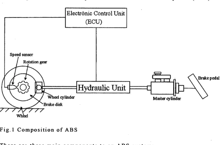
3.1 Composition of ABS
Fig. 1 shows the composition of Antilock Brake System (ABS).
Fig. I Composition of ABS
There are three main components to an ABS system: 1. Speed sensors
The speed sensors are located at each rear tire and it can provide information either the wheel is lock or not. This sensor produces an AC voltage signal that varies in frequency according to the output of rotation gear speed.
2. Hydraulic Unit
Right before wheel locks up, it will experience a rapid
deceleration. If left unchecked, the wheel would stop much more
quickly than any car could. It might take a car five seconds to stop
from 90 km/h under ideal conditions, but a wheel that locks up
could not stop spinning in less than a second.
The ECU knows that such a rapid deceleration is impossible,
so it reduces the pressure to that brake until it sees acceleration,
then it increase the pressure until it sees the deceleration again. It
can do this quickly before the tire can actually significantly
change speed. The result is that the tire slows down at the same
rate as the car, with the brakes keeping the tires very near the
point at which they will start to lock up. This gives the system
maximum braking power.
3.2 Operational of ABS
The braking model depends on the decrease of kinetic energy.
When the driver applies the brake in order to slow the vehicle, the speed
of the wheels become slightly slower than the speed of the body, which
is traveling along under its own inertia. This difference in speed is
called slip ratio. Here we define the slip ratio as the following
equation:
V — rco
xlOO [%]
where u denotes the vehicle speed, and Ro is the wheel speed. R and co are the radius of the tire and the rotational speed of the tire. This ratio can vary from 0 (perfect match between wheel and vehicle speeds) to the 1 (the wheel is locked), and it is shown that the wheel is both rolling and sliding.
Typical tire characteristics during braking are shown in Fig.3. It can be seen that the side force and the friction coefficient are depend on the slip ratio. In a driving condition (A. 0) , friction coefficient is 0 and cornering force will having a maximum value. When a driver steps on the brake pedal, the slip ratio is increase and the cornering force will decrease, and tire lock will occur if 2 100. In this situation, cornering force is almost 0 and the braking force will lost. From this graph, at a maximum value of friction coefficient (pmax), we plot the optimum value of slip ratio (A 0 ). According to the braking pressure, the stable region of slip ratio is between 0 to )opt. If the slip ratio is over Aop t , the tire was easy to lock.
The ABS is designed to control the wheel slip ratio in stable region so that a maximum friction coefficient is obtained and a suitable side force is maintained. It is important to maintain the side force because it guarantees the vehicle stability. In order to ensure the system do not move under the unstable region of operation, the ABS will control the operation of IN valve and OUT vale. When tire lock occurs, i.e., when the slip ratio become 100%, the IN valve is closed, the OUT valve is opened, and the pumps begin to operate. The pressure in the wheel cylinder and the braking force are decreased. As a result, the slip ratio become small, and the friction coefficient and the side force become large. When the slip ratio become too small, the IN valve open and the OUT valve close again. The pressure in the wheel cylinder and
P max 4. V 0 C.) 0 C.) V C.) 0 IL4 00 V 4-. 0 0
the braking force are increased, and the slip ratio then becomes large. This mechanism will repeatedly until the vehicle totally stop.
0 A.P Slip Ratio ) 100
4. Simulation
The main symbols in basic equations and programming was shown in Table.!.
4.1 Main Symbol
Table.! Variable in Basic Equations and Programming
Symb Physical Meaning Variable in Unit Inertial
ol programming Value
Af Area of front wheel areaF m2 2.83x10³
cylinder
Ar Area of rear wheel areaR m2 7.07x10⁴
cylinder
df Diameter of front wheel diaF m2 0.06
cylinder
dr Diameter of rear wheel diaR m2 0.03
cylinder
hf The front roll center - - -
height from the ground
h1. The rear roll center - - -
height from the ground
h5 Distance between the heightS m 0.105
vehicle center of gravity and the roll axis
I Yaw inertia moment of YAWINERTIA k9m2 1470
a gravity point
I Yaw inertia moment of inertiaZZS kgm2 100.0
upper side of spring
l Yaw inertia moment of inertiaZZU kgm2 1370.0
lower side of spring
JfJr Inertia moment of tire inertia, inertiaR kgm2 •J = 0.428
Jr = 2.53 Kc,Kcr Camber thrust factor of CAMBERTHRUSTF N 10.0
suspension , /rad
CAMBERTHRUSTR
KØf Roll rigidness of front FRONTROLLRIGID N 500.0
suspension FNESS /rad
Km,. Roll rigidness of rear REARROLLRIGIDF N 250.0
suspension NESS /rad
tf,tr Distance between the length, lengthR m lç 0.746
front and rear axles to l 0.534
the center of gravity
M Mass of vehicle mass kg 326
m3 Sprung mass massUpper kg 1 262.5
Pf,P,. Initial brake pressure pressureFront, MPa 1.8
pressureRear
rf,rr Radius of tire radF,radR m 0.230
susKF Roll rigidness of ROLLRIGIDNESS N
Al suspension
Tj',Tr Braking Torque torqueFL,torqueFR, Nm
torqueRL,torqueRR
t Calculation time cycletime sec
U,, Vehicle velocity at X velocity!],, km/h 3 0. 0
direction
l'1, Vehicle velocity at Y velocityl4, km/h 0
direction
l41f I Load on wheel loadFL,loadFR, N Wf1 = 740.5,
loadRL,loadRR Wfr = 740.5,
Wri = 1034.5, Wy,. = 1034.5
W5 Vehicle body weight - kg 362.24
Xfl ,Xfr, Friction force of tire frictionFL,frictionF N
Xri,Xrr
frictionRL,frictionR R
Yfl' YJ'r, Cornering force forceFL,forceFR, N 0
forceRL,froceRR
Vehicle lateral - - -
acceleration
fJ,, Side slip angle of betaP rad 0
gravity point
f3f1 'I3fr, Side slip angle of tire betaFL,betaFR, rad 0
11r1 'I3rr betaRL,betaRR
If1'I1fr' Friction coefficient myuFL,myuFR, - 0
ii,Iz,,- between tire and road myuRL,myuRR
surface
1i, Friction coefficient myuDrum - 0.4
between drum and shoe
0 Roll angle fail? rad -
Pj'I ' Pfr' Slip ratio roFL,roFR, -
Pri ' Prr roRLroRR
WP Yaw angular velocity of omegaP rad! 0
gravity point S
(1J!l,CL)fr, Yaw angular velocity of omegaFL,omegaFR, rad/ 0
Wrl,&)rr tire omegaRL,omegaRR s
S Steer angle delta deg 10.0
fl, Vfr, Tire rotational speed syuusokuFL,syuuso rn/s
Vri,Vrr kuFR,
syuusokuRL,syuuso 13
F-T
. I
kuRR1
4.2 Vehicle Model
In this research, the small electric vehicle was modeled by the four
wheels model.
4.2.1 Vehicle Ride Model
The vehicle ride model is represented as 4 degrees of freedom
(DOF) system. It consists of a single sprung mass (car body) connected
to four unsprung masses (front-left, front-right, rear-left and rear-right
wheels) at each corner. The sprung mass is free to heave, pitch and roll
while the unsprung masses are free to bounce vertically with respect to
the sprung mass. Fig.4 shows the vehicle ride model. The details of this
vehicle are as below:
Small Electric Vehicle (TOYOTA COMS LONG)
Mass : 3195 N
• Wheelbase :1280 mm
• Wheel track front : 840 mm
• Wheel track rear : 815 mm
'I>
/
- /
i\H
Passenger capacity 1 Person
Rear wheel drive
i; rO
Fig.4 Vehicle ride model
4.2.2
Suspension System
Fig.5 shows the vehicle handling model. The vehicle body and wheels are connected to each other by soft and elastic connection to improve the vehicle ride comfort. This mechanism is generally called the suspension system and the vehicle body is called the sprung mass,
FA
Fig.5 Vehicle Handling Model
while the wheels are called the unsprung mass. The suspension system between the wheels and vehicle body allows a relative up-down displacement between the vehicle body and the wheels. In this model, the suspensions system consists of viscous damper and spring elements. From Fig.5, C is a suspension damping, while K5 is a suspension spring stiffness.
The vehicle dynamic model was shown in Fig.6, where m 5 is a sprung mass, mis a unsprung mass h5 is a height from roll axis to the
z
Lower side
Fig.6 Vehicle Dynamic Model
gravity point of upper side of spring, CG is center of gravity, S is a gravity point of upper side, U is a gravity point of lower side, e is a length from the center of the lower side of spring to the z axis, c is a length from the center of the upper side of spring to the z axis, q$ is a roll angle, p is a roll angular velocity and r is a yaw angular velocity.
When the vehicle moves laterally, a centrifugal force acts at the vehicle center of gravity, causing the vehicle to tilt to the direction of
the centrifugal force. This tilt is called the vehicle roll. In this simulation, the Suspension system is considered, and then the vehicle will have a roll degree of freedom that is produced together with vehicle lateral motion.
In general, the front and rear wheel roll centers are determined by the suspension system configuration. The roll center is the vehicle's instantaneous rotation center in the plane perpendicular to the vehicle's longitudinal direction, which contains the left and right wheels' ground contact point.
Fig..8 Roll center for double wishbone suspension
In our small electric vehicle, we use Macpherson Strut for a front suspension and Double Wishbone for a rear suspension. Fig.7 and Fig.8 shows the roll center for Double Wishbone suspension and Macpherson Strut suspension. This suspension allows each wheel to move independently, relative to the vehicle body. If the vehicle body is fixed, the instantaneous rotation centers of the left and right unsprung mass relative to the vehicle body are the points 0 1 and 02, respectively. When the vehicle body rolls during cornering, the wheel contact points with the ground, A and B, are fixed and the unsprung masses must roll around them. As a result, the point 01 and 02 will move. 0 1 and 0 2 are the virtual
points on the vehicle body as well as on the unsprung masses. Consequently, the vehicle body instantaneous rotating center, or the roll center is the intersection of the extended lines, which is the point 0. It is clear that the position of the roll center can move during suspension movement and it is dependent on the structure of the suspension system. In this simulation, we considered that the suspension system and the vehicle are symmetrical on the left and right, and the roll center is always on the symmetric axis. In this case, it is the height of the roll center that is dependent on the suspension system structure. The point 0 on Fig.7 and Fig.8 are the roll center when roll angle is zero; if the vehicle rolls, the roll center will also move.
Here, we also considered that if the roll angle is not large, the movement of the roll center is small, and it is possible to assume that the roll centers are fixed at point 0. The roll center at the front and rear may not have the same height above the ground and the roll axis is not necessary parallel to the vehicle longitudinal axis.
Fig.9 shows the roll center and center of gravity (CG) heights. The centrifugal force acting at the center of gravity produces a rolling moment around the roll axis resulting in C a constant roll angle. If the vehicle body rolls, the left and right vertical springs of the suspension
Fig.9 Roll center and CG
heights system will be stretched at one side and be compressed on the other side. This produces an equilibrium moment to the rolling moment due to the centrifugal force. The magnitude of the moment produced by the stretched and the compression of the spring per unit roll angle are called the roll stiffness.
When the vehicle body rolls, the left and right wheels at both front and rear axles will increase in load at one side and decrease in load at the other side. This is called the load transfer due to roll. The equation of load transfer as shown below:
1
AWdKO, Wshs+lrhJ l+;j—i;;-
dr Kf
1
+i:-;--
Furthermore, a load transfer at the front and rear wheels are basically proportional to the front and rear roll stiffness ratios to the total roll stiffness, respectively.
4.3 Braking System
In this research, the braking system of our small electric vehicle is a hydraulic-mechanical hybrid brake system.
4.3.1 Hydraulic-Mechanical Hybrid Brake System
Fig.lO shows the model of a hydraulic-mechanical brake system represented as two wheel drive vehicle and both left and right side of the brake system have the same mechanism. The front brake system is a hydraulic braking system while the rear brake system is a mechanical braking system. In mechanical brake system, the braking pressure
9
1:Brake Pedal 2:Master Cylinder 3:Front, Brake Tube 4:Rear Brake Tube 5:Brake Hose 6:Wheel Cylinder 7:Power Cylinder 8:Wire 9:Link 10:17ront Drum Brake Fig.10 Hybrid Brake System
generated in the master cylinder is directed into a power cylinder. The piston pulls a wire connected to the brake shoe. The rigidity of the spring is equal to the total of the rigidities of the wire and the power cylinder.
4.3.1 Regenerative Brake
In braking systems, friction is used to counteract the forward momentum of a moving vehicle. As the brake pads rub against the
wheels or a disc that is connected to the axles, excessive heat energy is created. This heat energy dissipates into the air, wasting as much as 30 percent of the vehicle's generated power. Over time, this cycle of friction and wasted heat energy reduces the vehicle's fuel efficiency. More energy from the engine is required to replace the energy that was lost by braking.
Regenerative braking is used to recoup some of the energy that is lost while the vehicle is stopping. The energy that is recouped during braking is saved in a storage battery and used later to power the motor whenever the vehicle is using its electric power source.
Our small electric vehicle still use conveñtiônal brake pads, but electric motors help the vehicle brake during stop-and-go driving, at slower speeds. As the driver applies the brakes by pressing down on a conventional brake pedal, the electric motors reverse direction. The torque created by this reversal counteracts the forward momentum and eventually stops the car.
The equations of front and rear braking torque, TBF and TBR are:
TBF = BEFf x RfBf (4.3.1.1)
-
BTR - R,
(4.3.1.4)
where BEFf is a brake effective factor, Rf and Rr are diameter of front
and rear brake shoe, Bf and Bf are braking force of front and rear, and
T. is a regenerative brake torque. The regenerative brake torque was
proportion to the rear tire angular velocity, o, and the equation of regenerative brake torque is:
TR = Cr(i)r (4.3.1.3)
where Cr is a coefficient. The equation of regenerative brake force is:
4.4 Simulation Model
In this research, we combined hydraulic-mechanical hybrid brake system with ABS. Fig. 11 shows the simulation model of hydraulic-mechanical hybrid brake . system. The hydraulic unit of ABS was installed between the master cylinder, which generates the braking pressure and power cylinder, which generates the braking force. This simulation model consists of four components.
1. Pressure Source Unit
The first component is a pressure source unit. The pressure source unit is a model of the master cylinder. The damper and spring represent the damping force of the brake fluid and the return spring in the master