EL 29158_RevA
Last Updated: 01/2019 © 2019, Electrolab, Inc. All Rights Reserved.
Electrolab D99 Model 2100 Node – Datasheet
Features
Electrolab’s wireless communication network offers integrated I/O that operates in most environments and eliminates the need for wiring runs. Wireless networks are formed around a
Gateway, which acts as the wireless network master device, and one or more Nodes.
Wireless industrial I/O device with either one RS-485 input and
boost voltage, or two analog inputs and boost voltage.
Technology driven by one lithium primary battery integrated into
the housing.
DIP switches for easy user configuration.
Frequency Hopping Spread Spectrum (FHSS) technology and Time
Division Multiple Access (TDMA) control architecture ensure reliable data delivery.
Transceivers provide bidirectional communication between the
Gateway and Node, including fully acknowledge data transmission.
The wireless network detects RF links and sets relevant outputs to
user-defined conditions.
D99 Metal housings are certified for use in Class I, Division I, Groups
A, B, C, D; Class II, Division I, Groups E, F, G; Class III, Division I; and Zone 0 (Category 1G) and Zone
Additional information, updated documentation, and accessories can be found on the Electrolab website at www.electrolabcontrols.com.
Electrolab SKU Frequency Boost Voltage I/O
ELD99V2D4 900MHz ISM
Band 13V
Inputs (Modbus Mode): One RS-485, one DI Inputs (Voltage Mode): Two analog
Available upon special request 2.4GHz ISM Band
WARNING: Not to Be Used for Personnel Protection
Never use this device as a sensing device for personnel protection. Doing so could lead to serious injury or death. This device does not include the self-checking redundant circuitry necessary to allow its use in personnel safety applications. A sensor failure or malfunction can cause either an energized or de-energized sensor output condition.
EL 29158_RevA
Last Updated: 01/2019 © 2019, Electrolab, Inc. All Rights Reserved.
Wireless Communications Network Configuration Tool
The User Configuration Tool (UCT) offers an easy way to link I/O points in your wireless network, view I/O register values graphically, and set system communication parameters when a host system is not part of the wireless network. The User Configuration Tool (UCT) software runs on any computer with the Windows 7, Windows 8, or Windows 10 operating system. Use a USB to RS-485 adapter cable to connect a standalone Electrolab D80 Performance Gateway to the computer. For Electrolab D100 IoT Controllers, connect a computer to the D100 IoT Controller using a USB or Ethernet connection. The USB to RS-485 adapter cable is not required for the D100 IoT Gateway Controller.
Setting Up Your Wireless Network
To set-up or install your wireless network, disconnect the power from your Electrolab device and follow the steps below.
1. Configure the DIP switches of all devices.
2. If your device has I/O, connect the sensors to the wireless communications network
devices. If your device does not have I/O, skip this step.
3. Refer to the wiring diagrams to apply power to all devices.
To indicate there is no Node link to the Gateway, the Gateway’s LED will be solid
green and the Node’s LED 2 will flash red.
4. Form the wireless network by binding the Nodes to the Gateway.
5. Observe the LED behavior to verify the devices are in communication with each other.
To indicate the Node is in communication with the Gateway, the Gateway’s LED
will be solid green and the Node’s LED will flash green.
6. Conduct a site survey between the Gateway and Nodes. If the site survey instructions
are not included in this datasheet, refer to the product manual.
7. Install your wireless sensor network components. If installation instructions are not
included in this datasheet, refer to the product manual.
Configure the DIP Switches
Before making any changes to the DIP switch positions, disconnect the power. DIP switch changes will not be recognized if power isn’t cycled to the device. For devices with batteries integrated into the housing, remove the battery for at least 1-minute.
Accessing the DIP Switches of a Single-Chamber Metal Housing
To access the internal DIP switches, perform the following steps:
1. Unscrew and remove the top of the D99 metal housing. The top section is the section
with the glass window.
2. Pull the node cover section off the bracket assembly. Two pins hold the node cover to
EL 29158_RevA
Last Updated: 01/2019 © 2019, Electrolab, Inc. All Rights Reserved.
3. Gently unplug the ribbon cable from the back of the node cover.
4. Remove the black cover plate from the bottom of the device’s cover. The DIP switches
are located behind the rotary dials.
After making the necessary changes to the DIP switches, place the black cover plate back into position and gently push into place. Plug the ribbon cable in after verifying that the blocked hole lines up with the missing pin. Mount the cover back onto the bracket assembly.
Address Mode and DIP Switch Settings (RS-485 Boost)
Electrolab Wireless Communications Network devices may use one of two types of addressing modes: rotary dial addressing or extended addressing. In rotary dial address mode, the left rotary dial establishes the network ID (NID) and the right rotary dial sets the device address.
Extended address mode uses a security code to “bind” Nodes to a specific Gateway. Bound
Nodes can only send and receive information from the Gateway they are bound to. * = Default configuration
DIP Switches
1 Device Settings
OFF* Rotary dial address mode
EL 29158_RevA
Last Updated: 01/2019 © 2019, Electrolab, Inc. All Rights Reserved.
Modbus/UCT Configuration or DIP Switch Configuration Mode
In Modbus/UCT Configured mode, the device parameters are changed using the User
Configuration Tool (UCT) or a Modbus command. All DIP switch positions are ignored. In DIP Switch Configured mode, use the DIP switches to configure the parameters listed in the table.
Modbus or Voltage Input Mode
When operating in Modbus mode, this D99 device is configured to work with Electrolab’s Model 2100 Digital Level Sensor. When operating in Modbus input configuration mode, DIP switches 4 and 5 are ignored. To use other sensors, configure this device to operate in voltage input mode. While operating in voltage input mode, use DIP switches 4 and 5 to configure the voltage range for your inputs and the number of inputs available.
Warm-Up Time and Sample/Report Rate
The warm-up time defines how long the device must power up the sensor before a stable sensor reading is taken. The sample/report rate defines how often the sensor is sampled and the values transmitted to the Gateway.
DIP Switches
6 7 8 Device Settings
OFF OFF* OFF* 10 ms warm-up every 250 ms (sample/report rate)
OFF OFF ON 10 ms warm-up every 1 second (sample/report rate)
OFF ON OFF 10 ms warm-up every 4 seconds (sample/report rate)
OFF ON ON 250 ms warm-up every 4 seconds (sample/report rate)
ON* OFF OFF 10 ms warm-up every 16 seconds (sample/report rate)
Dip Switch #6 will default to ON. The Model 2100 Node will communicate with the Model 2100 DLS at 9600N81 with 2 minute polling for level and temperature and a 15 minute poll for Errors and Warning.
DIP Switches
2 Device Settings
OFF* Modbus or UCT configured (overrides DIP switches) ON DIP switch configured
EL 29158_RevA
Last Updated: 01/2019 © 2019, Electrolab, Inc. All Rights Reserved.
Modbus Register table for Modbus Input Mode
The Electrolab D99 Model 2100 Node is designed to work with Electrolab’s Model 2100 Digital Level Sensor. The registers listed in this table are specific to the Model 2100 Digital Level Sensor. If a Modbus timeout is detected, I/O points 1 through 5 are set to 65535.
Modbus Register Table for Voltage Input Mode
I/O Modbus Holding Register I/O Type I/O Range Holding Register Representation
Gateway Any Node Min. Max. Min.
(Dec.) Max. (Dec.) 1 1 1 + (Node# × 16) Analog IN 1 0 65535* 0 65535* 2 2 2 + (Node# × 16) Analog IN 2 0 65535* 0 65535* ... 7 7 7 + (Node# × 16) Reserved
8 8 8 + (Node# × 16) Device Message
...
15 15 15 + (Node# × 16) Control Message
16 16 16 + (Node# × 16) Reserved
* When using the 0–5V analog scale, the minimum and maximum register values are represented by 0 (0.00 Volts) to 32786 (5.00 Volts).
I/O Modbus Holding Register I/O Type I/O Range Holding Register Representation Gatewa
y
Any Node Min. Max. Min.
(Dec.)
Max. (Dec.)
1 1 1 + (Node# × 16) Float 1, Reg 43991 0 65535 0 65535
2 2 2 + (Node# × 16) Float 2, Reg 43992 0 65535 0 65535
3 3 3 + (Node# × 16) Temperature, Reg 43997 0 65535 0 65535
4 4 4 + (Node# × 16) Error, Reg 44006 0 65535 0 65535
5 5 5 + (Node# × 16) Warning, Reg 44007 0 65535 0 65535
6 6 6 + (Node# × 16)
7 7 7 + (Node# × 16) Reserved
8 8 8 + (Node# × 16) Device Message
... 15 15 15 + (Node# × 16) Control Message 16 16 16 + (Node# × 16) Reserved
EL 29158_RevA
Last Updated: 01/2019 © 2019, Electrolab, Inc. All Rights Reserved.
Modbus Register Table for Modbus Input Mode
The GND connection can be considered the same as the housing ground when using a stainless steel antenna feedthrough. When the stainless steel antenna feedthroughs are not used, the GNS connection is isolated from the metal housing. The complete control drawing is available upon request from Electrolab.
RS-485 Cin/Vin – Single Chamber Metal Housing (D99..D)
AIx or Ax. Analog IN x
BAT. Internal battery connection DIx. Discrete IN x
GND. Ground/dc common connection
SPx. Switch Power; provides variable power sources for external
devices
XC- and XC+. RS-485 connection. See Control Drawings.
EL 29158_RevA
Last Updated: 01/2019 © 2019, Electrolab, Inc. All Rights Reserved.
Entity Parameters - 21 Uo/Voc 5.88 V Io/Isc 1.80 mA Po 2.65 mW Co/Ca 43 µF Lo/La 12.3 H Entity Parameters - 24 Ui/Vmax 30 V Ii/Imax 120 mA Pi 840 mW Ci 0 Li 0 Entity Parameters - 23 10V 13V 18V 19V Uo/Voc 12.6 15.75V 21V 23.1V
Io/Isc 34.89mA 78.22 94.75mA 114.56mA
Po 110mW 308mW 498mW 662mW
Co/Ca 1104nF 432nF 142nF 94nF
EL 29158_RevA
Last Updated: 01/2019 © 2019, Electrolab, Inc. All Rights Reserved.
Entity Parameters - 25
10V 13V 18V
Uo/Voc 12.6V 15.75V 21V
Io/Isc 44.59mA 87.92mA 104.45mA
Po 141mW 347mW 549mW Co/Ca Group A, B, IIC 1.104 μF 0.432 μF 0.142 μF Group C, IIB 7.35 μF 2.83 μF 1.22 μF Group D, IIA 26.95 μF 11.55 μF 4.73 μF Lo/La Group A, B, IIC 20.1mH 5.1mH 3.6mH Group C, IIB 80.4mH 20.6mH 14.6mH Group D, IIA 160.9mH 41.3mH 29.3mH
** The number of field devices connected to XC-, XC+, GND, SPx are limited by the following:
1. The total capacitance of all field devices/cables that may be connected to terminals of
Group 21 and Group 25 must not exceed to Co/Ca value shown in the table.
2. Of all fiend devices/cables that may be connected to terminals of Group 23 and Group
25 must not exceed the Lo/La values shown in the table.
Entity Parameters - 26 Ui/Vmax 18 V 27 V Ii/Imax 1 A 200 mA Pi 3.25 W 333 mW Ci 0 0 Li 0 0 Models ELD99V2D4 Metal Enclosure
CSA C/US Class I, Division 1, Groups A, B, C, D Class II, Division 1, Groups E, F, G Class III, Division 1
Class I, Zone 0, Group IIC
LCIE/ATEX Group IIC, Zone 0
EL 29158_RevA
Last Updated: 01/2019 © 2019, Electrolab, Inc. All Rights Reserved.
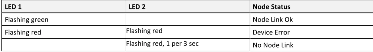
LED Behavior for the Nodes
Nodes do not sample inputs until they are communicating with the Gateway. The nodes and antennas must be a minimum distances apart to function properly. The minimum distance for a 1 Watt, 900MHz node is 15 feet.
LED 1 LED 2 Node Status
Flashing green Node Link Ok
Flashing red Flashing red Device Error
Flashing red, 1 per 3 sec No Node Link
Storage and Sleep Modes
Storage Mode (applies to battery-powered models only)—while in storage mode, the Node does not operate. All Nodes powered from an integrated battery ship from the factory in Storage Mode to conserve the battery. To wake the device, press and hold Button 1 for five seconds. To put any integrated battery Node into Storage Mode, press and hold Button 1 for five seconds. The radio is in Storage Mode when the LEDs stop blinking, but in some models, the LCD display remains on for an additional minute after the radio enters Storage Mode. Wait at least one minute before waking a device that has entered Storage Mode.
Sleep Mode (applies to both battery and 10-30 VDC powered models)—during normal operation, Electrolab Nodes enter Sleep Mode after fifteen minutes of operation. The radio continues to function, but the LCD display goes blank. To wake the device, press any button.
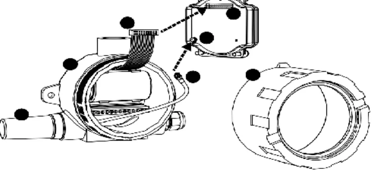
Assembly
Follow these steps to assemble your Electrolab D99 Model 2100 Node. The D99 ships as a complete unit, including the node core, housing, and integrated battery. One terminal header is also included in the shipment. To unpack and wire the unit, follow the steps below.
EL 29158_RevA
Last Updated: 01/2019 © 2019, Electrolab, Inc. All Rights Reserved.
1. Open the end with the glass window (5) and gently lift up the node core unit (4) and the
space frame it sits on. The core unit connects to the space frame using two pins and the node core connects to the wiring board with a ribbon cable.
2. Insert the battery (2) into the battery holder. Position the negative poles of the
battery according to the markings on the board.
3. Install the terminal header (3) onto the terminal pins.
4. Insert your sensor wires through a cable gland and one of the two 1/2-inch NPT
ports. Wire the sensor wires into the terminal header (3) according to the control drawings. Use a cable gland certified for your region and environment. For a waterproof seal, refer to the waterproofing instructions in the applicable product manual.
5. The Model 2100 Node comes with the dome antenna installed. If it is not already
connected, connect the antenna cable (3) to the node unit’s antenna connector (5). (You may need to separate the space frame from the node to do this.)
6. Gently install the ribbon cable (4) into the ribbon cable pins (6), verifying the ribbon
cable seats properly on both rows of pins.
7. Reconnect the space frame (not shown) to the node core unit.
8. Place the node unit into the housing and gently push down until the spacer frame
pin holes rest on the edge of the metal housing.
9. Close the metal cover firmly and lock closed using the set screw.
Figure 2 Installing and Connecting the Antenna
EL 29158_RevA
Last Updated: 01/2019 © 2019, Electrolab, Inc. All Rights Reserved.
Replacing the Battery
To replace the lithium “D” cell battery in the metal housings, follow these steps.
1. Unscrew the lid of the metal enclosure.
2. Lift the node out of the metal enclosure and pull the spacer frame off the back side of
the node.
3. Disconnect the node by unplugging the ribbon cable from the node board and set aside
the node and spacer frame.
4. Remove the discharged battery.
5. Replace with a new battery. Only use a 3.6V lithium battery from Xeno, model number
XL-205F.
6. Confirm that the battery’s positive and negative terminals align to the positive and
negative terminals of the battery holder mounted within the case. CAUTION: There is a risk of explosion if the battery is replaced incorrectly.
7. Wait two minutes.
8. Insert the ribbon cable through the center of the spacer frame. Plug the ribbon cable
back into the node board.
9. Screw on the lid and tighten.
10.After replacing the battery, allow up to 60-seconds for the device to power up.
11.Properly dispose of the used battery according to local regulations by taking it to a
hazardous waste collection site, an e-waste disposal center, or other facility qualified to accept lithium batteries.
WARNING: As with all batteries, these are a fire, explosion, and severe burn hazard. Do
not burn or expose them to high temperatures. Do not recharge, crush, disassemble, or expose the contents to water.
The battery may be replaced in explosive gas atmospheres. For pricing and availability of battery replacements, contact Electrolab.
EL 29158_RevA
Last Updated: 01/2019 © 2019, Electrolab, Inc. All Rights Reserved.
Metal Housing Dimensions
Included with Device (Metal Housing with Dome Antenna)
Qty. Item
Dome Antenna 1 Dome Antenna, 902-928 MHz, 2 dBd Omni, 1/2-inch NPT, 18" cable, or
Dome Antenna, 2.4 GHz, 2 dBd Omni, 1/2-inch NPT, 18" cable
EL 29158_RevA
Last Updated: 01/2019 © 2019, Electrolab, Inc. All Rights Reserved.
Specifications
Radio Range1
900 MHz, 150 mW: Up to 4.8 km (3 miles) 2.4 GHz, 65 mW: Up to 3.2 km (2 miles)
Minimum Separation Distance
900 MHz, 150 mW: 2 m (6 ft) 2.4 GHz, 65 mW: 0.3 m (1 ft)
Transmit Power
900 MHz, 150 mW: 21 dBm (150 mW) conducted
2.4 GHz, 65 mW: 18 dBm (65 mW) conducted, less than or equal to 20 dBm (100 mW) EIRP
900 MHz Compliance
FCC ID TGUDX80 - This device complies with FCC Part 15, Subpart C, 15.247 IC: 7044A-DX8009
2.4 GHz Compliance
FCC ID UE300DX80-2400 - This device complies with FCC Part 15, Subpart C, 15.247 ETSI EN 300 328 V1.8.1 (2012-06) IC: 7044A-DX8024
Supply Voltage
3.6V dc low power option from an internal battery
Power Consumption
Consumption: Application dependent
Housing
Glass and cast aluminum w/ chromating and chemically resistant paint (outside only)
Antenna Connection
Ext. Reverse Polarity SMA, 50 Ohms Max Tightening Torque: 0.45 N·m (4 lbf·in)
Spread Spectrum Technology
FHSS (Frequency Hopping Spread Spectrum)
Interface
Indicators: Two bi-color LEDs Buttons: Two Display: Six character LCD
Wiring Access
Two 1/2-inch NPT ports, one 3/4-inch NPT port (internal threads)
Electrolab Digital Level Sensor Inputs
Float 1, Float 2, and Temp Sample Rate: 2 minutes Float 1, Float 2, and Temp Report Rate: 2 minutes Float 1, Float 2, and Temp Warmup Time: 250 ms Error and Warning Sample Rate: 15 minutes Error and Warning Report Rate: 15 minutes Error and Warning Warmup Time: 250 ms
Environmental Rating
IEC IP68
Operating Conditions2
–40 °C to +65 °C (–40 °F to +149 °F) (Electronics); –20 °C to +80 °C (–4 °F to +176 °F) (LCD)
95% maximum relative humidity (non-condensing) Radiated Immunity: 10 V/m (EN 61000-4-3)
Shock and Vibration
IEC 68-2-6 and IEC 68-2-27
Shock: 30g, 11 millisecond half sine wave, 18 shocks Vibration: 0.5 mm p-p, 10 to 60 Hz
RS-485 Inputs
Interface: 2-wire half-duplex RS-485 Baud Rates: 9.6k, 19.2k (default), or 38.4k
Data Format: 8 data bits, no parity, 1 stop bit (even and odd parity selection are available)
Analog Inputs
Rating for 0-10V inputs: 10 V Rating for 0-5V inputs: 5V Sample Rate: 250 milliseconds Report Rate: 250 milliseconds
Accuracy: 0.1% of full scale +0.01% per °C Resolution: 15-bit
1Radio range is with the 2 dB antenna that ships with the product. High-gain antennas are available, but the range depends on the
environment and line of sight. Always verify your wireless network's range by performing a Site Survey.
EL 29158_RevA
Last Updated: 01/2019 © 2019, Electrolab, Inc. All Rights Reserved.
Certifications
Warnings
Install and properly ground a qualified surge suppressor when installing a remote antenna system. Remote antenna configurations
installed without surge suppressors invalidate the manufacturer's warranty. Keep the ground wire as short as possible and make all ground connections to a single-point ground system to ensure no ground loops are created. No surge suppressor can absorb all lightning strikes; do not touch the Electrolab Wireless Communications Network device or any equipment connected to any of the devices during a
thunderstorm.
Exporting Electrolab Wireless Communications Network Nodes. It is our intent to fully comply with all national and regional regulations
regarding node frequency emissions. Customers who want to re-export this product to a country other than that to which it was sold
must ensure the device is approved in the destination country. A list of approved countries appears in the Node Certifications section of
the product manual. The Electrolab Wireless Communications Network products were certified for use in these countries using the antenna that ships with the product. When using other antennas, verify you are not exceeding the transmit power levels allowed by local governing agencies. Consult with Electrolab, Inc. if the destination country is not on this list.
Any misuse, abuse, or improper application or installation of this product or use of the product for personal protection applications when the product is identified as not intended for such purposes will void the product warranty. Any modifications to this product without prior express approval by Electrolab, Inc. will void the product warranties. All specifications published in this document are subject to change; Electrolab, Inc. reserves the right to modify product specifications or update documentation at any time. For the most recent version of any documentation, refer to: www.electrolabcontrols.com. Electrolab, Inc. All rights reserved.
Limited Warranty
Electrolab, Inc. warrants its products to be free from defects in material and workmanship for 18-months following the date of shipment. Electrolab, Inc. will repair or replace, free of charge, any product of its manufacture which, at the time it is returned to the factory, is found to have been defective during the warranty period. This warranty does not cover damage or liability for misuse, abuse, or the improper application or installation of the Electrolab, Inc. product.
THIS LIMITED WARRANTY IS EXCLUSIVE AND IN LIEU OF ALL OTHER WARRANTIES WHETHER EXPRESS OR IMPLIED (INCLUDING, WITHOUT LIMITATION, ANY WARRANTY OF MERCHANTABILITY OR FITNESS FOR A PARTICULAR PURPOSE), AND WHETHER ARISING UNDER COURSE OF PERFORMANCE, COURSE OF DEALING OR TRADE USAGE.
This Warranty is exclusive and limited to repair or, at the discretion of Electrolab, Inc., replacement. IN NO EVENT SHALL ELECTROLAB,
INC. BE LIABLE TO BUYER OR ANY OTHER PERSON OR ENTITY FOR ANY EXTRA COSTS, EXPENSES, LOSSES, LOSS OF PROFITS, OR ANY INCIDENTAL, CONSEQUENTIAL OR SPECIAL DAMAGES RESULTING FROM ANY PRODUCT DEFECT OR FROM THE USE OR INABILITY TO USE THE PRODUCT, WHETHER ARISING IN CONTRACT OR WARRANTY, STATUTE, TORT, STRICT LIABILITY, NEGLIGENCE, OR OTHERWISE.
Electrolab, Inc. reserves the right to change, modify or improve the design of the product without assuming any obligations or liabilities relating to any product previously manufactured by Electrolab, Inc.
CSA: Class I, Division 1, Groups A, B, C, D; Class II, Division 1, Groups E, F, G; Class III, Division 1 (Ex ia IIC T4 / AEx ia IIC T4) Certificate: 2008243
LCIE/ATEX: Zone 0 (Category 1G) and 20 (Category 1D), Temperature Class T4 (II 1 GD / Ex ia IIC T4 Ga / Ex ia IIIC T82°C Da IP68) Certificate: LCIE 08 ATEX 6098 X
Special Conditions for Safe Use imposed by Intrinsic Safety Certificate LCIE 08 ATEX 6098 X: Ambient temperature range is –40 to 70 °C. Sure Cross® DX99 FlexPower devices can only be connected to Intrinsically Safe certified equipment or simple apparatus as defined by EN 60079-11. All connected equipment must comply with the Entity Parameters (Safety Parameters) listed in the Control Drawings). The device must only use a lithium battery manufactured by XENO, type XL-205F.