Identifier-based adaptive neural dynamic surface control for uncertain
DC–DC buck converter system with input constraint
q
Qiang Chen
a,⇑, Xuemei Ren
a, Jesus Angel Oliver
b aSchool of Automation, Beijing Institute of Technology, Beijing 100081, PR China b
Centro de Electronica Industrial, Universidad Politcnica de Madrid (UPM), Madrid 28006, Spain
a r t i c l e
i n f o
Article history:
Received 29 April 2011 Accepted 19 August 2011 Available online 7 September 2011
Keywords:
Adaptive dynamic surface control Neural compensator
Buck converter Finite-time identifier
a b s t r a c t
In this paper, an identifier-based adaptive neural dynamic surface control (IANDSC) is pro-posed for the uncertain DC–DC buck converter system with input constraint. Based on the analysis of the effect of input constraint in the buck converter, the neural network compen-sator is employed to ensure the controller output within the permissible range. Subse-quently, the constrained adaptive control scheme combined with the neural network compensator is developed for the buck converter with uncertain load current. In this scheme, a newly presented finite-time identifier is utilized to accelerate the parameter tuning process and to heighten the accuracy of parameter estimation. By utilizing the adap-tive dynamic surface control (ADSC) technique, the problem of ‘‘explosion of complexity’’ inherently in the traditional adaptive backstepping design can be overcome. The proposed control law can guarantee the uniformly ultimate boundedness of all signals in the closed-loop system via Lyapunov synthesis. Numerical simulations are provided to illustrate the effectiveness of the proposed control method.
Crown CopyrightÓ2011 Published by Elsevier B.V. All rights reserved.
1. Introduction
DC–DC converters are inherently time-variant systems and widely applied in many fields, such as power electronics, automatic control and so on[1]. The control problem of DC–DC converters has been investigated in recent years. There are three main types of DC–DC power converters, which are called buck, boost, and buck–boost converters. From an automatic control viewpoint, a switching power converter can be regarded as a variable structure nonlinear system, and described by a state-space averaging (SSA) model[2,3]or a Hammerstein model[4].
Since linear controllers that take advantage of the conventional PI approach are very sensitive to the parameter variations, some nonlinear control methods have been developed[5–12]. In[5,6], nonadaptive and adaptive passivity-based controllers with complex structures are designed for the converters with known and unknown load resistances, respectively. A simpli-fied PD passivity based controller is proposed in[7]to improve the controller structure. However, the passivity methods may not guarantee the good robustness when the load is varying largely because the parameters need to be redesigned when the large load variation takes place. Recently, sliding mode control (SMC) schemes are employed for the DC–DC power convert-ers to enhance the robustness of the control systems[8–10]. But most sliding mode controllers are with relatively complex structures[11]. In[12,13], the adaptive backstepping technique is utilized to design the nonlinear controller such that good set-point control (i.e., the desired output is a constant) performance can be achieved. However, the serious ‘‘explosion of
1007-5704/$ - see front matter Crown CopyrightÓ2011 Published by Elsevier B.V. All rights reserved. doi:10.1016/j.cnsns.2011.08.028
q
Supported by the National Natural Science Foundation of China under Grant Nos. 60974046 and 61011130163.
⇑Corresponding author. Tel.: +86 10 68914506.
E-mail address:[email protected](Q. Chen).
Contents lists available atSciVerse ScienceDirect
Commun Nonlinear Sci Numer Simulat
j o u r n a l h o m e p a g e : w w w . e l s e v i e r . c o m / l o c a t e / c n s n scomplexity’’ problem existing in the backstepping technique will increase the controller complexity due to the repeated dif-ferentiations of virtual controllers.
Although nonlinear controllers can improve the dynamic performance of the power converters, most controller structures are quite complex, which may block their further application in practice[14]. To simplify the controller structure and over-come the ‘‘explosion of complexity’’ in the backstepping design, the dynamic surface control (DSC) scheme is proposed by introducing a first-order filtering of the synthesized virtual control law at each step of the traditional backstepping approach
[15–18]. To the best of our knowledge, the DSC method has been seldom used in the control of DC–DC power converters yet. Based on a general SSA model with considering the effect of lossy components[19], we present a simple adaptive dynamic surface controller for the uncertain buck converter by incorporating a newly developed finite-time identifier to improve the set-point control and parameter estimation performance. Furthermore, in order to produce effective duty-ratio signals based on the pulsewidth-modulation (PWM), the controller output should be constrained in a certain range[20]. Thus, the neural network compensator is employed such that the constrained control can be achieved[21].
In this paper, neural adaptive dynamic surface control based on the finite-time identifier is proposed for the uncertain DC–DC synchronous buck converter system with input constraint. The main contributions of the paper are as follows:
1. We build the state-space averaging model with considering the load current and the equivalent series resistances (ESR) of the capacitor. The proposed model can describe the dynamic response of the converter system where the load resistance varies largely.
2. The improved adaptive dynamic surface control approach is proposed for the set-point control of buck converter system. By introducing a newly developed finite-time identifier into the adaptive dynamic surface control, the set-point control and parameter estimation performance can be improved without increasing the controller complexity.
3. The neural network compensator is employed to compensate for the error between the controller output and constrained controller output to guarantee that the control signal can be guaranteed within the permissible range [0, 1] and the con-trol response speed is enhanced when the concon-trol parameter is set inappropriately.
The rest of this paper is organized as follows. Section2presents the problem formulation and preliminaries. In Section3, the identifier-based adaptive neural dynamic surface control (IANDSC) method is proposed for the uncertain buck converter system. The stability analysis of the proposed control is given in Section4. Simulation results are provided to show the effec-tiveness of the proposed control in Section5. Section6contains the conclusion.
2. Problem formulation
2.1. System description
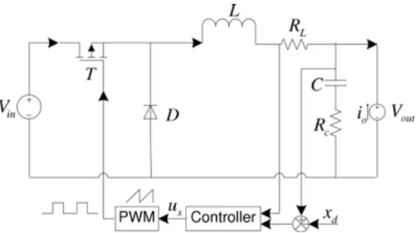
As shown inFig. 1, the set-point control of PWM-based DC–DC buck converter with an adjustable load is described, where the converter is assumed to operate in continuous conduction mode (CCM). It can be seen that the buck converter is consti-tuted of an input voltage sourceVin, a triodeT, a diodeD, load current sourceio, inductorLwith ESR,RLand capacitorCwith ESR,Rc.
The operation process of the buck converter can be described according to the Pulse Width Modulation (PWM) principle
[20]. The time is shared in intervals of sampling periodTs. Within one sampling period, the triodeTis conducting during a period fractionusT, whereo6us61 is called duty-ratio. Consequently, the diodeDis blocked and the voltage sourceVin provides the energy to the whole buck converter system. During the rest of the sampling period,i.e.(1us)T, the triodeT is closed and the diodeDis conducting which can guarantee the continuity of the current and the discharge of inductance in load. The output voltageVoutmay therefore be lower than the input voltageVin. It should be noted that the value ofus varies from a sampling period to another and the value of output voltageVoutis determined by the variation law ofus.
The dynamic equations for the circuit configuration can be expressed in the standard state-space form, where the capac-itor voltageVCand inductor currentiLare selected as the two state variables andusis the constrained control input. We can derive the averaging reduced slow model through the dynamics of the circuit for ON and OFF conditions of the transistorsT andD, respectively. By applying the well-known averaging method[20], we have the state-space averaging (SSA) model as follows. _ x¼fðx;uÞ þgðx;uÞh ð1Þ with fðx;uÞ ¼ 1 Cx2; 1 LusVinx1x2Rc T ð2Þ and gðx;uÞ ¼ 1 C; Rc L T ; ð3Þ
wherex= [x1x2]Tare the state variables, which represent capacitor voltageVcand inductor currentiL.usis the constrained control input andhrepresents the unknown load currentio.
It is worth noting that the effect of inductor ESR,RL, is ignored while the effect of capacitor ESR,Rc, is considered in the SSA model(1). This is different from the ideal SSA model, whereRcandRLare both ignored[12,13]. Furthermore, the load resis-tanceRois replaced by the load currentiofor the analyzing convenience of the large variation of load resistance.
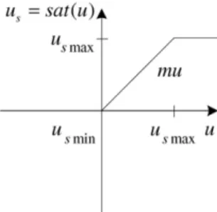
2.2. Magnitude limiter
In order to constrain the control signal within the permissible range [0, 1], we set a magnitude limiter in the controller design.Fig. 2shows the magnitude limiterus=sat(u), whereuandusare controller output and constrained controller output, respectively. In this paper, the limiter is assumed to be unknown and to have a linear form with a unity ratio betweenusand u. The upper and lower bounds of the limiter are defined asusmax= 1 andusmin= 0, respectively.
As shown inFig. 2, the constrained controller output can be expressed as
usðtÞ ¼
usmax: uðtÞ>usmax; uðtÞ: usmin6uðtÞ6usmax; usmin: uðtÞ<usmin: 8
> < >
: ð4Þ
From(4), we can obtain that the magnitude limiter will take effect when the controller outputu(t) falls outside the range of [usminusmax]. Then the errord(t) betweenuandusis defined as
dðtÞ ¼usðtÞ uðtÞ ¼
usmaxuðtÞ: uðtÞ>usmax; 0: usmin6uðtÞ6usmax; usminuðtÞ: uðtÞ<usmin: 8
> < >
: ð5Þ
2.3. Neural network compensator
Due to the good capabilities in function approximation, neural networks (NNs) are usually used as a tool for modeling nonlinear functions[22–26]. Given a compact setXzRl, the following NN is employed to approximate the error function d(z):
dnnðzÞ ¼WTSðzÞ; ð6Þ
whereW= [
x
1,x
2,. . .,x
l]T2Rlis the weight vector.l> 1 is the NN node number.z= [z1,. . .,zl]T2Xzis an input vector and S(z) = [S(z1),S(z2),. . .,S(zl)]Tis a sigmoid function with the following formSðzÞ ¼ a
bþeðz=cÞþd ð7Þ
witha,b,canddbeing appropriate parameters.
From(6), it is obtained that the NN can compensate ford(z) as
dðzÞ ¼WTSðzÞ þ
; ð8Þ
whereWis the ideal constant weight, and
=d(z)dnn(z) is the compensation error.Remark 1. In this paper, the ideal NN weightWand the compensation error
are assumed to be bounded,i.e.,kWk6Wmandj
j6m, withWmandmbeing known constants.2.4. Finite-time parameter identification
In this subsection, the finite-time parameter identification mechanism is briefly introduced. For more design details, please see[27,28].
Let^xbe the state predictor for(1)with dynamics
_^
x¼fðx;uÞ þgðx;uÞh0þkmðx^xÞ; ð9Þ
whereh0is the nominal initial estimate ofhandkm> 0 is a design matrix. Defining the auxiliary variable
g
¼x^xm
ðhh0Þ ð10Þand choosing the filter dynamic as
_
m
¼gðx;uÞ km
;m
ðt0Þ ¼0; ð11Þwe can obtain the following lemma.
Lemma 1 [28]. Let Q12R and Q22R be generated from the following dynamics:
_ Q1¼
m
Tm
; Q1ðt0Þ ¼0; _ Q2¼m
Tðm
h0þx^xg
Þ; Q2ðt0Þ ¼0; ( ð12Þand let tcbe the time such that Q1(t0)0, then the finite-time adaptation law
_^
h¼
C
ðQ2Q1^hÞ ¼C
Q1~h; ^hðt0Þ ¼h0; ð13ÞwithC=CT
0 guarantees thatk~hk ¼ k^hhkis non-increasing for t06t6tcand converges to zero exponentially fast, starting from tc. Furthermore, the convergence rate is lower bounded byf(t) =kmin(CQ1(t)).
Proof of Lemma 1.See[28]. h
The control objective of this paper is to design the adaptive neural dynamic surface control based on the finite-time param-eter identification for the uncertain buck converter with input constraint such that the output voltage can track the reference value fast and all signals in the closed-loop system are guaranteed to be uniformly ultimately bounded.
3. Identifier-based adaptive neural dynamic surface control
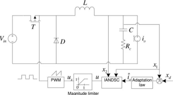
In this section, the identifier-based adaptive neural dynamic surface control (IANDSC) is proposed for the uncertain DC– DC buck converter(1)with input constraint. The newly developed finite-time parameter identifier(13)is adopted in the adaptation law of the unknown load current. Similar to the traditional backstepping design, the virtual controls and practical controls are constructed in the recursive procedures. The whole control structure is shown inFig. 3.
The first surface error is defined as
e1¼x1xd; ð14Þ
From(1), the time derivative ofe1is
_
e1¼x_1x_d¼
1
Cðx2ioÞ x_d: ð15Þ
Choosex2as a virtual controller to stabilize(15)
x2¼^ioþCx_dk1e1; ð16Þ
wherek1is a positive design parameter.
Instead of usingx2x2directly as the second error signal in the general backstepping design (see the appendix),x2is
passed through a first order filter with time constant
s
2and we can obtain a new state variablex2d,s
2x_2dþx2d¼x2; x2dð0Þ ¼x2ð0Þ: ð17ÞThen, the second surface error is defined as
e2¼x2x2d: ð18Þ
Differentiatinge2along(1) and (5), we can obtain
_
e2¼x_2x_2d¼
1
L½ðuþdÞVinx1 ðx2ioÞRc x_2d: ð19Þ
Thus, the controlucan be designed as
u¼uf^d; ð20Þ
whereufis the set-point control law and^dis the estimation ofd. The expressions ofufanddare given as follows:
uf ¼ 1 Vin ½x1þ ðx2^ioÞRcþLx_2d k2e2; ð21Þ and ^ d¼W^TSðzÞ; ð22Þ
wherek2is a positive design parameter.W^ is the estimation of NN weightW.z2Xzis the input vector. According to finite-time identification mechanism(9)–(13), the adaptation law of^iois designed as
_^ io¼ 1 LRce2 1 Ce1þQ2Q1 ^i o¼ 1 LRce2 1 Ce1Q1 ~i o; ð23Þ
whereQ1andQ2are generated from(12).
The adaptation law ofW^ is given as
_^
W¼
C
SðzÞVin L e2r
W^
; ð24Þ
whereC=CT0 is the learning rate matrix,z2X
zis the input vector, and
r
is a positive constant. Fig. 3.The constrained adaptive control system.4. Stability analysis
In this section, the stability analysis for the proposed adaptive neural dynamic surface control is given based on Lyapunov theory.
First of all, define three error variables as
y2¼x2dx2; ð25Þ ~i o¼^ioio; ð26Þ and ~ W¼W^ W: ð27Þ
Then, from(15) and (16), the derivative ofy2is
_ y2¼x_2dx_2¼1
s
2ð x2x2dÞ ð_^ioþC€xdk1e_1Þ ¼ 1s
2 y2þ/ðe1;e2;y2;^io;xd;x_d;€xdÞ; ð28Þ where /ðe1;e2;y2;^io;xd;x_d;x€1dÞ ¼ _^ioC€xdþk1e_1: ð29ÞFor simplicity,/ðe1;e2;y2;^io;xd;x_d;€xdÞis denoted as/in the following discussions, and/is assumed to be bounded by j/j</m, where/mis a positive constant.
Remark 2.The objective of this paper is to control the load voltageVoto track a desired valuexd. FromFig. 1, we have Vo=Vc+icRc. In most practical situations, the statex1can be taken as theVosinceicRcVc[18]. Thus, the control objective is equal to design the IANDSC to drivex1to trackxdwith arbitrarily small surface errors.
Theorem 1. Consider uncertain buck converter system consisting of system model(1), controllers(20)–(22)and adaptation laws (23) and (24). Then, for given bounded initial conditions, all signals in the system(1)are uniformly ultimately bounded, and the surface errors ei, i = 1, 2 can be made arbitrarily small by selecting design parameters properly.
Proof.Construct the following Lyapunov function
V¼1 2ðe 2 1þe22þy22þ~i2oþW~T
C
1W~ Þ: ð30ÞFrom(15), (18)–(20), (25) and (28), the time derivative ofVcan be expressed as
_ V¼e1e_1þe2e_2þy2y_2þ~io_~ioþW~TC1W_~ ¼e1 1 Cðx2ioÞ x_1d þe2 1 L½ðuþdÞVinx1 ðx2ioÞRc x_2d þy2 1
s
2 y2þ/ þ~io_~ioþW~TC1W_~ ¼e1 1 Cðe2þx2dx2þx2ioÞ x_1d þe2 1 L½ðuf^dþdÞVinx1 ðx2ioÞRc x_2d þy2 1s
2 y2þ/ þ~io_~ioþW~TC1W_~ ¼e1 1 Cðe2þy2þx2ioÞ x_1d þe2 1 L½ðuf^dþdÞVinx1 ðx2ioÞRc x_2d þy2 1s
2 y2þ/ þ~io_~ioþW~TC1W_~: ð31Þ Using(16), (21) and (22), we can obtain_ V¼1 Ce1ðe2þy2þ^ioiok1e1Þ þe2 Vin L ðW T SðZÞ W^TSðZÞ þ
Þ þ1 L½ðio^ioÞRck2Vine2 þy2 1
s
2 y2þ/ þ~io_^ioþW~TC
1W_^ ¼ k1 Ce 2 1 k2Vin L e 2 2þ 1 Ce1e2þ 1 Ce1y2 1s
2 y2 2þy2/þ 1 Ce1 ~i o 1 Le2Rc ~i oþ~io_^io Vin L e2W~ TSðZÞ þW~TC
1W_^ þVin L e2 ¼ k1 Ce 2 1 k2Vin L e 2 2þ 1 Ce1e2þ 1 Ce1y2 1s
2 y2 2þy2/þ~io _^ioþ 1 Ce1 Rc Le2 þW~TC
1 W_^C
SðZÞVin L e2 þVin L e2: ð32ÞSubstituting(23) and (24)into(32)yields _ V¼ k1 Ce 2 1 k2Vin L e 2 2þ 1 Ce1e2þ 1 Ce1y2 1
s
2 y2 2þy2/Q1~i2or
W~TW^ þ Vin L e2 6k1 Ce 2 1 k2Vin L e 2 2þ 1 Cje1jje2j þ 1 Cje1jjy2j 1s
2 y2 2þ jy2jj/j Q1~i2or
W~ TW^ þVin L je2jm: ð33ÞEmploying the inequalities
r
W~TW^ ¼r
W~T ðW~ þWÞ61 2r
kWk~ 2 þ1 2r
W 2 m; ð34Þ and je1jje2j6e21þ 1 4e 2 2; je1jjy2j6e21þ14y 2 2; je2jm6e22þ14 2 m; 8 > < > : ð35Þthe inequality(33)can be rewritten as
_ V6k1 Ce 2 1 k2Vin L e 2 2þ 1 C 2e 2 1þ1 1 4e 2 2þ 1 4y 2 2 1
s
2 y2 2þ jy2jj/j Q1~i2o 1 2r
kWk~ 2 þ1 2r
W 2 mþ 1 4 2 m: ð36ÞWe have the following fact
jy2jj/j6 1 2ny 2 2j/j 2 þn 2 ð37Þ
withn> 0 any positive constant, and thus
1 4Cy 2 2 1
s
2 y2 2þ jy2jj/j6 1 4Cþ /2m 2n 1s
2 ! y2 2þ n 2: ð38Þ Chooses
2,k1,k2so that 1s
2¼ 1 4Cþ /2m 2nþq
; ð39Þ and k1¼2þq
; k2¼4CV5L inþq
; ( ð40Þwhere
q
is a positive constant. Then, lettingq
¼min Q1;12r
, the following inequality can be obtained
_ V61 C
q
e 2 1 Vin Lq
e 2 2q
y 2 2Q1~i2o 1 2r
kWk~ 2 þ1 2r
W 2 mþ 1 4 2 mþ 1 2n 61 Cq
e 2 1 Vin Lq
e 2 2q
y 2 2q
~i 2 oq
kWk~ 2 þ1 2r
W 2 mþ 1 4 2 mþ 1 2n¼ 2a
Vþb; ð41Þ wherea
¼min 1 Cq
; Vin Lq
;q
; ð42Þ and b¼1 2r
W 2 mþ 1 4 2 mþ 1 2n: ð43Þ Letc
¼ba, integrating(41)from0tot, we have
VðtÞ6Vð0Þe2atþ
c
: ð44ÞFrom(44), it is obvious thatV(t) can be eventually bounded by
c
. Thus, all signals in the closed-loop system, such ase1,e2,y2, ~ithat the statesxi(i= 1, 2) remain bounded. From(20)–(22), it can be conclude that controluis also bounded. Thus, all signals in the buck converter(1)are uniformly ultimately bounded. Furthermore,(44)gives
lim
t!1VðtÞ
6
c
; ð45Þwhich implies that increasing
a
can lead to a smallerc
, and thus the surface errorsei,i= 1, 2 can converge to an arbitrarily small residual set.This completes the proof. h
Remark 3. For the buck converter considered in this paper, the values ofLandCare generally much smaller thanVinand 1, respectively. Thus,(42)can be expressed as
a
=q
for convenience. From(39) and (40), we can see that increasingki,i= 1, 2 or decreasings
2can lead to a largera
, which can help to reducec
. However, smallers
2may also lead to a higher control gain.Thus,
s
2must be chosen as a tradeoff. Moreover,r
should be chosen properly since increasingr
can simultaneously increasea
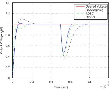
andb. 0 0.2 0.4 0.6 0.8 1 x 10⁻³ 0 0.2 0.4 0.6 0.8 1 1.2 1.4 Time (sec) Output Voltage x 1 (V) Desired Voltage Backstepping ADSC IADSCFig. 4.Set-point control performance of output voltage.
0 0.2 0.4 0.6 0.8 1 x 10⁻³ −1 −0.5 0 0.5 1 1.5 2 2.5 Time (sec) Output Current i o (A) Desired Current Backstepping ADSC IADSC
5. Simulation results
In this section, some numerical simulations are performed to evaluate the performances of the proposed adaptive dy-namic surface controller and neural network compensator. The total simulation time is 1 ms with the time interval ts = 104ms. The initial conditions and relevant parameters are set as follows.
In the buck converter system,x1(0) =x2(0) = 0; the switching frequency is set to be 500 kHz, and the sampling frequency
is 104kHz; the circuit parameters areV
in= 3 V,xd= 1 V,C= 50
l
F,L= 700 nH andRc= 50 mX, respectively; the load current iois unknown and set to vary from 0 A to 2 A at the time 0.5 ms. The design parameters of the controller are chosen asq
= 0.06, k1= 2.06, k2= 0.0658. The parameters of the neural network compensator are set asr
= 0.001, a= 1.5, b= 1,c= 0.5, d=1.6, z¼ ½xd;x2d;e1;e2;r_;x_2d, C= 0.001I66, i= 1, 2,. . ., 6. The km of the finite-time identifier is selected as km= 100I22and the design parameters of the backstepping controller arek01¼k
0
2¼2 and
r
0= 0.01.It is worth noting that the time constant
s
2of the first order filter is significant to the adaptive dynamic surface controlscheme. In the following, we will discuss the proposed control and parameter identification performances in two cases according to the selection of
s
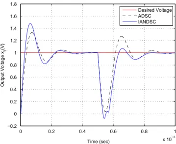
2.0 0.2 0.4 0.6 0.8 1 x 10⁻³ −0.2 0 0.2 0.4 0.6 0.8 1 1.2 1.4 1.6 1.8 Time (sec) Output Voltage x 1 (V) Desired Voltage ADSC IANDSC
Fig. 6.Set-point control performance of output voltage.
0 0.2 0.4 0.6 0.8 1 x 10⁻³ −0.5 0 0.5 1 1.5 2 2.5 Time (sec) Output Current i o (A) Desired Current ADSC IANDSC
5.1. Case 1:
s
2= 105When the filter parameter
s
2is selected properly ass
2= 105, the NN compensator does not take effect because thecon-trol input is inside the range [0, 1], thus we can obtaind= 0 andus=u.Figs. 4 and 5show the comparisons of set-point control and parameter identification performances among the proposed identifier-based adaptive dynamic surface control (IADSC), adaptive dynamic surface control (ADSC) without finite-time identifier and general backstepping control described in the appendix. FromFigs. 4 and 5, we can see clearly that the proposed IADSC owns a better set-point control performance and faster parameter identification speed.
However, it may be difficult and time-consuming in order to choose a proper
s
2in practice. To further illustrate theeffec-tiveness of the proposed neural network compensator,
s
2is set inappropriately ass
2= 3105in the following simulations.5.2. Case 2:
s
2= 3105In this case,
s
2is selected inappropriately and the adaptive dynamic surface control without NN compensator is used tocompare the performance. The simulation results are shown inFigs. 6–9.Fig. 6shows the set-point control compare perfor-mance of output voltage with and without the NN compensator. The compare perforperfor-mance of parameter identification is
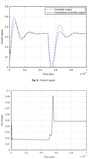
0 0.2 0.4 0.6 0.8 1 x 10⁻³ 0 0.1 0.2 0.3 0.4 0.5 0.6 Time (sec) Control signal Controller output
Constrained controller output
Fig. 8.Control signal.
0 0.2 0.4 0.6 0.8 1 x 10⁻³ 0 0.01 0.02 0.03 0.04 0.05 0.06 0.07 0.08 0.09 0.1 Time (sec) NN Weight
provided inFig. 7. The controller output and constrained controller output of IANDSC are shown inFig. 8.Fig. 9gives the output of NN. FromFigs. 6–9, we can see that the proposed IANDSC has better control and identification performances than ADSC when the filter parameter
s
2is selected inappropriately.6. Conclusion
In this paper, an adaptive neural dynamic surface control method based on a novel finite-time identification has been pro-posed for the uncertain DC–DC buck converter system with input constraint. Based on the state-space averaging model built by load current and ESR of the capacitor, a constrained adaptive dynamic surface controller combined with the finite-time identification is designed to improve the set-point control and parameter identification performances. The error between the controller output and constrained controller output is approximated by the neural network. The proposed control can be eas-ily extended to the set-point and tracking control for some other nonlinear systems such as boost converter, buck–boost con-verter and so on.
Acknowledgment
The authors would thank the support from the National Natural Science Foundation of China under Grant Nos. 60974046 and 61011130163.
Appendix A
In this section, the general backstepping controller is designed in the following two steps.
Step 1. Two error variables are defined as follows:
e1¼x1xd; e2¼x2x2; ðA:1Þ and ~i o¼^ioio; ðA:2Þ
wherexdis the desired voltage,^iois the estimate ofioandx2is a virtual control which can be developed in the following
steps.
From(1), the derivation ofe1is given by
_
e1¼x_1x_d¼
1
Cðx2ioÞ x_d: ðA:3Þ
Choose the virtual controlx2as
x2¼^ioþCx_dk01e1; ðA:4Þ
wherek01is a design parameter.
Construct the following Lyapunov function candidate:
U1¼ 1 2e
2
1: ðA:5Þ
Then, the time derivative ofU1is obtained by using(A.1)–(A.4)as
_ U1¼e1e_1¼e1 1 Cðe2þx2ioÞ x_d ¼e1 1 Cðe2þ ^i oþCx_dk 0 1e1ioÞ x_d ¼1 Ce1e2þ 1 Ce1 ~i o k01 Ce 2 1: ðA:6Þ Step 2. Taking the time-derivative ofe2along(A.1)and noting(1) and (A.4), it follows that
_ e2¼x_2x_2¼ 1 L½usVinx1 ðx2ioÞRc _^ioþC€x1dk 0 1e_1 ¼1 L½usVinx1 ðx2ioÞRc _^ioþC€x1d k01 Cðe2þ~iok 0 1e1Þ : ðA:7Þ
Here, the controlusis designed as
us¼ 1 Vin x1þ ðx2^ioÞRcþL _^ioþC€x1d k01 C e2þ ~i ok01e1 L CVin e1k02e2; ðA:8Þ
Substituting(A.8)into(A.7), we have _ e2¼ 1 LRc~io 1 Ce1 Vin L k 0 2e2: ðA:9Þ
Consider the following Lyapunov function candidate:
U2¼U1þ 1 2e 2 2þ 1 2~i 2 o: ðA:10Þ The derivative ofU2is _ U2¼U_1þe2e_2þ~io_~io¼ 1 Ce1e2þ 1 Ce1~io k01 Ce 2 1þe2 1 Ce1 1 LRc~io Vin L k 0 2e2 þ~io_^io ¼ k 0 1 Ce 2 1 Vin L k 0 2e 2 2þ~io _^io 1 LRce2þ 1 Ce1 : ðA:11Þ
Choose the following adaptation law
_^ io¼ 1 LRce2 1 Ce1
r
0^i o; ðA:12Þwhere
r
0is a positive constant.Substituting(A.10)into(A.9),U_2can be rewritten as
_ U2¼ k01 Ce 2 1 Vin L k 0 2e 2 2
r
0^i o~io6 k01 Ce 2 1 Vin L k 0 2e 2 2 1 2r
0~i2 oþ 1 2r
0i2 o62a
0U 2þb0; ðA:13Þ wherea
0¼min k0 1 C; Vin L k 0 2;12r
0 n o andb0¼1 2r
0i 2 o.LetU=U2, and we can obtain by solving(A.13)
UðtÞ6Uð0Þe2a0tþ
c
0 ðA:14Þwith
c
0¼b0a0.
Finally, it can be concluded from(A.14)that
lim
t!1UðtÞ
6
c
0: ðA:15ÞReferences
[1] Oliva AR, Ang SS, Bortolotto GE. Digital control of a voltage-mode synchronous buck converter. IEEE Trans Power Electron 2006;21(1): 157–63.
[2] Davoudi A, Jatskevich J, Rybel TD. Numerical state-space average-value modeling of PWM DC–DC converters operating in DCM and CCM. IEEE Trans Power Electron 2006;21(4):1003–12.
[3] Davoudi A, Jatskevich J. Realization of parasitics in state-space average-value modeling of PWM DC–DC converters. IEEE Trans Power Electron 2006;21(4):1142–7.
[4] Alonge F, D’Ippolito F, Raimondi FM, Tumminaro S. Nonlinear modeling of DC/DC converters using the Hammerstein’s approach. IEEE Trans Power Electron 2007;22(4):1210–21.
[5] Sira-Ramirez H, Perez-moreno R, Ortega R, Garcia-Esteban M. Passivity-based controllers for the stabilization of DC-to-DC power converters. Automatica 1997;39:499–513.
[6] Sira-Ramirez H, Ortega R, Garcia-Esteban M. Adaptive passivity-based control of average dc-to-dc power converter models. Int J Adapt Control Signal Process 1998;12:63–80.
[7] Chan Chok-You. Simplified parallel-damped passivity-based controllers for DC–DC power converters. Automatica 2008;44:2977–80.
[8] Sira-Ramirez H, Escobar G, Ortega R. On passivity-based sliding mode control of witched DC-to-DC power converters. In: Proceedings of the 35th IEEE conference on decision and control, Kobe, Japan, December, 1996. p. 2525–6.
[9] Tan SC, Lai YM, Tse CK, Cheung MKH. A fixed-frequency pulse-width-modulation based quasi-sliding mode controller for buck converters. IEEE Trans Power Electron 2005;20(6):1379–92.
[10] Tan SC, Lai YM, Tse CK, Cheung MKH. Adaptive feed-forward and feedback control schemes for sliding mode controlled power converters. IEEE Trans Power Electron 2006;21(1):182–92.
[11] Tan SC, Lai YM, Tse CK. General design issues of sliding-mode controllers in DC–DC converters. IEEE Trans Power Electron 2008;55(3): 1160–74.
[12] EL Fadil H, Giri F, Haloua M, Ouadi H. Nonlinear and adaptive control of buck power converters. In: Proceedings of the 42nd IEEE conference on decision and control, Maul, Hawaii USA, December 2003. p. 4475–80.
[13] Lin SC, Tsai CC. Adaptive backstepping control with integral action for PWM buck DC–DC converters. In: Proceedings of the 2004 IEEE Asia–Pacific conference on circuits and systems, Tainan, Taiwan, December 2004. p. 753–6.
[14] Liu YF, Meyer E, Liu XD. Recent developments in digital control strategies for DC/DC switching power converters. IEEE Trans Power Electron 2009;24(11):2567–77.
[15] Swaroop D, Gerdes JC, Yip PP, Hedrick JK. Dynamic surface control of nonlinear systems. In: Proceedings of the American control conference, Albuquerque, New Mexico USA, June 1997. p. 3028–34.
[16] Swaroop D, Hedrick JK, Yip PP, Gerdes JC. Dynamic surface control for a class of nonlinear systems. IEEE Trans Autom Control 2000;45(10): 1893–9.
[17] Yip PP, Hedrick JK. Adaptive dynamic surface control: a simplified algorithm for adaptive backstepping control of nonlinear systems. Int J Control 1998;71(5):959–79.
[18] Wang D, Huang J. Neural network-based adaptive dynamic surface control for a class of uncertain nonlinear systems in strict-feedback form. IEEE Trans Neural Networks 2005;16(1):195–202.
[19] Pitel Grant E, Krein Philip T. Minimum-time transient recovery for DC–DC converters using raster control surfaces. IEEE Trans Power Electron 2009;24(12):2692–703.
[20] Erickson Robert W. Fundamentals of power electronics. 2nd ed. Secaucus, NJ, USA: Khwer Academic Publishers; 2000.
[21] Gao W, Selmic Rastko R. Neural network control of a class of nonlinear systems with actuator saturation. IEEE Trans Neural Networks 2006;17(1):147–56.
[22] Ge Shuzhi S, Wang Cong. Direct adaptive NN control of a class of nonlinear systems. IEEE Trans Neural Networks 2002;13(1):214–21.
[23] Ren XM, Rad AB. Identification of nonlinear systems with unknown time delay based on time delay neural networks. IEEE Trans Neural Networks 2007;18(5):1536–41.
[24] Ren XM, Lewis FL, Zhang JL. Neural network compensation control for mechanical systems with disturbances. Automatica 2009;45(5):1221–6. [25] Ren XM, Rad AB. Adaptive nonlinear compensation control based on neural networks for nonlinear systems with time delay. Int J Syst Sci
2009;40(12):1283–92.
[26] Na J, Herrmann G, Ren XM. Adaptive discrete neural observer design for nonlinear systems with unknown time-delay. Int J Robust Nonlinear Control 2011;21(6):625–47.
[27] Adetola V, Guay M. Finite-time parameter estimation in adaptive control of nonlinear systems. IEEE Trans Autom Control 2008;53(3):807–11. [28] Adetola V, Guay M. Performance improvement in adaptive control of linearly parameterized nonlinear systems. IEEE Trans Autom Control