Part VI — Fuel Gas
CHAPTER 24
FUEL GAS
The text of this chapter is excerpted from the 2006 edition of theInternational Fuel Gas Codeand has been modified where neces-sary to make such text conform to the scope of application of theInternational Residential Code for One- and Two-Family Dwell-ings. The section numbers appearing in parentheses after each section number represent the location of the corresponding text in the
International Fuel Gas Code.
SECTION G2401 (101) GENERAL
G2401.1 (101.2) Application.This chapter covers those
fuel-gas piping systems, fuel-fuel-gas utilization equipment and related accessories, venting systems and combustion air configurations most commonly encountered in the construction of one- and two-family dwellings and structures regulated by this code.
Coverage of piping systems shall extend from the point of delivery to the outlet of the equipment shutoff valves (see “Point of delivery”). Piping systems requirements shall include design, materials, components, fabrication, assembly, installa-tion, testing, inspecinstalla-tion, operation and maintenance. Require-ments for gas utilization equipment and related accessories shall include installation, combustion and ventilation air and venting and connections to piping systems.
The omission from this chapter of any material or method of installation provided for in theInternational Fuel Gas Code
shall not be construed as prohibiting the use of such material or method of installation. Fuel-gas piping systems, fuel-gas utili-zation equipment and related accessories, venting systems and combustion air configurations not specifically covered in these chapters shall comply with the applicable provisions of the
International Fuel Gas Code.
Gaseous hydrogen systems shall be regulated by Chapter 7 of theInternational Fuel Gas Code.
This chapter shall not apply to the following: 1. Liquified natural gas (LNG) installations.
2. Temporary LP-gas piping for buildings under con-struction or renovation that is not to become part of the permanent piping system.
3. Except as provided in Section G2412.1.1, gas piping, meters, gas pressure regulators, and other appurte-nances used by the serving gas supplier in the distri-bution of gas, other than undiluted LP-gas.
4. Portable LP-gas equipment of all types that is not con-nected to a fixed fuel piping system.
5. Portable fuel cell appliances that are neither con-nected to a fixed piping system nor interconcon-nected to a power grid.
6. Installation of hydrogen gas, LP-gas and compressed natural gas (CNG) systems on vehicles.
SECTION G2402 (201) GENERAL
G2402.1 (201.1) Scope.Unless otherwise expressly stated, the
following words and terms shall, for the purposes of this chap-ter, have the meanings indicated in this chapter.
G2402.2 (201.2) Interchangeability.Words used in the
pres-ent tense include the future; words in the masculine gender include the feminine and neuter; the singular number includes the plural and the plural, the singular.
G2402.3 (201.3) Terms defined in other codes.Where terms
are not defined in this code and are defined in theInternational Code Council Electrical Code—Administrative Provisions, International Building Code, International Fire Code, Interna-tional Mechanical CodeorInternational Plumbing Code, such terms shall have meanings ascribed to them as in those codes.
SECTION G2403 (202) GENERAL DEFINITIONS
AIR CONDITIONING, GAS FIRED.A gas-burning,
auto-matically operated appliance for supplying cooled and/or dehumidified air or chilled liquid.
AIR, EXHAUST.Air being removed from any space or piece
of equipment and conveyed directly to the atmosphere by means of openings or ducts.
AIR-HANDLING UNIT.A blower or fan used for the
pur-pose of distributing supply air to a room, space or area.
AIR, MAKEUP. Air that is provided to replace air being
exhausted.
ALTERATION.A change in a system that involves an
exten-sion, addition or change to the arrangement, type or purpose of the original installation.
ANODELESS RISER.A transition assembly in which plastic
piping is installed and terminated above ground outside of a building.
APPLIANCE (EQUIPMENT).Any apparatus or equipment
that utilizes gas as a fuel or raw material to produce light, heat, power, refrigeration or air conditioning.
APPLIANCE, FAN-ASSISTED COMBUSTION.An
draw or force products of combustion through the combustion chamber or heat exchanger.
APPLIANCE, AUTOMATICALLY CONTROLLED. Appliances equipped with an automatic burner ignition and safety shut-off device and other automatic devices, which accomplish complete turn-on and shut-off of the gas to the main burner or burners, and graduate the gas supply to the burner or burners, but do not affect complete shut-off of the gas.
APPLIANCE, UNVENTED. An appliance designed or
installed in such a manner that the products of combustion are not conveyed by a vent or chimney directly to the outside atmo-sphere.
APPLIANCE, VENTED. An appliance designed and
installed in such a manner that all of the products of combus-tion are conveyed directly from the appliance to the outside atmosphere through an approved chimney or vent system.
APPROVED.Acceptable to the code official or other
author-ity having jurisdiction.
ATMOSPHERIC PRESSURE.The pressure of the weight of
air and water vapor on the surface of the earth, approximately 14.7 pounds per square inch (psia) (101 kPa absolute) at sea level.
AUTOMATIC IGNITION.Ignition of gas at the burner(s)
when the gas controlling device is turned on, including reignition if the flames on the burner(s) have been extinguished by means other than by the closing of the gas controlling device.
BAROMETRIC DRAFT REGULATOR. A balanced
damper device attached to a chimney, vent connector, breech-ing or flue gas manifold to protect combustion equipment by controlling chimney draft. A double-acting barometric draft regulator is one whose balancing damper is free to move in either direction to protect combustion equipment from both excessive draft and backdraft.
BOILER, LOW-PRESSURE. A self-contained gas-fired
appliance for supplying steam or hot water.
Hot water heating boiler.A boiler in which no steam is
generated, from which hot water is circulated for heating purposes and then returned to the boiler, and that operates at water pressures not exceeding 160 psig (1100 kPa gauge) and at water temperatures not exceeding 250°F (121°C) at or near the boiler outlet.
Hot water supply boiler.A boiler, completely filled with
water, which furnishes hot water to be used externally to itself, and that operates at water pressures not exceeding 160 psig (1100 kPa gauge) and at water temperatures not exceeding 250°F (121°C) at or near the boiler outlet.
Steam heating boiler.A boiler in which steam is generated
and that operates at a steam pressure not exceeding 15 psig (100 kPa gauge).
BRAZING.A metal joining process wherein coalescence is
produced by the use of a nonferrous filler metal having a melting point above 1,000°F (538°C), but lower than that of the base metal being joined. The filler material is distributed between the closely fitted surfaces of the joint by capillary action.
BTU.Abbreviation for British thermal unit, which is the quan-tity of heat required to raise the temperature of 1 pound (454 g) of water 1°F (0.56°C) (1 Btu = 1055 J).
BURNER.A device for the final conveyance of the gas, or a
mixture of gas and air, to the combustion zone.
Induced-draft.A burner that depends on draft induced by a
fan that is an integral part of the appliance and is located downstream from the burner.
Power.A burner in which gas, air or both are supplied at
pressures exceeding, for gas, the line pressure, and for air, atmospheric pressure, with this added pressure being applied at the burner.
CHIMNEY.A primarily vertical structure containing one or
more flues, for the purpose of carrying gaseous products of combustion and air from an appliance to the outside atmo-sphere.
Factory-built chimney.A listed and labeled chimney
com-posed of factory-made components, assembled in the field in accordance with manufacturer’s instructions and the con-ditions of the listing.
Masonry chimney.A field-constructed chimney composed
of solid masonry units, bricks, stones or concrete.
CLEARANCE.The minimum distance through air measured
between the heat-producing surface of the mechanical appli-ance, device or equipment and the surface of the combustible material or assembly.
CLOTHES DRYER.An appliance used to dry wet laundry by
means of heated air.
Type 1. Factory-built package, multiple production.
Pri-marily used in the family living environment. Usually the smallest unit physically and in function output.
CODE.These regulations, subsequent amendments thereto, or
any emergency rule or regulation that the administrative authority having jurisdiction has lawfully adopted.
CODE OFFICIAL.The officer or other designated authority
charged with the administration and enforcement of this code, or a duly authorized representative.
COMBUSTION.In the context of this code, refers to the rapid
oxidation of fuel accompanied by the production of heat or heat and light.
COMBUSTION AIR.Air necessary for complete
combus-tion of a fuel, including theoretical air and excess air.
COMBUSTION CHAMBER. The portion of an appliance
within which combustion occurs.
COMBUSTION PRODUCTS. Constituents resulting from
the combustion of a fuel with the oxygen of the air, including the inert gases, but excluding excess air.
CONCEALED LOCATION. A location that cannot be
accessed without damaging permanent parts of the building structure or finish surface. Spaces above, below or behind readily removable panels or doors shall not be considered as concealed.
CONCEALED PIPING.Piping that is located in a concealed location (see “Concealed location”).
CONDENSATE. The liquid that condenses from a gas
(including flue gas) caused by a reduction in temperature or increase in pressure.
CONNECTOR, APPLIANCE (Fuel). Rigid metallic pipe
and fittings, semirigid metallic tubing and fittings or a listed and labeled device that connects an appliance to the gas piping system.
CONNECTOR, CHIMNEY OR VENT.The pipe that
con-nects an appliance to a chimney or vent.
CONTROL.A manual or automatic device designed to
regu-late the gas, air, water or electrical supply to, or operation of, a mechanical system.
CONVERSION BURNER.A unit consisting of a burner and
its controls for installation in an appliance originally utilizing another fuel.
CUBIC FOOT.The amount of gas that occupies 1 cubic foot
(0.02832 m3) when at a temperature of 60°F (16°C), saturated
with water vapor and under a pressure equivalent to that of 30 inches of mercury (101 kPa).
DAMPER.A manually or automatically controlled device to
regulate draft or the rate of flow of air or combustion gases.
DECORATIVE GAS APPLIANCE, VENTED. A vented
appliance wherein the primary function lies in the aesthetic effect of the flames.
DECORATIVE GAS APPLIANCES FOR
INSTALLA-TION IN VENTED FIREPLACES. A vented appliance
designed for installation within the fire chamber of a vented fireplace, wherein the primary function lies in the aesthetic effect of the flames.
DEMAND.The maximum amount of gas input required per
unit of time, usually expressed in cubic feet per hour, or Btu/h (1 Btu/h = 0.2931 W).
DESIGN FLOOD ELEVATION.The elevation of the “design
flood,” including wave height, relative to the datum specified on the community’s legally designated flood hazard map.
DILUTION AIR.Air that is introduced into a draft hood and
is mixed with the flue gases.
DIRECT-VENT APPLIANCES. Appliances that are
con-structed and installed so that all air for combustion is derived directly from the outside atmosphere and all flue gases are dis-charged directly to the outside atmosphere.
DRAFT.The pressure difference existing between the
equip-ment or any component part and the atmosphere, that causes a continuous flow of air and products of combustion through the gas passages of the appliance to the atmosphere.
Mechanical or induced draft.The pressure difference
cre-ated by the action of a fan, blower or ejector that is loccre-ated between the appliance and the chimney or vent termination.
Natural draft.The pressure difference created by a vent or
chimney because of its height, and the temperature differ-ence between the flue gases and the atmosphere.
DRAFT HOOD.A nonadjustable device built into an
appli-ance, or made as part of the vent connector from an appliappli-ance, that is designed to (1) provide for ready escape of the flue gases from the appliance in the event of no draft, backdraft, or stop-page beyond the draft hood, (2) prevent a backdraft from enter-ing the appliance, and (3) neutralize the effect of stack action of the chimney or gas vent upon operation of the appliance.
DRAFT REGULATOR.A device that functions to maintain a
desired draft in the appliance by automatically reducing the draft to the desired value.
DRIP.The container placed at a low point in a system of piping to
collect condensate and from which the condensate is removable.
DUCT FURNACE.A warm-air furnace normally installed in
an air-distribution duct to supply warm air for heating. This definition shall apply only to a warm-air heating appliance that depends for air circulation on a blower not furnished as part of the furnace.
DWELLING UNIT.A single unit providing complete,
inde-pendent living facilities for one or more persons, including per-manent provisions for living, sleeping, eating, cooking and sanitation.
EQUIPMENT.See “Appliance.”
FIREPLACE. A fire chamber and hearth constructed of
noncombustible material for use with solid fuels and provided with a chimney.
Masonry fireplace. A hearth and fire chamber of solid
masonry units such as bricks, stones, listed masonry units or reinforced concrete, provided with a suitable chimney.
Factory-built fireplace. A fireplace composed of listed
factory-built components assembled in accordance with the terms of listing to form the completed fireplace.
FLAME SAFEGUARD.A device that will automatically shut
off the fuel supply to a main burner or group of burners when the means of ignition of such burners becomes inoperative, and when flame failure occurs on the burner or group of burners.
FLOOD HAZARD AREA.The greater of the following two
areas:
1. The area within a floodplain subject to a 1 percent or greater chance of flooding in any given year.
2. This area designated as a flood hazard area on a commu-nity’s flood hazard map, or otherwise legally designated.
FLOOR FURNACE. A completely self-contained furnace
suspended from the floor of the space being heated, taking air for combustion from outside such space and with means for observing flames and lighting the appliance from such space.
FLUE, APPLIANCE. The passage(s) within an appliance
through which combustion products pass from the combustion chamber of the appliance to the draft hood inlet opening on an appliance equipped with a draft hood or to the outlet of the appliance on an appliance not equipped with a draft hood.
FLUE COLLAR.That portion of an appliance designed for the
attachment of a draft hood, vent connector or venting system.
FLUE GASES. Products of combustion plus excess air in
FLUE LINER (LINING).A system or material used to form the inside surface of a flue in a chimney or vent, for the purpose of protecting the surrounding structure from the effects of com-bustion products and for conveying comcom-bustion products with-out leakage to the atmosphere.
FUEL GAS.A natural gas, manufactured gas, liquefied
petro-leum gas or mixtures of these gases.
FUEL GAS UTILIZATION EQUIPMENT. See
“Appli-ance.”
FURNACE.A completely self-contained heating unit that is
designed to supply heated air to spaces remote from or adjacent to the appliance location.
FURNACE, CENTRAL FURNACE.A self-contained
appli-ance for heating air by transfer of heat of combustion through metal to the air, and designed to supply heated air through ducts to spaces remote from or adjacent to the appliance location.
FURNACE PLENUM.An air compartment or chamber to
which one or more ducts are connected and which forms part of an air distribution system.
GAS CONVENIENCE OUTLET.A permanently mounted,
manually operated device that provides the means for connect-ing an appliance to, and disconnectconnect-ing an appliance from, the gas supply piping. The device includes an integral, manually operated valve with a nondisplaceable valve member and is designed so that disconnection of an appliance only occurs when the manually operated valve is in the closed position.
GAS PIPING. An installation of pipe, valves or fittings
installed on a premises or in a building and utilized to convey fuel gas.
GAS UTILIZATION EQUIPMENT.An appliance that
uti-lizes gas as a fuel or raw material or both.
HAZARDOUS LOCATION.Any location considered to be a
fire hazard for flammable vapors, dust, combustible fibers or other highly combustible substances. The location is not neces-sarily categorized in the International Building Code as a high-hazard use group classification.
HOUSE PIPING.See “Piping system.”
IGNITION PILOT.A pilot that operates during the lighting
cycle and discontinues during main burner operation.
IGNITION SOURCE.A flame spark or hot surface capable
of igniting flammable vapors or fumes. Such sources include appliance burners, burner ignitors and electrical switching devices.
INFRARED RADIANT HEATER.A heater which directs a
substantial amount of its energy output in the form of infrared radiant energy into the area to be heated. Such heaters are of either the vented or unvented type.
JOINT, FLARED. A metal-to-metal compression joint in
which a conical spread is made on the end of a tube that is com-pressed by a flare nut against a mating flare.
JOINT, MECHANICAL.A general form of gas-tight joints
obtained by the joining of metal parts through a positive-hold-ing mechanical construction, such as flanged joint, threaded joint, flared joint or compression joint.
JOINT, PLASTIC ADHESIVE.A joint made in thermoset
plastic piping by the use of an adhesive substance which forms a continuous bond between the mating surfaces without dis-solving either one of them.
LIQUEFIED PETROLEUM GAS or LPG (LP-GAS).
Liq-uefied petroleum gas composed predominately of propane, pro-pylene, butanes or butylenes, or mixtures thereof that is gaseous under normal atmospheric conditions, but is capable of being liquefied under moderate pressure at normal temperatures.
LIVING SPACE.Space within a dwelling unit utilized for
liv-ing, sleepliv-ing, eatliv-ing, cookliv-ing, bathliv-ing, washing and sanitation purposes.
LOG LIGHTER, GAS-FIRED. A manually operated
solid-fuel ignition appliance for installation in a vented solid-fuel-burning fireplace.
MAIN BURNER.A device or group of devices essentially
forming an integral unit for the final conveyance of gas or a mixture of gas and air to the combustion zone, and on which combustion takes place to accomplish the function for which the appliance is designed.
METER.The instrument installed to measure the volume of
gas delivered through it.
MODULATING.Modulating or throttling is the action of a
control from its maximum to minimum position in either pre-determined steps or increments of movement as caused by its actuating medium.
OFFSET (VENT). A combination of approved bends that
make two changes in direction bringing one section of the vent out of line, but into a line parallel with the other section.
OUTLET.A threaded connection or bolted flange in a pipe
system to which a gas-burning appliance is attached.
OXYGEN DEPLETION SAFETY SHUTOFF SYSTEM
(ODS).A system designed to act to shut off the gas supply to
the main and pilot burners if the oxygen in the surrounding atmosphere is reduced below a predetermined level.
PILOT.A small flame that is utilized to ignite the gas at the
main burner or burners.
PIPING. Where used in this code, “piping” refers to either
pipe or tubing, or both.
Pipe.A rigid conduit of iron, steel, copper, brass or plastic.
Tubing.Semirigid conduit of copper, aluminum, plastic or
steel.
PIPING SYSTEM.All fuel piping, valves, and fittings from
the outlet of the point of delivery to the outlets of the equipment shutoff valves.
PLASTIC, THERMOPLASTIC.A plastic that is capable of
being repeatedly softened by increase of temperature and hard-ened by decrease of temperature.
POINT OF DELIVERY.For natural gas systems, the point of
delivery is the outlet of the service meter assembly or the outlet of the service regulator or service shutoff valve where a meter is not provided. Where a valve is provided at the outlet of the ser-vice meter assembly, such valve shall be considered to be down-stream of the point of delivery. For undiluted liquefied petroleum
gas systems, the point of delivery shall be considered to be the outlet of the first regulator that reduces pressure to 2 psig (13.8 kPa) or less.
PRESSURE DROP.The loss in pressure due to friction or
obstruction in pipes, valves, fittings, regulators and burners.
PRESSURE TEST. An operation performed to verify the
gas-tight integrity of gas piping following its installation or modification.
READY ACCESS (TO).That which enables a device,
appli-ance or equipment to be directly reached, without requiring the removal or movement of any panel, door or similar obstruction. (See “Access.”)
REGULATOR.A device for controlling and maintaining a
uniform gas supply pressure, either pounds-to-inches water column (MP regulator) or inches-to-inches water column (appliance regulator).
REGULATOR, GAS APPLIANCE.A pressure regulator for
controlling pressure to the manifold of gas equipment.
REGULATOR, LINE GAS PRESSURE.A device placed in
a gas line between the service pressure regulator and the equip-ment for controlling, maintaining or reducing the pressure in that portion of the piping system downstream of the device. REGULATOR, MEDIUM-PRESSURE (MP Regulator). A line pressure regulator that reduces gas pressure from the range of greater than 0.5 psig (3.4 kPa) and less than or equal to 5 psig (34.5 kPa) to a lower pressure.
REGULATOR, PRESSURE.A device placed in a gas line for
reducing, controlling and maintaining the pressure in that por-tion of the piping system downstream of the device.
REGULATOR, SERVICE PRESSURE.A device installed
by the serving gas supplier to reduce and limit the service line gas pressure to delivery pressure.
RELIEF OPENING.The opening provided in a draft hood to
permit the ready escape to the atmosphere of the flue products from the draft hood in the event of no draft, backdraft or stop-page beyond the draft hood, and to permit air into the draft hood in the event of a strong chimney updraft.
RELIEF VALVE (DEVICE).A safety valve designed to
fore-stall the development of a dangerous condition by relieving either pressure, temperature or vacuum in the hot water supply system.
RELIEF VALVE, PRESSURE. An automatic valve which
opens and closes a relief vent, depending on whether the pres-sure is above or below a predetermined value.
RELIEF VALVE, TEMPERATURE
Manual reset type.A valve which automatically opens a
relief vent at a predetermined temperature and which must be manually returned to the closed position.
Reseating or self-closing type.An automatic valve which
opens and closes a relief vent, depending on whether the temperature is above or below a predetermined value.
RELIEF VALVE, VACUUM. A valve that automatically
opens and closes a vent for relieving a vacuum within the hot water supply system, depending on whether the vacuum is above or below a predetermined value.
RISER, GAS.A vertical pipe supplying fuel gas.
ROOM HEATER, UNVENTED. See “Unvented room
heater.”
ROOM HEATER, VENTED.A free-standing gas-fired
heat-ing unit used for direct heatheat-ing of the space in and adjacent to that in which the unit is located. [See also “Vented room heater.”]
SAFETY SHUTOFF DEVICE.See “Flame safeguard.”
SHAFT. An enclosed space extending through one or more
stories of a building, connecting vertical openings in succes-sive floors, or floors and the roof.
SPECIFIC GRAVITY.As applied to gas, specific gravity is
the ratio of the weight of a given volume to that of the same vol-ume of air, both measured under the same condition.
THERMOSTAT
Electric switch type.A device that senses changes in
tem-perature and controls electrically, by means of separate components, the flow of gas to the burner(s) to maintain selected temperatures.
Integral gas valve type.An automatic device, actuated by
temperature changes, designed to control the gas supply to the burner(s) in order to maintain temperatures between pre-determined limits, and in which the thermal actuating ele-ment is an integral part of the device.
1. Graduating thermostat. A thermostat in which the motion of the valve is approximately in direct propor-tion to the effective mopropor-tion of the thermal element induced by temperature change.
2. Snap-acting thermostat. A thermostat in which the thermostatic valve travels instantly from the closed to the open position, and vice versa.
TRANSITION FITTINGS, PLASTIC TO STEEL. An
adapter for joining plastic pipe to steel pipe. The purpose of this fitting is to provide a permanent, pressure-tight connection between two materials that cannot be joined directly one to another.
UNIT HEATER
High-static pressure type.A self-contained, automatically
controlled, vented appliance having integral means for cir-culation of air against 0.2 inch (15 mm H2O) or greater static
pressure. Such appliance is equipped with provisions for attaching an outlet air duct and, where the appliance is for indoor installation remote from the space to be heated, is also equipped with provisions for attaching an inlet air duct.
Low-static pressure type.A self-contained, automatically
controlled, vented appliance, intended for installation in the space to be heated without the use of ducts, having integral means for circulation of air. Such units are allowed to be
equipped with louvers or face extensions made in accor-dance with the manufacturer’s specifications.
UNVENTED ROOM HEATER.An unvented heating
appli-ance designed for stationary installation and utilized to provide comfort heating. Such appliances provide radiant heat or con-vection heat by gravity or fan circulation directly from the heater and do not utilize ducts.
VALVE.A device used in piping to control the gas supply to
any section of a system of piping or to an appliance.
Automatic.An automatic or semiautomatic device
consist-ing essentially of a valve and operator that control the gas supply to the burner(s) during operation of an appliance. The operator shall be actuated by application of gas pressure on a flexible diaphragm, by electrical means, by mechanical means or by other approved means.
Automatic gas shutoff.A valve used in conjunction with an
automatic gas shutoff device to shut off the gas supply to a water heating system. It shall be constructed integrally with the gas shutoff device or shall be a separate assembly.
Equipment shutoff.A valve located in the piping system,
used to isolate individual equipment for purposes such as service or replacement.
Individual main burner.A valve that controls the gas
sup-ply to an individual main burner.
Main burner control.A valve that controls the gas supply
to the main burner manifold.
Manual main gas-control.A manually operated valve in
the gas line for the purpose of completely turning on or shut-ting off the gas supply to the appliance, except to pilot or pilots that are provided with independent shutoff.
Manual reset.An automatic shutoff valve installed in the
gas supply piping and set to shut off when unsafe conditions occur. The device remains closed until manually reopened.
Service shutoff.A valve, installed by the serving gas
sup-plier between the service meter or source of supply and the customer piping system, to shut off the entire piping system.
VENT. A pipe or other conduit composed of factory-made
components, containing a passageway for conveying combus-tion products and air to the atmosphere, listed and labeled for use with a specific type or class of appliance.
Special gas vent.A vent listed and labeled for use with
listed Category II, III and IV gas appliances.
Type B vent.A vent listed and labeled for use with
appli-ances with draft hoods and other Category I appliappli-ances that are listed for use with Type B vents.
Type BW vent.A vent listed and labeled for use with wall
furnaces.
Type L vent.A vent listed and labeled for use with
appli-ances that are listed for use with Type L or Type B vents.
VENT CONNECTOR.See “Connector.”
VENT PIPING
Breather.Piping run from a pressure-regulating device to
the outdoors, designed to provide a reference to atmo-spheric pressure. If the device incorporates an integral pres-sure relief mechanism, a breather vent can also serve as a relief vent.
Relief. Piping run from a pressure-regulating or
pres-sure-limiting device to the outdoors, designed to provide for the safe venting of gas in the event of excessive pressure in the gas piping system.
VENTED GAS APPLIANCE CATEGORIES.Appliances
that are categorized for the purpose of vent selection are classi-fied into the following four categories:
Category I.An appliance that operates with a nonpositive
vent static pressure and with a vent gas temperature that avoids excessive condensate production in the vent.
Category II.An appliance that operates with a nonpositive
vent static pressure and with a vent gas temperature that is capable of causing excessive condensate production in the vent.
Category III.An appliance that operates with a positive
vent static pressure and with a vent gas temperature that avoids excessive condensate production in the vent.
Category IV. An appliance that operates with a positive
vent static pressure and with a vent gas temperature that is capable of causing excessive condensate production in the vent.
VENTED ROOM HEATER. A vented self-contained,
free-standing, nonrecessed appliance for furnishing warm air to the space in which it is installed, directly from the heater without duct connections.
VENTED WALL FURNACE.A self-contained vented
appli-ance complete with grilles or equivalent, designed for incorpo-ration in or permanent attachment to the structure of a building, mobile home or travel trailer, and furnishing heated air circu-lated by gravity or by a fan directly into the space to be heated through openings in the casing. This definition shall exclude floor furnaces, unit heaters and central furnaces as herein defined.
VENTING SYSTEM.A continuous open passageway from
the flue collar or draft hood of an appliance to the outside atmo-sphere for the purpose of removing flue or vent gases. A vent-ing system is usually composed of a vent or a chimney and vent connector, if used, assembled to form the open passageway.
WALL HEATER, UNVENTED TYPE.A room heater of the
type designed for insertion in or attachment to a wall or parti-tion. Such heater does not incorporate concealed venting arrangements in its construction and discharges all products of combustion through the front into the room being heated.
WATER HEATER.Any heating appliance or equipment that
heats potable water and supplies such water to the potable hot water distribution system.
SECTION G2404 (301) GENERAL
G2404.1 (301.1) Scope.This section shall govern the approval
and installation of all equipment and appliances that comprise parts of the installations regulated by this code in accordance with Section G2401.
G2404.2 (301.1.1) Other fuels.The requirements for
combus-tion and dilucombus-tion air for gas-fired appliances shall be governed by Section G2407. The requirements for combustion and dilu-tion air for appliances operating with fuels other than fuel gas shall be regulated by Chapter 17.
G2404.3 (301.3) Listed and labeled.Appliances regulated by
this code shall be listed and labeled for the application in which they are used unless otherwise approved in accordance with Section R104.11. The approval of unlisted appliances in accor-dance with Section R104.11 shall be based upon approved engineering evaluation.
G2404.4 (301.8) Vibration isolation.Where means for
isola-tion of vibraisola-tion of an appliance is installed, an approved means for support and restraint of that appliance shall be pro-vided.
G2404.5 (301.9) Repair.Defective material or parts shall be
replaced or repaired in such a manner so as to preserve the orig-inal approval or listing.
G2404.6 (301.10) Wind resistance.Appliances and supports
that are exposed to wind shall be designed and installed to resist the wind pressures determined in accordance with this code.
G2404.7 (301.11) Flood hazard. For structures located in
flood hazard areas, the appliance, equipment and system instal-lations regulated by this code shall be located at or above the design flood elevation and shall comply with the flood-resis-tant construction requirements of Section R323.
Exception:The appliance, equipment and system
installa-tions regulated by this code are permitted to be located below the design flood elevation provided that they are designed and installed to prevent water from entering or accumulating within the components and to resist hydrostatic and hydrody-namic loads and stresses, including the effects of buoyancy, during the occurrence of flooding to the design flood eleva-tion and shall comply with the flood-resistant construceleva-tion requirements of Section R323.
G2404.8 (301.12) Seismic resistance.When earthquake loads
are applicable in accordance with this code, the supports shall be designed and installed for the seismic forces in accordance with this code.
G2404.9 (301.14) Rodentproofing. Buildings or structures
and the walls enclosing habitable or occupiable rooms and spaces in which persons live, sleep or work, or in which feed, food or foodstuffs are stored, prepared, processed, served or sold, shall be constructed to protect against the entry of rodents.
G2404.10 (307.5) Auxiliary drain pan.Category IV
condens-ing appliances shall be provided with an auxiliary drain pan where damage to any building component will occur as a result of stoppage in the condensate drainage system. Such pan shall
be installed in accordance with the applicable provisions of Section M1411.
Exception:An auxiliary drain pan shall not be required for
appliances that automatically shut down operation in the event of a stoppage in the condensate drainage system.
SECTION G2405 (302) STRUCTURAL SAFETY
G2405.1 (302.1) Structural safety.The building shall not be
weakened by the installation of any gas piping. In the process of installing or repairing any gas piping, the finished floors, walls, ceilings, tile work or any other part of the building or pre-mises which are required to be changed or replaced shall be left in a safe structural condition in accordance with the require-ments of this code.
G2405.2 (302.4) Alterations to trusses.Truss members and
components shall not be cut, drilled, notched, spliced or other-wise altered in any way without the written concurrence and approval of a registered design professional. Alterations result-ing in the addition of loads to any member (e.g., HVAC equip-ment, water heaters) shall not be permitted without verification that the truss is capable of supporting such additional loading.
G2405.3 (302.3.1) Engineered wood products.Cuts, notches
and holes bored in trusses, structural composite lumber, struc-tural glued-laminated members and I-joists are prohibited except where permitted by the manufacturer’s recommenda-tions or where the effects of such alterarecommenda-tions are specifically considered in the design of the member by a registered design professional.
SECTION G2406 (303) APPLIANCE LOCATION
G2406.1 (303.1) General. Appliances shall be located as
required by this section, specific requirements elsewhere in this code and the conditions of the equipment and appliance listing.
G2406.2 (303.3) Prohibited locations.Appliances shall not
be located in sleeping rooms, bathrooms, toilet rooms, storage closets or surgical rooms, or in a space that opens only into such rooms or spaces, except where the installation complies with one of the following:
1. The appliance is a direct-vent appliance installed in accordance with the conditions of the listing and the manufacturer’s instructions.
2. Vented room heaters, wall furnaces, vented decorative appliances, vented gas fireplaces, vented gas fireplace heaters and decorative appliances for installation in vented solid fuel-burning fireplaces are installed in rooms that meet the required volume criteria of Section G2407.5.
3. A single wall-mounted unvented room heater is installed in a bathroom and such unvented room heater is equipped as specified in Section G2445.6 and has an input rating not greater than 6,000 Btu/h (1.76 kW). The
bathroom shall meet the required volume criteria of Sec-tion G2407.5.
4. A single wall-mounted unvented room heater is installed in a bedroom and such unvented room heater is equipped as specified in Section G2445.6 and has an input rating not greater than 10,000 Btu/h (2.93 kW). The bedroom shall meet the required volume criteria of Section G2407.5.
5. The appliance is installed in a room or space that opens only into a bedroom or bathroom, and such room or space is used for no other purpose and is provided with a solid weather-stripped door equipped with an approved self-closing device. All combustion air shall be taken directly from the outdoors in accordance with Section G2407.6.
G2406.3 (303.6) Outdoor locations.Equipment installed in
outdoor locations shall be either listed for outdoor installation or provided with protection from outdoor environmental fac-tors that influence the operability, durability and safety of the equipment.
SECTION G2407 (304)
COMBUSTION, VENTILATION AND DILUTION AIR
G2407.1 (304.1) General.Air for combustion, ventilation and
dilution of flue gases for appliances installed in buildings shall be provided by application of one of the methods prescribed in Sections G2407.5 through G2407.9. Where the requirements of Section G2407.5 are not met, outdoor air shall be introduced in accordance with one of the methods prescribed in Sections G2407.6 through G2407.9. Direct-vent appliances, gas ances of other than natural draft design and vented gas appli-ances other than Category I shall be provided with combustion, ventilation and dilution air in accordance with the appliance manufacturer’s instructions.
Exception: Type 1 clothes dryers that are provided with
makeup air in accordance with Section G2439.4.
G2407.2 (304.2) Appliance location. Appliances shall be
located so as not to interfere with proper circulation of combus-tion, ventilation and dilution air.
G2407.3 (304.3) Draft hood/regulator location.Where used,
a draft hood or a barometric draft regulator shall be installed in the same room or enclosure as the appliance served so as to pre-vent any difference in pressure between the hood or regulator and the combustion air supply.
G2407.4 (304.4) Makeup air provisions.Makeup air
require-ments for the operation of exhaust fans, kitchen ventilation sys-tems, clothes dryers and fireplaces shall be considered in determining the adequacy of a space to provide combustion air requirements.
G2407.5 (304.5) Indoor combustion air.The required
vol-ume of indoor air shall be determined in accordance with Sec-tion G2407.5.1 or G2407.5.2, except that where the air infiltration rate is known to be less than 0.40 air changes per hour (ACH), Section G2407.5.2 shall be used. The total required volume shall be the sum of the required volume calcu-lated for all appliances located within the space. Rooms
com-municating directly with the space in which the appliances are installed through openings not furnished with doors, and through combustion air openings sized and located in accor-dance with Section G2407.5.3, are considered to be part of the required volume.
G2407.5.1 (304.5.1) Standard method. The minimum
required volume shall be 50 cubic feet per 1,000 Btu/h (4.8 m3/kW).
G2407.5.2 (304.5.2) Known air-infiltration-rate
method. Where the air infiltration rate of a structure is
known, the minimum required volume shall be determined as follows:
For appliances other than fan assisted, calculate volume using Equation 24-1.
Required Volumeother ≥ ⎛
⎝⎜ ⎞ ⎠⎟ 21 1 000 3 ft Btu / hr ACH Iother , (Equation 24-1) For fan-assisted appliances, calculate volume using Equation 24-2.
Required Volumefan ≥
⎛ ⎝ ⎜ ⎞ ⎠ ⎟ 15 1 000 3 ft Btu / hr ACH Ifan , (Equation 24-2) where:
Iother = All appliances other than fan assisted (input in
Btu/h).
Ifan = Fan-assisted appliance (input in Btu/h). ACH = Air change per hour (percent of volume of
space exchanged per hour, expressed as a deci-mal).
For purposes of this calculation, an infiltration rate greater than 0.60 ACH shall not be used in Equations 24-1 and 24-2.
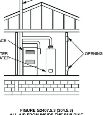
G2407.5.3 (304.5.3) Indoor opening size and location. Openings used to connect indoor spaces shall be sized and located in accordance with Sections G2407.5.3.1 and G2407.5.3.2 (see Figure G2407.5.3).
G2407.5.3.1 (304.5.3.1) Combining spaces on the
same story.Each opening shall have a minimum free
area of 1 square inch per 1,000 Btu/h (2,200 mm2/kW) of
the total input rating of all appliances in the space, but not less than 100 square inches (0.06 m2). One opening shall
commence within 12 inches (305 mm) of the top and one opening shall commence within 12 inches (305 mm) of the bottom of the enclosure. The minimum dimension of air openings shall be not less than 3 inches (76 mm). G2407.5.3.2 (304.5.3.2) Combining spaces in
differ-ent stories.The volumes of spaces in different stories
shall be considered as communicating spaces where such spaces are connected by one or more openings in doors or floors having a total minimum free area of 2 square inches per 1,000 Btu/h (4402 mm2/kW) of total input
G2407.6 (304.6) Outdoor combustion air.Outdoor combus-tion air shall be provided through opening(s) to the outdoors in accordance with Section G2407.6.1 or G2407.6.2. The mini-mum dimension of air openings shall be not less than 3 inches (76 mm).
G2407.6.1 (304.6.1) Two-permanent-openings method. Two permanent openings, one commencing within 12 inches (305 mm) of the top and one commencing within 12 inches (305 mm) of the bottom of the enclosure, shall be provided. The openings shall communicate directly, or by ducts, with the outdoors or spaces that freely communicate with the outdoors.
Where directly communicating with the outdoors, or where communicating with the outdoors through vertical ducts, each opening shall have a minimum free area of 1 square inch per 4,000 Btu/h (550 mm2/kW) of total input
rating of all appliances in the enclosure [see Figures G2407.6.1(1) and G2407.6.1(2)].
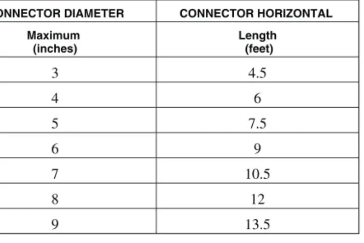
Where communicating with the outdoors through hori-zontal ducts, each opening shall have a minimum free area of not less than 1 square inch per 2,000 Btu/h (1,100 mm2/kW) of total input rating of all appliances in the
enclo-sure [see Figure G2407.6.1(3)].
G2407.6.2 (304.6.2) One-permanent-opening method. One permanent opening, commencing within 12 inches (305 mm) of the top of the enclosure, shall be provided. The appliance shall have clearances of at least 1 inch (25 mm) from the sides and back and 6 inches (152 mm) from the front of the appliance. The opening shall directly communi-cate with the outdoors or through a vertical or horizontal duct to the outdoors, or spaces that freely communicate with the outdoors (see Figure G2407.6.2) and shall have a mini-mum free area of 1 square inch per 3,000 Btu/h (734
mm2/kW) of the total input rating of all appliances located in
the enclosure and not less than the sum of the areas of all vent connectors in the space.
G2407.7 (304.7) Combination indoor and outdoor
combus-tion air.The use of a combination of indoor and outdoor
com-bustion air shall be in accordance with Sections G2407.7.1 through G2407.7.3.
G2407.7.1 (304.7.1) Indoor openings.Where used,
open-ings connecting the interior spaces shall comply with Sec-tion G2407.5.3.
G2407.7.2 (304.7.2) Outdoor opening location.Outdoor
opening(s) shall be located in accordance with Section G2407.6.
G2407.7.3 (304.7.3) Outdoor opening(s) size. The
out-door opening(s) size shall be calculated in accordance with the following:
1. The ratio of interior spaces shall be the available vol-ume of all communicating spaces divided by the required volume.
2. The outdoor size reduction factor shall be one minus the ratio of interior spaces.
3. The minimum size of outdoor opening(s) shall be the full size of outdoor opening(s) calculated in accor-dance with Section G2407.6, multiplied by the reduc-tion factor. The minimum dimension of air openings shall be not less than 3 inches (76 mm).
G2407.8 (304.8) Engineered installations.Engineered
com-bustion air installations shall provide an adequate supply of combustion, ventilation and dilution air and shall be approved. FIGURE G2407.5.3 (304.5.3)
ALL AIR FROM INSIDE THE BUILDING (see Section 2407.5.3)
FIGURE G2407.6.2 (304.6.2) SINGLE COMBUSTION AIR OPENING,
ALL AIR FROM OUTDOORS (see Section 2407.6.2)
For SI: 1 foot = 304.8 mm.
FIGURE G2407.6.1(2) [304.6.1(2)]
ALL AIR FROM OUTDOORS THROUGH VENTILATED ATTIC (see Section G2407.6.1)
FIGURE G2407.6.1(1) [304.6.1(1)]
ALL AIR FROM OUTDOORS—INLET AIR FROM VENTILATED
G2407.9 (304.9) Mechanical combustion air supply.Where all combustion air is provided by a mechanical air supply sys-tem, the combustion air shall be supplied from the outdoors at a rate not less than 0.35 cubic feet per minute per 1,000 Btu/h (0.034 m3/min per kW) of total input rating of all appliances
located within the space.
G2407.9.1 (304.9.1) Makeup air.Where exhaust fans are
installed, makeup air shall be provided to replace the exhausted air.
G2407.9.2 (304.9.2) Appliance interlock. Each of the
appliances served shall be interlocked with the mechanical air supply system to prevent main burner operation when the mechanical air supply system is not in operation.
G2407.9.3 (304.9.3) Combined combustion air and
ven-tilation air system.Where combustion air is provided by
the building’s mechanical ventilation system, the system shall provide the specified combustion air rate in addition to the required ventilation air.
G2407.10 (304.10) Louvers and grilles. The required size of
openings for combustion, ventilation and dilution air shall be based on the net free area of each opening. Where the free area through a design of louver, grille or screen is known, it shall be used in calculating the size opening required to provide the free area specified. Where the design and free area of louvers and grilles are not known, it shall be assumed that wood louvers will have 25-percent free area and metal louvers and grilles will have
75-percent free area. Screens shall have a mesh size not smaller than1/
4inch (6.4 mm). Nonmotorized louvers and grilles shall
be fixed in the open position. Motorized louvers shall be inter-locked with the appliance so that they are proven to be in the full open position prior to main burner ignition and during main burner operation. Means shall be provided to prevent the main burner from igniting if the louvers fail to open during burner start-up and to shut down the main burner if the louvers close during operation.
G2407.11 (304.11) Combustion air ducts.Combustion air
ducts shall comply with all of the following:
1. Ducts shall be constructed of galvanized steel complying with Chapter 16 or of a material having equivalent corro-sion resistance, strength and rigidity.
Exception: Within dwellings units, unobstructed
stud and joist spaces shall not be prohibited from con-veying combustion air, provided that not more than one required fireblock is removed.
2. Ducts shall terminate in an unobstructed space allowing free movement of combustion air to the appliances. 3. Ducts shall serve a single enclosure.
4. Ducts shall not serve both upper and lower combustion air openings where both such openings are used. The separation between ducts serving upper and lower com-FIGURE G2407.6.1(3) [304.6.1(3)]
ALL AIR FROM OUTDOORS (see Section G2407.6.1)
bustion air openings shall be maintained to the source of combustion air.
5. Ducts shall not be screened where terminating in an attic space.
6. Horizontal upper combustion air ducts shall not slope downward toward the source of combustion air. 7. The remaining space surrounding a chimney liner, gas
vent, special gas vent or plastic piping installed within a masonry, metal or factory-built chimney shall not be used to supply combustion air.
Exception: Direct-vent gas-fired appliances
designed for installation in a solid fuel-burning fire-place where installed in accordance with the manu-facturer’s instructions.
8. Combustion air intake openings located on the exterior of a building shall have the lowest side of such openings located not less than 12 inches (305 mm) vertically from the adjoining grade level.
G2407.12 (304.12) Protection from fumes and gases.Where
corrosive or flammable process fumes or gases, other than products of combustion, are present, means for the disposal of such fumes or gases shall be provided. Such fumes or gases include carbon monoxide, hydrogen sulfide, ammonia, chlo-rine and halogenated hydrocarbons.
In barbershops, beauty shops and other facilities where chemicals that generate corrosive or flammable products, such as aerosol sprays, are routinely used, nondirect vent-type appli-ances shall be located in a mechanical room separated or parti-tioned off from other areas with provisions for combustion air and dilution air from the outdoors. Direct-vent appliances shall be installed in accordance with the appliance manufacturer’s installation instructions.
SECTION G2408 (305) INSTALLATION
G2408.1 (305.1) General.Equipment and appliances shall be
installed as required by the terms of their approval, in accor-dance with the conditions of listing, the manufacturer’s instruc-tions and this code. Manufacturers’ installation instrucinstruc-tions shall be available on the job site at the time of inspection. Where a code provision is less restrictive than the conditions of the listing of the equipment or appliance or the manufacturer’s installation instructions, the conditions of the listing and the manufacturer’s installation instructions shall apply.
Unlisted appliances approved in accordance with Section 2404.3 shall be limited to uses recommended by the turer and shall be installed in accordance with the manufac-turer’s instructions, the provisions of this code and the requirements determined by the code official.
G2408.2 (305.3) Elevation of ignition source.Equipment and
appliances having an ignition source shall be elevated such that the source of ignition is not less than 18 inches (457 mm) above the floor in hazardous locations and public garages, private
garages, repair garages, motor fuel-dispensing facilities and parking garages. For the purpose of this section, rooms or spaces that are not part of the living space of a dwelling unit and that communicate directly with a private garage through open-ings shall be considered to be part of the private garage.
Exception:Elevation of the ignition source is not required
for appliances that are listed as flammable vapor ignition resistant.
G2408.3 (305.5) Private garages.Appliances located in
pri-vate garages shall be installed with a minimum clearance of 6 feet (1829 mm) above the floor.
Exception:The requirements of this section shall not apply
where the appliances are protected from motor vehicle impact and installed in accordance with Section G2408.2.
G2408.4 (305.7) Clearances from grade. Equipment and
appliances installed at grade level shall be supported on a level concrete slab or other approved material extending above adjoining grade or shall be suspended a minimum of 6 inches (152 mm) above adjoining grade.
G2408.5 (305.8) Clearances to combustible construction. Heat-producing equipment and appliances shall be installed to maintain the required clearances to combustible construction as specified in the listing and manufacturer’s instructions. Such clearances shall be reduced only in accordance with Section G2409. Clearances to combustibles shall include such consid-erations as door swing, drawer pull, overhead projections or shelving and window swing. Devices, such as door stops or limits and closers, shall not be used to provide the required clearances.
SECTION G2409 (308) CLEARANCE REDUCTION
G2409.1 (308.1) Scope.This section shall govern the
reduc-tion in required clearances to combustible materials and com-bustible assemblies for chimneys, vents, appliances, devices and equipment.
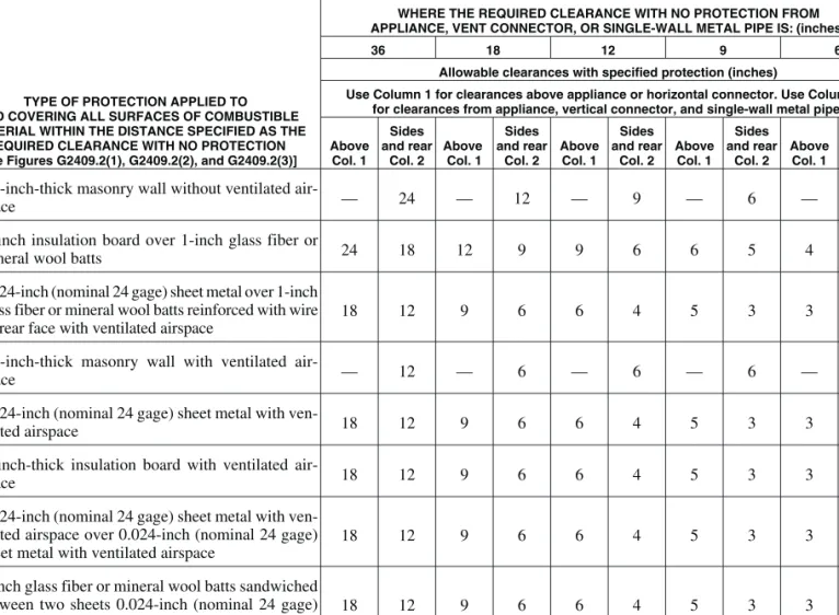
G2409.2 (308.2) Reduction table.The allowable clearance
reduction shall be based on one of the methods specified in Table G2409.2 or shall utilize an assembly listed for such appli-cation. Where required clearances are not listed in Table G2409.2, the reduced clearances shall be determined by linear interpolation between the distances listed in the table. Reduced clearances shall not be derived by extrapolation below the range of the table. The reduction of the required clearances to combustibles for listed and labeled appliances and equipment shall be in accordance with the requirements of this section except that such clearances shall not be reduced where reduc-tion is specifically prohibited by the terms of the appliance or equipment listing [see Figures G2409.2(1), G2409.2(2) and G2409.2(3)].
G2409.3 (308.3) Clearances for indoor air-conditioning
appliances.Clearance requirements for indoor
air-condition-ing appliances shall comply with Sections G2409.3.1 through G2409.3.5.
NOTES:
“A” equals the clearance with no protection.
“B” equals the reduced clearance permitted in accordance with Table G2409.2. The protection applied to the construction using combustible material shall extend far enough in each direction to make “C” equal to “A.”
FIGURE G2409.2(1) [308.2(1)]
EXTENT OF PROTECTION NECESSARY TO REDUCE CLEARANCES FROM GAS EQUIPMENT OR VENT CONNECTORS
For SI: 1 inch = 25.4 mm.
FIGURE G2409.2(2) [308.2(2)]
G2409.3.1 (308.3.1) Appliances installed in rooms that are large in comparison with the size of the appliances. Air-conditioning appliances installed in rooms that are large in comparison with the size of the appliance shall be installed with clearances in accordance with the manufac-turer’s instructions.
G2409.3.2 (308.3.2) Appliances installed in rooms that are not large in comparison with the size of the
appli-ances.Air-conditioning appliances installed in rooms that
are not large in comparison with the size of the appliance, such as alcoves and closets, shall be listed for such installa-tions and installed in accordance with the manufacturer’s instructions. Listed clearances shall not be reduced by the protection methods described in Table G2409.2, regardless of whether the enclosure is of combustible or noncombustible material.
G2409.3.3 (308.3.3) Clearance reduction.
Air-condition-ing appliances installed in rooms that are large in compari-son with the size of the appliance shall be permitted to be installed with reduced clearances to combustible material, provided the combustible material or appliance is protected as described in Table G2409.2.
G2409.3.4 (308.3.4) Plenum clearances.Where the
fur-nace plenum is adjacent to plaster on metal lath or noncombustible material attached to combustible material, the clearance shall be measured to the surface of the plaster or other noncombustible finish where the clearance speci-fied is 2 inches (51 mm) or less.
G2409.3.5 (308.3.5) Clearance from supply ducts. Air-conditioning appliances shall have the clearance from supply ducts within 3 feet (914 mm) of the furnace plenum be not less than that specified from the furnace plenum. Clearance is not necessary beyond this distance.
G2409.4 (308.4) Central heating boilers and furnaces. Clearance requirements for central-heating boilers and fur-naces shall comply with Sections G2409.4.1 through G2409.4.6. The clearance to these appliances shall not inter-fere with combustion air; draft hood clearance and relief; and accessibility for servicing.
G2409.4.1 (308.4.1) Appliances installed in rooms that are large in comparison with the size of the appliances. Central-heating furnaces and low-pressure boilers installed in rooms large in comparison with the size of the appliance shall be installed with clearances in accordance with the manufacturer’s instructions.
G2409.4.2 (308.4.2) Appliances installed in rooms that are not large in comparison with the size of the
appli-ances. Central-heating furnaces and low-pressure boilers
installed in rooms that are not large in comparison with the size of the appliance, such as alcoves and closets, shall be listed for such installations. Listed clearances shall not be reduced by the protection methods described in Table G2409.2 and illustrated in Figures G2409.2(1) through G2409.2(3), regardless of whether the enclosure is of com-bustible or noncomcom-bustible material.
G2409.4.3 (308.4.3) Clearance reduction.Central heating
furnaces and low-pressure boilers installed in rooms that are large in comparison with the size of the equipment shall be permitted to be installed with reduced clearances to com-bustible material provided the comcom-bustible material or equipment is protected as described in Table G2409.2.
G2409.4.4 (308.4.5) Plenum clearances.Where the
fur-nace plenum is adjacent to plaster on metal lath or noncombustible material attached to combustible material, the clearance shall be measured to the surface of the plaster or other noncombustible finish where the clearance speci-fied is 2 inches (51 mm) or less.
G2409.4.5 (308.4.6) Clearance from supply ducts.
Cen-tral-heating furnaces shall have the clearance from supply ducts within 3 feet (914 mm) of the furnace plenum be not less than that specified from the furnace plenum. No clear-ance is necessary beyond this distclear-ance.
G2409.4.6 (308.4.4) Clearance for servicing appliances. Front clearance shall be sufficient for servicing the burner and the furnace or boiler.
SECTION G2410 (309) ELECTRICAL
G2410.1 (309.1) Grounding.Gas piping shall not be used as a
grounding electrode.
G2410.2 (309.2) Connections. Electrical connections
between gas utilization equipment and the building wiring, including the grounding of the equipment, shall conform to Chapters 33 through 42.
For SI: 1 inch = 25.4 mm.
FIGURE G2409.2(3) [308.2(3)]
SECTION G2411 (310) ELECTRICAL BONDING
G2411.1 (310.1) Gas pipe bonding.Each above-ground portion
of a gas piping system that is likely to become energized shall be electrically continuous and bonded to an effective ground-fault current path. Gas piping shall be considered to be bonded where it is connected to appliances that are connected to the equipment grounding conductor of the circuit supplying that appliance.
CSST gas piping systems shall be bonded to the electrical service grounding electrode system at the point where the gas service piping enters the building. The bonding conductor size shall be not less than #6 AWG copper wire or equivalent.
SECTION G2412 (401) GENERAL
G2412.1 (401.1) Scope.This section shall govern the design,
installation, modification and maintenance of piping systems. The applicability of this code to piping systems extends from the point of delivery to the connections with the equipment and includes the design, materials, components, fabrication, assem-bly, installation, testing, inspection, operation and maintenance of such piping systems.
G2412.1.1 (401.1.1) Utility piping systems located
within buildings. Utility service piping located within
TABLE G2409.2 (308.2)a through k
REDUCTION OF CLEARANCES WITH SPECIFIED FORMS OF PROTECTION
TYPE OF PROTECTION APPLIED TO AND COVERING ALL SURFACES OF COMBUSTIBLE MATERIAL WITHIN THE DISTANCE SPECIFIED AS THE
REQUIRED CLEARANCE WITH NO PROTECTION [see Figures G2409.2(1), G2409.2(2), and G2409.2(3)]
WHERE THE REQUIRED CLEARANCE WITH NO PROTECTION FROM APPLIANCE, VENT CONNECTOR, OR SINGLE-WALL METAL PIPE IS: (inches)
36 18 12 9 6
Allowable clearances with specified protection (inches)
Use Column 1 for clearances above appliance or horizontal connector. Use Column 2 for clearances from appliance, vertical connector, and single-wall metal pipe. Above Col. 1 Sides and rear Col. 2 Above Col. 1 Sides and rear Col. 2 Above Col. 1 Sides and rear Col. 2 Above Col. 1 Sides and rear Col. 2 Above Col. 1 Sides and rear Col. 2 1. 31
/2-inch-thick masonry wall without ventilated
air-space — 24 — 12 — 9 — 6 — 5
2. 1
/2-inch insulation board over 1-inch glass fiber or
mineral wool batts 24 18 12 9 9 6 6 5 4 3
3. 0.024-inch (nominal 24 gage) sheet metal over 1-inch glass fiber or mineral wool batts reinforced with wire on rear face with ventilated airspace
18 12 9 6 6 4 5 3 3 3
4. 31
/2-inch-thick masonry wall with ventilated
air-space — 12 — 6 — 6 — 6 — 6
5. 0.024-inch (nominal 24 gage) sheet metal with
ven-tilated airspace 18 12 9 6 6 4 5 3 3 2
6. 1
/2-inch-thick insulation board with ventilated
air-space 18 12 9 6 6 4 5 3 3 3
7. 0.024-inch (nominal 24 gage) sheet metal with ven-tilated airspace over 0.024-inch (nominal 24 gage) sheet metal with ventilated airspace
18 12 9 6 6 4 5 3 3 3
8. 1-inch glass fiber or mineral wool batts sandwiched between two sheets 0.024-inch (nominal 24 gage) sheet metal with ventilated airspace
18 12 9 6 6 4 5 3 3 3
For SI: 1 inch = 25.4 mm, °C = [(°F - 32)/1.8], 1 pound per cubic foot = 16.02 kg/m3, 1 Btu per inch per square foot per hour per °F = 0.144 W/m2×K. a. Reduction of clearances from combustible materials shall not interfere with combustion air, draft hood clearance and relief, and accessibility of servicing. b. All clearances shall be measured from the outer surface of the combustible material to the nearest point on the surface of the appliance, disregarding any
interven-ing protection applied to the combustible material.
c. Spacers and ties shall be of noncombustible material. No spacer or tie shall be used directly opposite an appliance or connector.
d. For all clearance reduction systems using a ventilated airspace, adequate provision for air circulation shall be provided as described [see Figures G2409.2(2) and G2409.2(3)].
e. There shall be at least 1 inch between clearance reduction systems and combustible walls and ceilings for reduction systems using ventilated airspace. f. Where a wall protector is mounted on a single flat wall away from corners, it shall have a minimum 1-inch air gap. To provide air circulation, the bottom and top
edges, or only the side and top edges, or all edges shall be left open.
g. Mineral wool batts (blanket or board) shall have a minimum density of 8 pounds per cubic foot and a minimum melting point of 1500°F.
h. Insulation material used as part of a clearance reduction system shall have a thermal conductivity of 1.0 Btu per inch per square foot per hour per °F or less. i. There shall be at least 1 inch between the appliance and the protector. In no case shall the clearance between the appliance and the combustible surface be reduced
below that allowed in this table.
j. All clearances and thicknesses are minimum; larger clearances and thicknesses are acceptable.
buildings shall be installed in accordance with the structural safety and fire protection provisions of this code.
G2412.2 (401.2) Liquefied petroleum gas storage.The
stor-age system for liquefied petroleum gas shall be designed and installed in accordance with the International Fire Codeand NFPA 58.
G2412.3 (401.3) Modifications to existing systems.In
modi-fying or adding to existing piping systems, sizes shall be main-tained in accordance with this chapter.
G2412.4 (401.4) Additional appliances. Where an
addi-tional appliance is to be served, the existing piping shall be checked to determine if it has adequate capacity for all appli-ances served. If inadequate, the existing system shall be enlarged as required or separate piping of adequate capacity shall be provided.
G2412.5 (401.5) Identification. For other than steel pipe,
exposed piping shall be identified by a yellow label marked “Gas” in black letters. The marking shall be spaced at intervals not exceeding 5 feet (1524 mm). The marking shall not be required on pipe located in the same room as the equipment served.
G2412.6 (401.6) Interconnections. Where two or more
meters are installed on the same premises, but supply separate consumers, the piping systems shall not be interconnected on the outlet side of the meters.
G2412.7 (401.7) Piping meter identification. Piping from
multiple meter installations shall be marked with an approved permanent identification by the installer so that the piping sys-tem supplied by each meter is readily identifiable.
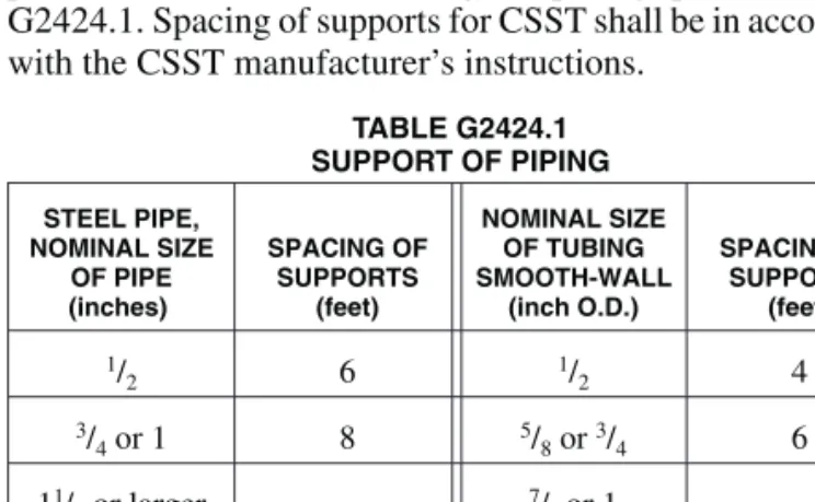
G2412.8 (401.8) Minimum sizes.All pipe utilized for the
installation, extension and alteration of any piping system shall be sized to supply the full number of outlets for the intended purpose and shall be sized in accordance with Sec-tion G2413.
SECTION G2413 (402) PIPE SIZING
G2413.1 (402.1) General considerations. Piping systems
shall be of such size and so installed as to provide a supply of gas sufficient to meet the maximum demand without undue loss of pressure between the point of delivery and the appli-ance.
G2413.2 (402.2) Maximum gas demand.The volume of gas
to be provided, in cubic feet per hour, shall be determined directly from the manufacturer’s input ratings of the appliances served. Where an input rating is not indicated, the gas supplier, appliance manufacturer or a qualified agency shall be con-tacted, or the rating from Table G2413.2 shall be used for esti-mating the volume of gas to be supplied.
The total connected hourly load shall be used as the basis for pipe sizing, assuming that all appliances could be operating at full capacity simultaneously. Where a diversity of load can be established, pipe sizing shall be permitted to be based on such loads.
G2413.3 (402.3) Sizing.Gas piping shall be sized in
accor-dance with one of the following:
1. Pipe sizing tables or sizing equations in accordance with Section G2413.4.
2. The sizing tables included in a listed piping system’s manufacturer’s installation instructions.
3. Other approved engineering methods. TABLE G2413.2 (402.2)
APPROXIMATE GAS INPUT FOR TYPICAL APPLIANCES
APPLIANCE
INPUT BTU/H (Approx.) Space Heating Units
Hydronic boiler
Single family 100,000
Multifamily, per unit 60,000
Warm-air furnace
Single family 100,000
Multifamily, per unit 60,000
Space and Water Heating Units
Hydronic boiler
Single family 120,000
Multifamily, per unit 75,000
Water Heating Appliances
Water heater, automatic instantaneous
Capacity at 2 gal./minute 142,800
Capacity at 4 gal./minute 285,000
Capacity at 6 gal./minute 428,400
Water heater, automatic storage, 30- to 40-gal. tank 35,000 Water heater, automatic storage, 50-gal. tank 50,000 Water heater, domestic, circulating or side-arm 35,000
Cooking Appliances
Built-in oven or broiler unit, domestic 25,000
Built-in top unit, domestic 40,000
Range, free-standing, domestic 65,000
Other Appliances
Barbecue 40,000
Clothes dryer, Type 1 (domestic) 35,000
Gas fireplace, direct vent 40,000
Gas light 2,500
Gas log 80,000
Refrigerator 3,000
For SI: 1 British thermal unit per hour = 0.293 W, 1 gallon = 3.785 L, 1 gallon per minute = 3.785 L/m.