Change management in concurrent engineering
from a parameter perspective
Kamel Rouibah
a, Kevin R. Caskey
b,* aCollege of Business Administration, Kuwait University, Kuwait b
School of Business Administration, State University of New York, SBB Room 127, 75 S. Manheim Blvd. Suite 9, New Paltz, NY 12561-2443, USA
Received 29 June 2001; accepted 4 October 2002
Abstract
Information and communication technologies (ICT) have altered the balance of cost between activities within a firm and activities between firms. Easier co-operation allows companies to focus on their core strengths, while forming relations with other firms to supply the other needed skills to bring a product to market. Design, in one firm or in a consortium, is iterative and does require change. The ability of companies to better manage engineering changes (ECs) during product development can decrease cost, shorten development time, and produce higher quality products.
This paper concerns engineering change management (ECM) when product development involves more than one company. A review of ECM related papers finds a lack of those that address multi-company design efforts. This approach is based upon recent work in collaborative engineering, which uses elementary engineering decisions, captured as parameters, to drive the collaboration. The relationship between parameters determines the involvement of suppliers and engineering partners. This allows design partners to be informed early as to the impact of design changes. We describe the use of this approach in simultaneous ECM, its implementation within a product data management (PDM) system, and initial test results. We term this approach as ’intelligent’ because it is based upon knowledge captured in the design process itself.
#2002 Elsevier Science B.V. All rights reserved.
Keywords:Engineering change management; Product development; Design management; Concurrent engineering; Virtual enterprise
1. Introduction
Information and communication technologies (ICT) have altered the equilibrium of costs between performing activities within a firm and co-operating with other firms to obtain needed services. Many product development firms have found this equili-brium shift allows greater co-operation between firms in the design of new products.
Firms have also found that product development efforts benefit from the early involvement of many functions besides product design. Among these other functions can be representatives of other engineering disciplines, manufacturing or marketing. This approach to design has been called simultaneous or concurrent engineering (e.g.[1]).
While organisational aspects of change manage-ment have received much attention, relatively little research has addressed engineering change (EC) sup-port in manufacturing companies related to product development [2–4].
*Corresponding author.
E-mail address:[email protected] (K.R. Caskey).
0166-3615/02/$ – see front matter#2002 Elsevier Science B.V. All rights reserved. PII: S 0 1 6 6 - 3 6 1 5 ( 0 2 ) 0 0 1 3 8 - 0
of recent and relevant literature dealing with ECM.
Section 4presents requirements for advanced ECM in a multi-partner relationship.Section 5introduces a new approach to address the extensions identified in the review of current approaches and to fulfil the new requirements.Section 6presents initial implementation and test results. The last section summarises the key elements of the paper and identifies new perspectives.
2. The need for distributed engineering change management
Product development is increasingly performed in a distributed environment. This requires distributed engineering change management. Product develop-ment is also an iterative process. Making design decisions early has benefits but often requires mod-ifications or engineering changes (ECs) [5]. These may arise in order to satisfy design constraints and objectives [6], to ease manufacture, to eliminate a design conflict, or to deal with an emerging product requirement (for example, requested by marketing or the customer). Among the requirements for successful multi-firm concurrent design are:
Close and early co-operation between companies.
Concurrent engineering, (close early co-operation between disciplines).
Fast response to required engineering changes.
Support of information and technology.
Firms may co-operate with suppliers and engineering partners for several reasons. They may find it quicker or more cost effective to bring in a needed skill rather than
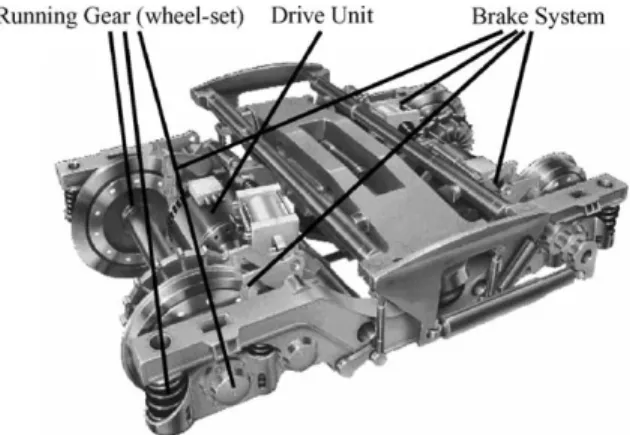
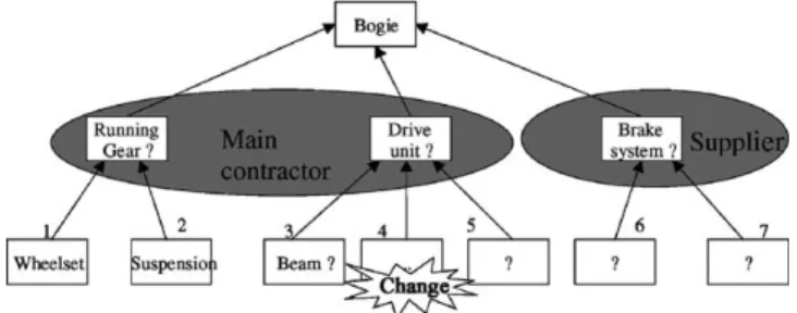
develop the capability in-house, or they may seek partners in order to respond quickly to the changing needs of customers [7]. When these partnerships are of short or intermediate term duration they may be referred to as virtual enterprises (e.g.[8,9]). For exam-ple, designing passenger railcar ‘‘bogies’’, shown in
Fig. 1, requires the co-operation of many engineers from several companies (Fig. 2).
The effort may be co-ordinated by the firm respon-sible for component assembly, while others supply major components (such as the running gear, drive unit and brake system). Each participant brings only its core competency while relying on the others to com-plete the co-operative effort. The rail–car bogie is the test subject presented inSection 6.
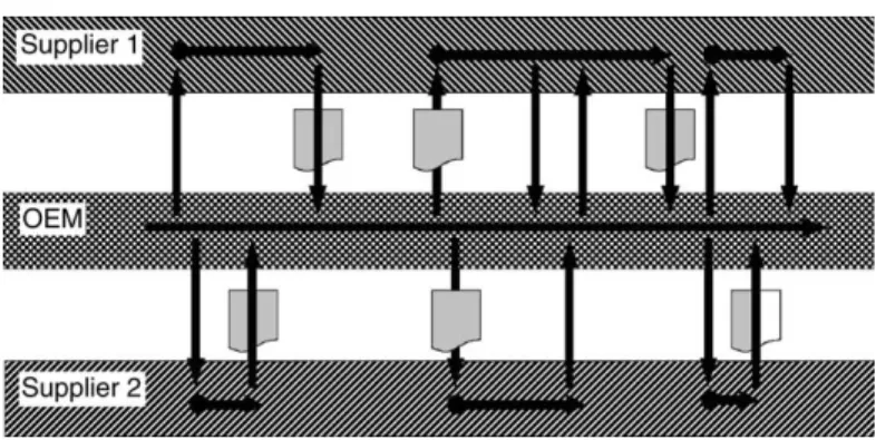
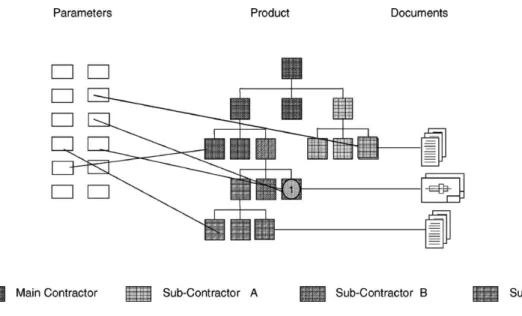
Producing product to customer order can follow several strategies, such as make-to-order, assemble-to-order, and engineer-to-order [7]. Make-to-order involves combining standard parts into a finished product. As the parts already exist, the engineering effort is in choosing and documenting the combina-tion. Engineer-to-order (such as designing the above bogie), the focus of this paper, usually requires con-siderably more design effort. Each product is new and carries the implication of a large number of design choices. In a concurrent environment, these decisions may be made early using approximate values and then tightened or changed later (e.g.[10]). This iterative process will often lead to ECs. Co-operation between companies in engineer-to-order requires exchanging and maintaining the validity of a large engineering data set. This is especially important when engineer-ing changes are in process.Fig. 2shows documents
Fig. 1. Bogie, an example of complex product.
1Workflow Management for Simultaneous Engineering
Net-works (SIMNET). SIMNET was a project funded by the Commission of the European Communities under the ESPRIT programme (EP 26780), see Acknowledgement for list of participants.
flowing between the original equipment manufacturer (OEM) and two suppliers (vertical arrows) as the design evolves (horizontal arrows).
Besides co-operating between companies, the design effort should also support functions or disciplines working concurrently. Traditional sequential product development is time-consuming and can lead to a considerable amount of redesign. As different engineer-ing teams perform their tasks in isolation, they detect omissions in earlier designs, which lead to many ECs. For example, once the designer completes a set of drawings, manufacturing engineers may need to rede-sign the parts for ease of manufacture. Concurrent engineering can, therefore, avoid the difficulties of sequential design and can react more quickly to external and internal events[1].
While communication and co-operation may reduce the need to alter engineering decisions, it will not be eliminated. Required engineering changes should be responded to quickly, completely (deal with all impacts), and efficiently (without undue effort). ECM meeting these goals is the focus of this paper.
By EC we refer to changes or modifications in form, representation, design, material, dimensions, func-tions, etc. of a product or component after an initial engineering decision has been made (e.g.[3,11]). ECs play an important role in product development and contribute to improving products. To eliminate them entirely is both undesirable and unrealistic [12]. Depending on when in the design process they occur, we can specify three kinds of ECs:
ECs during initial design. These can often occur early in the design and be small modifications with
minimal impact. The closer these changes occur to the end of the initial design effort the greater the potential impact.
ECs after the initial design period. Once a design has been completed, it will be approved and then enter production. Changes after production has begun generally cause greater disruption. In many environ-ments, the design must be approved by many orga-nisations or even government agencies (such as governmental aviation agencies in the case of air-craft). As changes after the design has been released and approved may alter what has been approved, these often require strict management procedures.
ECs during the major reconstruction of a product. We refer to this as development of versions and variants.
We focus on the first category, as this is what was addressed by the test-case.
Several strategies are widely used in product devel-opment to minimise the impact of the first and second types of ECs:
Avoid changeas much as possible by spending more engineering time on the first release[12].
Make changes as early as possible in the design process, i.e. [2,3,6]. Once design resources have been spent, ECs become more expensive and harder to include the later they are implemented.
Ease the processingof changes that do occur. A number of techniques and tools exist to support the first two strategies, such as quality function deployment. Even though these techniques are con-sidered effective to decrease ECs early in design, some
product in a planned or systematic fashion. While the product can be under development, to be delivered or already delivered, more formal methods generally refer to after the design is released. This process encompasses the emergence of a need for a change, the request for a change, the management approval of the change, implementation, and documentation where all impacted product data2have been updated. Formal ECM usually consists of two major parts (adapted from [13]). An engineering change request (ECR) drives request and approval. An engineering change order (ECO) drives change realisation. Both ECR and ECO are usually formal documents notifying selected persons of proposed, pending, or accom-plished changes. In many industries (such as aero-space), this process and often the resulting change must be approved by regulators.
The following section reviews recent literature in order to show the importance of the subject and reveal issues yet to be addressed.
3. Other ECM efforts
Our prime objectives in reviewing other efforts were to identify whether previous research has addressed ECM in multi-partner relationships, and to determine whether the approaches described were limited in their ability to support these efforts. We classified recent papers that deal with ECM into four classes (Table 1).
Our review of the above research and other work in the area leads to the following insights.
3.1. ECM is an important area of research
The previous studies (including survey research) show that much attention has been paid to the subject
of ECM by researchers (e.g. [11,14]), industry (e.g. [2,3,15]) and consultants (e.g. [13,16]). For example, Maull et al.[17]indicated that companies that identified ECM as a major problem were the most advanced in developing their manufacturing processes.
3.2. The cost and time needed for ECM demands action
Industrial case studies conducted recently in man-ufacturing industries[3,17–19], have reported that EC is a serious problem within manufacturing. Many report ECM to be time-consuming (from requesting an EC to implementation) and costly. For example, Huang and Mak[3]have found an average of about 65 active ECs in the 100 UK companies surveyed. This is consistent with Maull et al. [17] and Boznak [18]. Boznak reported the annual EC administrative proces-sing cost in surveyed companies (from small firms to Fortune 500 companies) ranged from US$ 3.4 million to US$ 7.7 million. Maull et al.[17]found that ECs may incur a cost up to 10% of annual turnover. Watts
[20]discovered that it requires in average of 40 days to discover an EC, 40 days to process and approve an EC, and 40 days to implement it. EC activities consume one-third to one-half of engineering capacity [2,21], and represent 20–50% of tool cost. Clark and Fujimoto
[12]report that 20–40% of die development costs in vehicle development are caused by EC.
Soderberg[21], Reidelbach[22], Balcerak and Dale[26], Saeed et al.
[35], Pikosz and Malmqvist[15], Terwiesch and Loch[2]
Methods and frameworks for implementation
Harhalakis[25], McKnight and Jackson[36], Reidelbach[22], Huang and Mak[11], MIL-STD-973[37]
Tools & IT solutions Krishnamurthy and Law[23], Huang and Mak[11], Huang et al.[4]
3.3. Few ECM systems address multi-company design
Managing engineering changes is time-consuming and difficult within a single company. This becomes much more difficult if the product definition is per-formed across-company borders. While there are many frameworks to support ECM within single companies, few address ECM between companies, even though many papers talk about early supplier integration in product design. Reidelbach[22]has proposed a frame-work to reduce the negative impact of EC. Huang and Mak[3]have reported that almost all surveyed com-panies (about 90%) agreed that a well-structured pro-cedure was one of the most significant elements of a formal ECM system. Huang et al.[4]have proposed both a framework and a system (web-based) to assess the impact of ECs on the various aspects of the business across a manufacturing company. This prototype could be used in a multi-firm environment.
3.4. Current ECM computer systems tend to be (virtual) paper based
Almost all authors consider the use of information systems useful to support ECM. A few papers address computer-based ECM. They tend to be focused on specific applications, industries, and products. Among widely described ECM systems are the activities of Krishnamurthy and Law[23], Huang and Mak[3,11]
and Huang et al.[4]. The web-based system to track design changes of Huang et al. [4] consists of cen-tralising and displaying the EC data, and identifying the causes and effects, with numerical ratings to indicate the occurrence of the cause and severity of the effect, respectively. While this is computer sup-ported, it is based upon electronic forms.
Existing computer systems for ECM, developed in-house (stand-alone) or available commercially, have been categorised by Huang and Mak[11] into three types:
1. Basic applications such as using word processors used to prepare EC documents and spreadsheets to record EC data.
2. In-house small systems, such as specific databases, that are especially developed to support basic EC activities including requesting and recording ECs.
3. Product data management (PDM) and enterprise resources planning (ERP) systems that provide more comprehensive functionality than just mana-ging ECs. These systems ease communication and data management, and implement ECM as an additional capability.
Kidd and Thompson[19]report that existing systems are often inefficient and slow. For example, they point out that only one person can review change documenta-tion at a time and the review cycle can be stopped by bottlenecks.
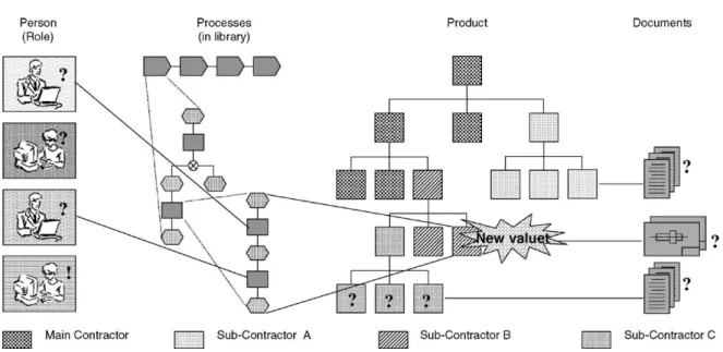
Few of these systems are actually in use. The case study of Pikosz and Malmqvist[15]has revealed that usage of computer systems to support ECM is rather low in the three Swedish companies they studied. The survey research of Huang and Mak [3]gives insight about systems in use. They found that ECM activities were still done manually and only a few companies used systems. They found only two UK companies out of 100 used computers to support the ECM process and one-third used systems to record and track ECs. While the potential benefits of PDM systems are significant[24], Huang and Mak [3]also found less that one-third of their surveyed companies reported using PDM systems. We can propose a number of reasons for this lack of use. First, the lack of use could be that these systems lack a link between the actual product data and the engineering processes (Fig. 3).
Second, current functionality only provides support for the document-based administration of engineering change processing, i.e. the formal activities related to the change. Technical activities such as the verifica-tion of the change’s impact within the product struc-ture and the later redesign of the product components are either supported insufficiently or not at all. While the system of Huang et al. [4] is web-based and overcomes the limits of paper, it does not allow concurrent ECM management and currently offers support for only one company.
Systems also lack support to propagate change in an intelligent manner. A change in one component of a product causes changes in other components and documents, and therefore affects the work of many people. However, few papers report the impact of this change propagation, termed the snowball effect by Terwiesch and Loch[2]. We found that authors often suggest linking ECM to bills of materials (BoM)
(components, parts) ([2,17,25,26], or to documents (MIL-STD 973). For example, Harhalakis [25] at Ingersoll Rand found that 98% of ECs are related to BoM and contractual changes in their make-to-order activities. However, the authors did not report if their suggestions to link ECs to BoM or to documents were implemented. In addition, we did not find any paper that showed how related objects (such as docu-ments or components), affected by ECs, are handled in an intelligent manner (a manner based upon knowl-edge of the underlying relationships) so that ECM is performed efficiently. Specifically, papers that propa-gate the change through the components and docu-ments in a structured manner are lacking.
The managerial importance of ECM, the long lead time, the disproportionate amount of waiting time in the ECM life cycle together with the scarcity of previous academic work related to ECM in a multi-company design setting motivate our research. More specifically, we attempt to provide information in an intelligent manner early to the right suppliers and co-designers (companies in a multi-partner relationship) on the impact of EC. While speed is important, better control can also lower cost and improve quality.
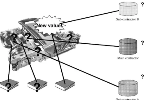
Each change of the product or its corresponding documents causes a change in the product configuration (Fig. 4). A change in one component can cascade through other parts and documents. Every time a part
revision is proposed, it must be linked to the correct parts, documents, and individuals impacted. An effec-tive approach for ECM should in the case of a desired or necessary product modification provide functionality that:
Tracks the change’s impact on the elements of the product structure.
Identifies the people to be informed, both within the company and across-company borders.
Determines a reasonable sequence for informing the people identified.
Executes an approval and release workflow (order of activities) with the participation of all persons involved or affected by the change.
The following section will combine these findings with the requirements for distributed engineering change management introduced inSection 2. We will present an updated list of requirements to support engineering change when collaborative engineering involves several companies.
4. Requirements for collaborative, multi-company ECM
As the design activities themselves are concurrent, we suggest performing EC activities in a concurrent manner. While several aspects of ECM are important,
this paper will investigate ECM from a co-operation point of view. This co-operation has several require-ments. The following sub-section will elaborate these requirements.
4.1. Support communication
ECM requires extensive communications between many people within a company and between compa-nies. Almost all ECM related papers agree that com-munication across functional lines can help avoid many problems (see[26]). Terwiesch and Loch[2]suggest extending this inclusive communication beyond func-tional departments to include suppliers in order to deal with interfacing components affected by the change. Recommendations from research into communication across functional boundaries (such as between market-ing and R&D) apply also to improvmarket-ing ECM (e.g.
[27,28]). They recommend frequent contact to enhance communication, and having clear procedures to enable better and easier communication between people involved in meeting the order requirements. Clear communication procedures require establishing clear roles between participants involved in the process. On the other hand, lack of communication leads to a poor process. For example, the survey of Huang and Mak[3]reported that the two most significant barriers
(four–fifths of the surveyed manufacturing companies) to effective ECM were ‘‘poor communication’’, and ‘‘problems are discovered too late resulting in panic and leading to quick fix solutions’’.
4.2. Involve all relevant parties
ECM in a collaborative, multi-company setting requires collaboration among different departments and suppliers. ECM is quicker and less prone to error when the process is performed concurrently and data are transparent to all concerned parties. Engineering changes affect downstream activities with regard to product and processes, and therefore work teams (cross department and inter-company). These teams are there-fore involved in managing ECs. The departments most involved in ECM are design, industrial and production engineering[3]. However, these co-operations extend to cover others from design to after-sales, production, and manufacturing. Terwiesch and Loch[2]found in their case study that ECM involves 4–7 departments (project team, engineering, functional engineering of one or more interfacing components, quality management, production planning, finance/accounting, purchasing and prototyping). ECM has strong implications to all functions of a company and its suppliers, either as resources or as those impacted.
4.3. Work toward consensus
A change can be started from departments other than engineering. Many departments are affected when documents or specifications have to be changed. The change may be difficult to handle since the goals of people involved are different. The goal of engineer-ing is to perform a certain function in the best way possible, whereas the goal of manufacturing might be to assemble in a short time, and cutting material costs might be the main objective for purchasing. Therefore, the change process requires the approval of all involved persons who may be affected by the change. The EC process may lead to several negotia-tions in order to arrive at a consensus.
4.4. Control the process
The process of controlling ECM is complex[29]. Interdependent activities require co-ordination. This ensures the collaborative actions of participants to achieve the desired result as efficiently as possible. Reidelbach[22]stresses the importance of co-ordinat-ing EC efforts within a committee. This committee must assess, implement, and manage EC methods and procedures. For instance, three out of four companies surveyed by Huang and Mak[3]reported that appoint-ing an EC co-ordinator and establishappoint-ing an EC board or committee are necessary to carry out ECM effi-ciently.
4.5. Identify the scope of impact
One factor that influences ECM speed and quality is change propagation. This is the result of couplings between the component that is modified and interfacing
components or development activities. The stronger the couplings between components, the more likely the change in one part of the system will create a change in another part. Here, the essential issue is the relationship between objects (parts, components, parameters, etc.). The related objects may cause other changes and thus, changes in the whole product. There are three groups of couplings (seeFig. 5above):
Between a product component and its correspond-ing manufacturcorrespond-ing process.
Between a product component and other compo-nents (within the same company).
Between a product component and other compo-nents in other partners (suppliers).
In addition, the larger the changes made, the more complex the analysis. A system that has already captured these couplings will greatly facilitate ECM. Because of the large amount of relations and the resulting change propagation, a procedure that can handle such complex relationships will be helpful to conduct ECM with efficiency. The approach presented in the next section captures relationships by logging basic engineering decisions. These relationships can then identify the above couplings.
The next section describes an approach to engineer-ing change management that supports the five require-ments just described. This will be based upon parameters, as we will show in the following sections.
5. A parameter-based approach to intelligent ECM
The approach to engineering change management (ECM) discussed in this paper is an extension of
parameter-based concurrent engineering[30,31]. At its most basic level, engineering decision-making deals with determining engineering values. Para-meter-based concurrent engineering links engineer-ing activity through decisions about basic engi-neering attributes, termed here as parameters. The relationships between these values, and the people working with them capture the evolution of design project. We use the term intelligent ECM because it is based upon and exploits the knowledge of these relationships originally captured during initial pro-duct design.
This section will first describe the basics of para-meter-based concurrent engineering and then its adaptation for ECM in a multi-firm setting. The intent of the next subsection is limited to discussion of topics needed to understand the use of this approach in ECM. These topics include: parameter evolution, the people involved in the process, and the network that captures the relationships. A more complete description of parameter-based concurrent engineer-ing can be found in Schmitt[31] and Rouibah and Caskey[32].
5.1. Overview of the parameter-based approach
We adopt an approach to the co-ordination of engineering activities in the engineer-to-order envir-onment based upon parameters (see [30] and [32]). This approach was implemented and tested within the SIMNET project. Interviews with engineers at the main contractor with this project, Siemens SGP Trans-port Systems, found the parameter view consistent with the way engineers view their work. They see it as making engineering decisions, not as creating docu-ments or as following processes. These engineering decisions change or determine engineering variables. We refer to the most elementary of these engineering variables as parameters. Parameters represent the specific circumstances in a given engineering situa-tion. They can refer to dimensions as well as forces and movements. During collaborative design, as dif-ferent people decide on parameter values, capturing the relationship between parameters consequently specifies the relationship between the decision-makers. When these people work in the co-operating companies, the relationship between parameters cap-tures the required interaction of a main contractor with
its suppliers and engineering partners. Parameters can then be used as a platform for cross-company com-munication, linking processes, people, and product items (Fig. 9 and later section will describe this in greater detail).
Before discussing ECM using an instantiated parameter network, we will first introduce parameter evolution, the people involved in the process, and the resulting parameter network.
5.1.1. Parameter value evolution
Concurrent engineering is an iterative process. The evolution of parameters can capture and guide this process. The evolution of parameter values reflects both the interaction and acceptance among the design team, and the perceived certainty, or maturity, of the parameter value itself. We refer to the state of design team interaction as parameter
status, and the degree of parameter value certainty asmaturity.
Parameter values and their relationships represent design specification. For example, engineers may agree to a specific maximum target speed for an aircraft or a specific dimension for a part.
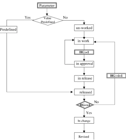
Maturity level captures the certainty the design team has in a parameter’s value. During product design, engineering data exist in multiple levels of maturity, within different departments and within different companies when product development involves more that one company. The text case dis-cussed below quantified maturity with numerical hardness grades from HG1 to HG5 (see,Fig. 6). These grades reflect value certainty. For example, HG1 may relate to a parameter having an estimated value with an open range, while HG5 relates to an exact value with final tolerances. The evolution of a parameter value through hardness grades controls the design process.
Parameter status is the collaborative process of assigning values to parameters moves through several states. Fig. 6 displays six of these relating to initial design (predefined,un-worked,in work,in approval,
in release,released), and two relating to engineering change (in changeandrevised).
The above discusses the evolution of a single parameter. However, it is the interaction of the entire set of parameters that drives design and change man-agement. Capturing the relationships will be discussed
in the parameter network (Section 5.2). The task of identifying the parameter set will be reviewed when the use of the network is introduced.
Several people can be involved in the evolution of a parameter and in its change. The next section will introduce these people.
5.1.2. Tasks and user categories
As stated above, current PDM systems do not capture the link between product data and the engi-neering processes during which the persons generate, change, review and release these data. The parameter-based approach introduces the notion of roles and establishes links by assigning roles related to para-meter processing to the engineers involved. These roles then have associated tasks connected to the evolution of parameter values.
Rouibah and Caskey [32] present five categories (roles) that a user can assume regarding a certain parameter:co-ordinator,collaborator,reviewer,
sub-scriber and supervisor. Users assuming these roles may come from any of the companies participating in satisfying a customer demand.
Theco-ordinatorof a parameter is a person tech-nically responsible for it and drives its elaboration or evolution.
Collaboratorsare directly involved in the parameter elaboration, for example engineers from different partners working on the same interface parameter, but having a different view on it.
Reviewersincludes all users that must be consulted about a parameter, but do not determine it, such as a production planner who must check whether a shaft with a certain length can be produced in-house or not.
Subscriberscan be persons wishing to be informed about the development of a certain parameter without being assigned to a category that works on it.
Thesupervisoris responsible for releasing a para-meter.
5.2. Parameter networks
Parameters often share complex relationships. These relationships might be represented by mathe-matical equations (such asEqs. (1) and (2)), diagrams, or tables. The capture of parameter relations during concurrent design results in a parameter network.
Eqs. (1) and (2) show that parameters may have a direct or indirect relationship:
max axle diam¼fðmax axle load;bear dist;
track gauge; axle materialÞ (1) wheel motor dist
¼fðgear transm ratio;wheel diam worn;
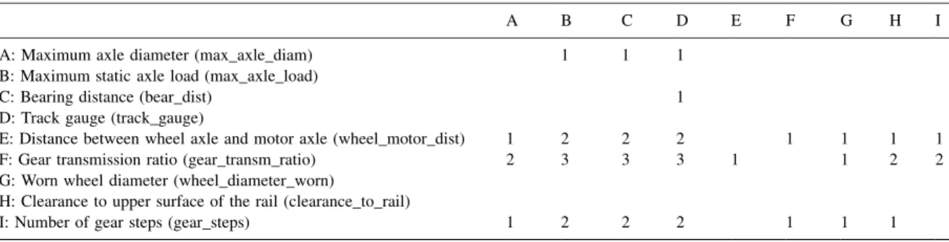
max axle diam;clearance to rail;gear stepsÞ (2) The parameters inEq. (1)are directly related, while max_axle_load and gear_steps are indirectly related throughEq. (2). An example of relationships repre-sented in tabular form is shown inTable 2. The smaller the number in the table, the closer relationship is between the parameter in the row and in the column (1 is direct, 2 is 1st order indirect, etc.).
Table 2does not show all the relationships within a design project, just as there will be more equations than two. The relationships among parameters are captured in the design process (described more completely in[32]). The most important para-meters will often be identified at the start of a design project. The relations between these parameters can be then defined explicitly or by adapting those identified in previous, similar projects. During the design project, more parameters will be identified,
relationships will be captured, and modified. Instan-tiating parameters and their relationships results in the creation and further definition of a logged para-meter network.
The next section focuses on the use of the logged parameter network to facilitate ECM.
5.3. Using the parameter network to support ECM
The capture of parameter relations during concur-rent design results in a parameter network. This net-work can be used to support an intelligent ECM process that will not only satisfy the requirements of Section 4but also be fairly easy. While easy is a subjective term, as the process is an extension of the method used to create the network (parameter-based concurrent engineering), we believe it is appropriate. In this context, change means modification of para-meter values motivated by one of several reasons (see
Section 2). For example, the customer changing the intended operating range of an aircraft may motivate
increasing fuel capacity.
The need for change can emerge during the initial design, after a design has been approved, or once a product is in production. Engineering change after design approval or once production has begun is often more formal. In some industries (such as the aerospace industry) it may often require strict documentation and even re-approval. Changes requested long after initial design might also find that the original participants are no longer available or even that the consortium is no longer together. For these reasons, and because the test case discussed below focused on the design phase, we
Table 2
Example of parameter relationships
A B C D E F G H I
A: Maximum axle diameter (max_axle_diam) 1 1 1
B: Maximum static axle load (max_axle_load)
C: Bearing distance (bear_dist) 1
D: Track gauge (track_gauge)
E: Distance between wheel axle and motor axle (wheel_motor_dist) 1 2 2 2 1 1 1 1
F: Gear transmission ratio (gear_transm_ratio) 2 3 3 3 1 1 2 2
G: Worn wheel diameter (wheel_diameter_worn)
H: Clearance to upper surface of the rail (clearance_to_rail)
(2) Identification of parameters to be changed. (3) Change control of the parameter. This consists of
propagating the change through the identified parameters and to ensuring that the change is being properly implemented.
(4) Audit of parameters affected by the change. This consists of mapping the change propagation by reporting the change to others who may have interest.
(5) Recording the change for historical reference. As parameter-based engineering change manage-ment uses knowledge gained in parameter-based con-current engineering, we will first describe aspects of the design process that collect the knowledge that will be used in ECM.
5.3.1. Collecting the knowledge later used in parameter-based ECM
The parameter network used to support engineering change management is created as part of the concur-rent engineering design process. The knowledge
con-system parameters and interface parameters span company boarders. This parameter definition can be presented as a checklist and created, for example, with the aid of similar past projects. This is intended to be a starting place, not to be an exhaustive list. At this point just the parameters are listed, not their relationships.
Step 2: Identification of user categories and assign-ment of people to user categories. The people involved in the cross-company engineering activities are then assigned directly to the parameters. Once again, this may be partially based upon earlier pro-jects. However, the same parameter in different projects may be defined by different roles in different companies. These roles are represented by the five user categories (seeSection 5.1.2).
Step 3: Identifying predefined parameters. The final values of some parameters may be agreed in advance. For example, the customer may specify performance requirements or specific dimensions. As these are not subject to evolution during design
Table 3
Dependencies between parameters and product structure items related to the bogie example
Dependencies between product structure items/parameters Max_axle_diam Max_axle_load Bear_dist Track_gauge Wheel_motor_dist Gear_transm_ratio Wheel_diameter_worn Clearance_to_rail Gear_steps
1. Brake equipment A
1.1. Friction brake
1.1.1. Wheel disc brake complete
1.1.1.1. Brakes pliers A A A A
1.1.1.2. Spring-brake cylinder A A A
1.1.1.3. Hose line
1.2. Magnetic rail brake A A
2. Traction drive unit A
2.1. Motor unit complete A A A
2.1.1. Motor fixed to bogie frame
2.1.1.1. Motor unit A A A A
2.1.1.2. Decoupling of structure borne noise
2.2. Clutch motor-gearbox A A
2.3. Gear unit complete A A A
2.3.1. Gear unit riding on axle
2.3.1.1. Gear unit A A A A 2.3.1.2. Torque bracket A: available. Rouibah, K.R. Caske y /Computers in Industry 50 (2003) 15 – 34 27
start-up is finished. However, the start-up phase continues in each individual company.
Step 4: Linking of parameters with product items. Once the previous steps are achieved, each company must now assign users to its roles (see step 2). Once this activity is done, the next step consists of linking parameters to product items (see,Fig. 7). One way to do is to take an existing or draft product structure.
Table 3shows an example of parameters linked to product structure items (the table is not meant to show all parameters).
While the design teams will attempt to be thor-ough, there is no expectation that they will have captured all the relevant parameters at this point. More will be identified and added during design, as stated in step 5.
Step 5: Creation of values for the remaining para-meters. The design process will identify additional values that need to be specified. This causes new parameters to be introduced.
Step 6: Parameter approval and release. Once all parameters reach the highest level of maturity, the design can be released.
Reaching design release also results in an instantiated parameter network related to the design of a specific product. However, during design the
ECM step is to identify the parameters that must be changed. This requires propagating the change impact through the network.
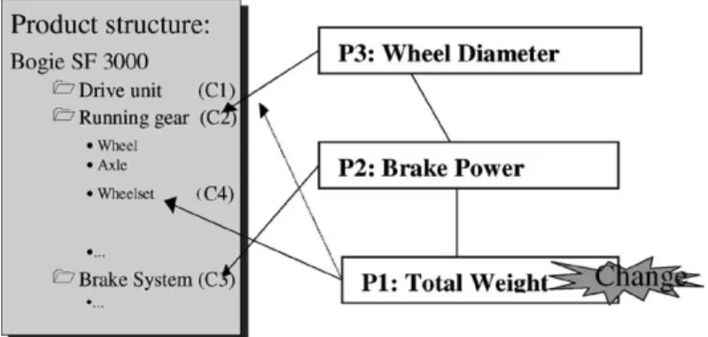
To illustrate propagation, we can refer to the exam-ple where a bogie needs to support an increase in the total weight of the train to satisfy an external requirement (such as including an air conditioning system) (seeFig. 8).
The ‘‘total weight’’ (parameterP1) affects both the
bogie components ‘‘drive unit’’ (C1) and ‘‘running
gear’’ (C2). P1 also affects the parameter ‘‘brake
power’’ (P2) that influences indirectly the ‘‘brake
system’’ (C3). In addition, P2 affects the parameter
‘‘wheel diameter’’ (P3) that affects max_axle_diam
and other related parameters (seeTable 3). Thus, by using indirect relationships,P1affects bothP3and the
sub-component ‘‘wheelset’’ (C4). Therefore,
engi-neers working with components C1, C2, and C4 (at
the prime contractor), andC3(at the brake supplier) as
well as others working with parametersP1,P2, andP3
should be automatically informed. Documents asso-ciated with the three componentsC1,C2, andC3must
be updated. After that, each company has to propagate the change within its parameter network.
The path to trace the related parameters is complex when a need for change is identified. Parameters often
are related to several others to different degrees (see
Table 2). There will often be several relations to be checked. However, we may believe that the closer the relationship (indicated, for example, by the entries in
Table 2) the more directly a change in one parameter impacts another. Therefore, we can set the following rule for parameter-based ECM: handle parameters that have 1st degree relationships and then move on to less directly related parameters. Therefore, the verification sequence is: finish all degree 1, finish all degree 2,. . ., finish all degreen.
The following steps describe an ECM procedure that reflects the concepts of the previous paragraph. Once the external request for a change has been received, the objective is to cope successfully with change propaga-tion through the design by means of step-by-step para-meter identification and the involvement of the required people (using the above role descriptions, these are co-ordinators and collaborators).
Step 1: Identification of the parameters requiring change and notification. Any person involved in the multi-company engineering process may request the change of a parameter value. Change requests are usually communicated in a parameter-based way with a title including a short description of the change. Examples are:the engine power needs to be increased or the shaft diameter is not suffi-cient. The parameter to be changed then automati-cally becomes the starting point for all further considerations. Afterwards, only the persons (or roles) assigned to the user categoriesco-ordinator
andcollaboratorare informed of the changed para-meter itself and all adjacent parapara-meters.
When a parameter change is requested, the co-ordinator then creates a change list (seeTable 4) and assigns the parameter to the list. At the same time, all collaborators are notified using the workflow shown in Fig. 10.
Table 4
Example of parameter change list
Parameter id Title Relation Status Remarks
01-30 Wheel_motor_dist 0 In change Parameter to be changed
01-40 Gear_transm_ratio 1 In change Actually affected by change
01-50 Bear_dist 2 Released Not affected by the change
tors have agreed on the change and have specified a new draft value, the co-ordinator sets the parameter status to ‘‘in change’’.
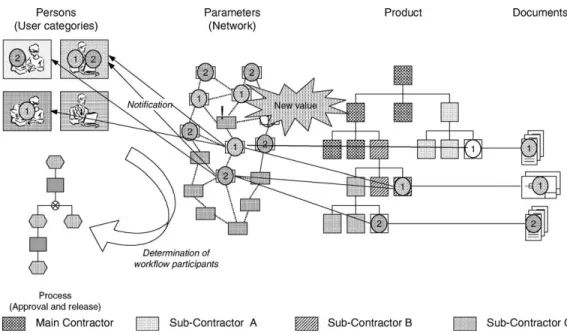
Once the parameter status is set to ‘‘in change’’, all users assigned to the user categories of this parameter are notified about the change. Each para-meter of the network is linked to elements of the product structure as well as to persons. Via the user roles, it becomes clear which persons must be informed whenever the status or the value of a particular parameter changes. Thus, the required participants of the approval and release workflow can also be identified (Fig. 9).
Step 3: Assessing the change impact. Once the change is approved on a parameter, this change might affect other adjacent parameters. The para-meter network controls the change propagation.
Fig. 9 gives an overview of the existing relations. The degree of interdependence can help to identify which parameters are subject to change. The system only makes participants aware of the existing rela-tion and the possible change propagarela-tion between the changed and the neighbouring parameters in the network. The co-ordinator and the collaborators must jointly clarify whether these parameters are actually affected by the change. As long as this clarification is not completed, the neighbouring parameters remain in their current status. Neigh-bouring parameters are examined in order of rela-tionship degree (e.g. start with 1st order).
The parameter network helps to identify neigh-bouring parameters, which are possibly affected by the initial change. However, the involved people themselves must perform identification of the actual impact. As long as the adjacent parameters are not declared affected, they remain in their current sta-tus. As a result of the discussion on the extended change, some parameters are finally declared not affected by the change and therefore removed from the list. Others are identified as affected by the
Step 4: Joint approval and release. The changed parameters and their values are approved and released by means of a parameter-based workflow (seeFig. 10). However, unlike iterative design all parameters on the list become the input to a single workflow.
Step 5: Recording the change for historical refer-ence. Information related to parameter change (such as discussion logs) is stored and recorded to be reused when dealing with similar problems. It is instructive to note how this relates to document driven ECM. The steps in a document driven process may be:
(1) Someone identifies the need for a change. If a formal process exists, then:
(2) The ECR is submitted.
(3) The process for approval is started. (4) The approval is granted.
(5) The ECO is released.
(6) The change is implemented and documented. Note that this process deals with documenting a request, its approval, and implementation. It does not deal with the engineering work involved. No colla-borative processes are specified nor is there any formal procedure to deal with change propagation.
6. Implementation and test
The following sections describe requirements for implementation in a computer-based system, and initial test results. This approach was implemented within the PDM system of one of the partners, and tested in a design effort involving three other partners.
6.1. Requirements for implementation
Implementing this approach requires capabilities in several computer systems. The engineering data sys-tem (here taken to be a PDM syssys-tem) must meet the specifications discussed in the previous sections. The new system specifically must:
1. Manage the product data (product structure, drawing, parameters, components, etc.) in a distributed collaborative environment.
2. Link different computers available in different departments and companies in order to facilitate processing engineering changes. This also im-poses the requirement that these computers share adequate communication capabilities.
3. Support the collaborative ECM activities and information availability. As data are not necessarily centralised, a system must offer access to data hosted at different companies.
4. Provide access security to authorised persons. As these people can be internal or external, a secure Extranet may be the best approach.
5. Provide functionality to link product structure to parameters, roles, and users. This is the most important missing functionality in current PDM technology.
A workflow system must:
6. Be able to handle the identified user categories and the role access.
7. Support parameter evolution.
A communication system (e.g. PDM messaging and/or external mail) must:
8. Provide a notification service to report requesting, authorising, approving, releasing and completing ECM activities.
The approach described in the previous sections was implemented in a new generation of PDM system, provided by one of the consortium partners. This secure web-based PDM system supports the metho-dology described in this paper and supports the above requirements.
6.2. Applicability and scalability of the parameter approach
The number of parameters needed to fully determine the properties of a product depends on its complexity. An automobile can be described from 105to 106, while an aircraft or a ship may have more than 106parameters. Aerospace engineers often joke that a modern com-mercial aircraft is ‘‘one million individual parts flying in close formation’’. Consequently, to capture and manage all describing parameters in one system becomes unrea-listic for products of medium complexity. Therefore, a selection has to be made depending on the purpose of the parameter deployment.
For the management of engineering change pro-cesses in a multi-company simultaneous engineering environment, the most important parameters are those that affect activities in more than one of the involved companies. These include:
System parameters, which affect either all or most of the items in the product structure (e.g. allowable total weight, system power, available building space).
Interface parameters which specify a relation between two product structure items engineered by different companies in terms of form, function or material (e.g. fitting dimensions, forces to be trans-mitted, ease of welding of the selected materials). If the number of considered parameters is limited to the above described system and interface parameters,
in an actual design exercise. Initial test results will be discussed in the next sub-section.
The approach was further presented to several auto-motive suppliers and one of the leading European aerospace companies. All of them confirmed its applic-ability and relevance for their sector. The authors have also discussed this approach with one of the more prolific researchers in this area, G.Q. Huang (author of, e.g.[3,4,11]). Professor Huang3found the parameter approach to be rigorous and sound but did caution that it may impose excessive workloads in practice. The next section will discuss results from the test case.
6.3. Initial implementation results
The SIMNET project included a test of the para-meter-based approach. The main contractor, Siemens SGP, and the brake supplier, Knorr Bremse co-oper-ated in the design of a new railcar bogy. Schmitt and Fortmu¨ller [33]4 describe the results of this test in detail. However, as that document contains company sensitive material, it is confidential. We can present some of the findings reported in that document. Those interested in greater detail are encouraged to contact Schmitt or Fortmu¨ller directly.
After testing, the end-users were asked to evaluate several aspects of parameter-based concurrent engi-neering on the basis of potential value and value already achieved in the implementation. The use of the para-meter network to trace change propagation was among the concepts evaluated. The users found the parameter-based concurrent engineering concepts of immediate potential value and the implementation ranked almost as high. The slightly lower score for implementation may be interpreted as the users finding value in the imple-mentation but that there were still details to be improved.
more concerns. Once again, the method scored higher than the implementation.
Specific concerns in implementation of the change management included the difficulty of distinguishing between first and higher-order relations, that the change procedure might be overly simplified, and that problems may emerge when parameters appear on more than one change list.
We are encouraged by these initial test results. The end-users saw the value in the approach and method and were able to suggest areas were the implementa-tion could be improved.
7. Conclusions and perspectives
This paper found a scarcity of research supporting engineering change management where the product design effort is concurrent and involves several com-panies. Furthermore, supporting computer tools are used infrequently, and most often limited to the man-agement of formal document-based approval and release procedures. There is also a lack of IT support addressing change propagation in the case of engi-neering change.
We then presented a parameter-based approach to ECM that aims to support multi-company concurrent engineering efforts. This approach can provide quick and early insight to suppliers about the impact of proposed changes. The parameter capture and man-agement focuses on system and interface parameters, which are relevant to more than one company within the design effort. This approach can have several advantages. It supports communication in a distributed engineering environment. It helps to facilitate infor-mation exchange, retrieval, sharing, and use. Via the assignment of users to roles, persons can be assigned to each parameter regardless of their company affilia-tion. These persons are automatically informed as to the change of a parameter value or status and are
3G.Q. Huang, June 2001, private communication.
4Please contact the first author for details (email:
incorporated as workflow participants into a para-meter-based approval and release process. The gen-eration of parameter relations in connection with the assignment of parameters to a product’s structure helps tracing of change propagation.
This approach can benefit both researchers and practitioners. It offers a framework and a system for companies wishing to implement ECM efforts that span company borders. In addition, software engineering companies can use this framework to develop a new generation of ECM tools that support tracking change propagation, such as the messaging function within collaborative product data management (CPDM).
While of broader relevance, this paper focuses on a specific design environment, leaves some questions un-addressed, and places requirements on firms wishing to implement it. First, it has been applied primarily to an engineer-to-order setting. This environment often must deal with a large number of engineering changes. Sec-ond, this approach requires training in using the (for example PDM) system. Cost (in terms of saved engi-neering time and the impact of improved quality of engineering data) was not addressed in the paper. How-ever, the test case showed that engineers saw the benefit of the approach and were able to suggest areas for improvement in the implementation. The concept was well received by these users. However, as end-users gave higher evaluations to the concept than the implementa-tion, there is room for refinement. Their concern about the impact of simultaneous changes reflects Huang’s concern about workload and suggests further testing.
Acknowledgements
The project to which the above results refer was co-funded by the European Commission under the ESPRIT programme (project No. 26780—SIMNET: Workflow Management for Simultaneous Engineering Networks—http://www.imw.tu-claushal.de/simnet). The project partners were:
Siemens SGP Verkehrstechnik GmbH, Graz, Aus-tria (Co-ordinator);
EignerþPartner AG, Karlsruhe, Germany;
Knorr-Bremse Systeme fu¨r Schienenfahrzeuge GmbH, Mu¨nchen, Germany;
Mission Critical SA, Waterloo, Belgium;
BETA at Eindhoven University of Technology, Eindhoven, The Netherlands;
TU Clausthal, Clausthal-Zellerfeld, Germany;
IPS Ingenierı´a de Productos, Procesos y Sistemas Integrados S.L., Valencia, Spain.
The authors wish to acknowledge the Commission for its support. They furthermore wish to acknowledge the SIMNET project partners for their contribution during the development of various ideas and concepts presented in this paper.
References
[1] B. Prasad, Concurrent Engineering Fundamentals: Integrated Product and Process Organisation, vol. I, Prentice-Hall, Upper Saddle River, NJ, 1996.
[2] C. Terwiesch, C.H. Loch, Managing the process of engineer-ing change orders: the case of the climate control system in automobile development, Journal of Product Innovation Management 16 (1999) 160–172.
[3] G.Q. Huang, K.L. Mak, Current practices of engineering change management in UK manufacturing industries, Inter-national Journal of Operations and Production Management 19 (1) (1999) 21–37.
[4] G.Q. Huang, W.Y. Yee, K.L. Mak, Development of a web-based system for engineering change management, Robotics and Computer Integrated Manufacturing 17 (June) (2001) 255–267.
[5] R.P. Smith, S.D. Eppinger, Identifying controlling features of engineering design iteration, Management Science 43 (1997) 276–293.
[6] D. Ullman, The Mechanical Design Process, McGraw-Hill, New York, NY, 1997.
[7] J.C. Wortmann, D.R. Muntslag, P.J.M. Timmermans, Custo-mer-Driven Manufacturing, Chapman & Hall, London, 1997. [8] S. Goldman, R.N. Nagel, K. Preiss, Agile Competitors and Virtual Organisations, Norstrand Reinhold, New York, 1995. [9] M. Ader, Technologies for the Virtual Enterprise, http://
www.e-workflow.org/downloads/gue-tec.pdf, 2001. [10] W. Eversheim, A. Roggatz, H.-J. Zimmermann, T. Derichs,
Information management for concurrent engineering, Eur-opean Journal of Operational Research 100 (July) (1997) 253–265.
[11] G.K. Huang, K.L. Mak, Computer aids for engineering change control, Journal of Materials Processing Technology 76 (1998) 19–187.
[12] K.B. Clark, T. Fujimoto, Product Development Performance: Strategy, Organisation and Management in the World Auto Industry, Harvard Business School Press, Cambridge, MA, 1991.
[13] CIMdatahttp://www.cimdata.com, 2002.
[14] I.C. Wright, A review of research into engineering change management: implication for product design, Design Studies 18 (January) (1997) 34–42.
of engineering change control, Computing and Control Engineering Journal (March) (1992) 63–70.
[18] R.G. Boznak, Competitive product development, Business One Irwin/Quality Press, Milwaukee, WI, 1993.
[19] M.W. Kidd, Thompson, Engineering Design Change Manage-ment, Integrated Manufacturing Systems, vol. 11 (1), 2000, pp. 74–77.
[20] F. Watts, Engineering changes: a case study, Production and Inventory Management Journal 25 (Part 4) (1984) 55–62. [21] L.G. Soderberg, Facing up to the engineering gap, McKinsey
Quarterly Spring 3 (1989) 3–23.
[22] M.A. Reidelbach, Engineering change management in long-lead-time environments, Production and Inventory Manage-ment Journal 32 (2) (1991) 84–88.
[23] K. Krishnamurthy, K.H. Law, Change management for collaborative engineering, Computing in Civil Engineering 2 (1995) 1110–1117.
[24] S.B. Harris, Business strategy and the role of the engineering product data management: a literature review and summary of the emerging research questions, Part B, Journal of Engineering Manufacture, Proceedings of IMechE 210 (1996) 217–219. [25] G. Harhalakis, Engineering changes for made-to-order
pro-ducts: how an mrp ii system should handle them, Engineering Management International 4 (1986) 19–36.
[26] K.J. Balcerak, B.G. Dale, Engineering change administration: the key issues, Computer-Integrated Manufacturing Systems 5 (2) (1992) 125–132.
[27] R.K. Moenart, W.E. Souder, A. Meyer, D. Deschoolmester, R&D—Marketing integration mechanisms, communication flows, and innovation success, Journal of Product Innovation Management 11 (1994) 31–45.
[28] W.E. Souder, R.K. Moenart, An information uncertainty model for integrating marketing and R&D personnel, Journal of Management Studies 29 (1992) 485–512.
[29] K. Nichols, Getting engineering changes under control, Journal of Engineering Design 1 (1) (1990) 1–6.
[30] R. Schmitt, Engineering workflow in the supply chain, in: Proceedings of the 1st European Engineering User Con-ference (e.e.u.c.), Munich, 30 November to 1 December 2000, pp. 77–78.
[31] R. Schmitt, (in German) Unternehmensu¨bergreifender En-gineering Workflow—Verteilte Produktentwicklung auf der Grundlage eines parameterbasierten Daten—und Prozess-managements, Clausthal-Zellerfeld, ISBN 3-89720-495-9, 2001.
changes through focused manufacturing knowledge, IEEE Transactions on Engineering Management 40 (1) (1993) 54–58. [36] S.W. McKnight, J.M. Jackson, Simultaneous engineering saves manufacturing lead time, cost and frustration, Industrial Engineering 21 (8) (1989) 25–27.
[37] MIL-STD-973, Configuration Management, http://qa.pica.ar-my.mil/stdz/MIL-STD-973/default.htm (see also http://www. mil-std-973.com), 2001.
Kamel Rouibah graduated from Ecole Nationale Polytechnique d’Alger (Algeria) in 1992. He received the Mas-ter’s degree from the Institut National Polytechnique de Grenoble (France) in 1994 and a PhD degree from Ecole Supe´rieure des Affaires de Grenoble (France) in 1998. From 1999 to 2001, he worked as a research associate in the Faculty of Technology Management, Information Technology Department, at the Eindhoven University of Technology (The Netherlands). He was involved in two European Esprit Programme projects in the area of collaborative engineering. He is currently Assistant Professor of information systems at the College of Business Administration, Kuwait University. His research interests include design of strategic information systems, workflow management, product data manage-ment and business process reengineering.
Kevin Caskeyearned his doctorate in Industrial Engineering at the University of Washington (Seattle) while a full-time employee of Boeing Computer Services, where he was a simulation specialist. He is currently Assistant Professor of Opera-tions Management in the School of Busi-ness at SUNY, New Paltz, New York. Between his time at Boeing and joining the SUNY faculty, Dr. Caskey enjoyed several years as a research scientist in Germany and The Netherlands. There, his research focused on logistics, virtual enterprises, and electronic commerce. His research interests include optimisation and generalisation of simulation and its integration in decision support systems. Major application areas for such techniques include supply chain management and colla-borative engineering.