Dok. 44969-09 Sag 09/1437
Offshore Substation
HVAC System
ETS-09 Rev. 2
te
c
h
n
ic
a
l
st
a
n
d
a
rd
s
Revision survey
Document title HVAC System
Document no. 44972-09
Target group Fabrications Contractors and Designer for Offshore substations.
Revision Document status Writer Reviewer Approver
Init Date Init Date Init Date
1 xomo 12.10.09 N/A 12.10.09 HRI 12.10.09
2 Approved xomo 06.05.13 POD, PJV 06.05.13 POD 06.05.13
Minor alterations, type errors, rephrases’ e.t.c. where the meaning of the text is left unchanged are not shown.
Appendix no. and description
Revision
Document no. 44969-09, case 10/4054 ETS-09 v. 2
Table of contents
1. Scope 1
2. References 1
2.1 Codes and Standards 1
3. Definitions and Abbreviations 2
3.1 Definitions 2
3.2 Abbreviations 3
4. Technical Requirements 3
4.1 General 3
4.2 HVAC Design Basis 4
4.3 Indoor Climate 4 4.3.1 Pressurization 4 4.3.2 Air Quality 4 4.3.3 Human Comfort 5 4.3.4 Heating 5 4.3.5 Cooling 5 4.3.6 General 6
4.3.7 Noise and Vibration 6
4.4 Out Door Climate 6
4.5 Fresh Air Ventilation 6
4.5.1 Fresh air ventilation unit 7
4.6 Leakage 7
4.7 Ductwork and Components 7
4.7.1 Air Intakes and Exhausts 7
4.7.2 Fans and Motors 8
4.7.3 Moisture Separators and Filters 8
4.7.4 Heating / Cooling Coils 9
4.7.5 Ductwork 9 4.7.6 Dampers 10 4.7.7 Silencers 10 4.7.8 Control System 10 4.7.9 Insulation 11 4.8 Installation 11 4.8.1 General 11
4.8.2 Leakage Test, Air flow measurements and Pressure Test 11
4.9 Commissioning 11
5. Certificates / Data books 12
1.
Scope
This Technical Standard covers the design and materials for HVAC systems for. Semi-manned offshore substations, in accordance with the definition stipulated in DNV-OS-J201.
This ETS specifies requirements and gives recommendations for the indoor climate of offshore substations and for the design and engineering of HVAC systems. It takes into account the requirements for both people and electronic equipment.
Compliance is required with all applicable parts of the Codes and Standards specified. The Technical Standard is one of a whole set of Technical Standards. It contains additional Energinet.dk requirements or specifies requirements where the Regulations, Codes and Standards allow alternatives.
2.
References
2.1 Codes and Standards
DS/EN ISO 15138 Petroleum and Natural gas Industries – Offshore production installations – Heating, ventilation and air-conditioning.
DS 447 Code of Practice for mechanical ventilation installations DS 452 Code of practice for thermal insulation of technical
service and supply systems in buildings DS 474 Code for Indoor Thermal Climate
Eurovent 2/2 Air leakage rate in sheet metal air distribution systems SBI – 102 Danish Building Research Institute (SBI) – Specification
102. Measurements in ventilating systems. 2006/42/EC
DNV-OS-J201
Machinery Directive (DK version = 2006/42/EF) Offshore Substations for Wind Farms
Document no. 44969-09, case 10/4054 ETS-09 v. 2 2
3.
Definitions and Abbreviations
3.1 Definitions
Moisture separator – filter coalesce
A single component including weather protection louver / moisture eliminator, a bag or panel coalesce a filter section and if necessary another moisture eliminator or split into separate parts comprising of the above mentioned parts.
Air Handling unit (Self-contained)
Chilled water unit (Compressor type).
Direct expansion (DX) chiller.
Fresh air ventilation unit Fan coil unit
An air handling unit, located in the space which it serves, which re-circulates the air in that space to the required conditions. A self-contained air handling unit does not normally involve a ducting system. A unit similar to a direct expansion (DX) chiller but including a heat exchanger which utilises the vaporising refrigerant's latent heat to cool a chilled water circuit to the required temperature.
A unit consisting of a compressor and a condenser. The refrigerant vapour is compressed to a certain pressure, condensed to liquid refrigerant and then vaporised, thus utilising the vaporising refrigerant's latent heat in a cooling coil (separate from the chiller). The vaporised refrigerant is returned from the coil to the compressor.
An air handling unit in which the fresh air is handled to the required conditions and used as ventilation air. HVAC equipment through which air is re-circulated from the space in which it is located. The purpose of this re-circulation is to cool or heat this air to the conditions required for the space. This unit is normally connected to the chilled water or the DX system.
Shall: Verbal form used to indicate requirements to be strictly followed in order to conform to the standard and from which no deviation is permitted, unless accepted by all parties.
Should: Verbal form used to indicate that among several possibilities one is recommended as particularly suitable, without mentioning or excluding others, or that a certain course of action is preferred but not necessarily required.
May: Verbal form used to indicate a course of action permissible within the limits of the standard.
Can: Verbal form used for statements of possibility and capability, whether material, physical or casual.
3.2 Abbreviations
HVAC Heating, Ventilation and Air Conditioning DS Danish Standard – Code of Practice EN European Standard – Code of Practice IEC International Electrotechnical Commission ISO International Organisation for Standardization NGTE National Gas Turbine Establishment
4.
Technical Requirements
4.1 General
Offshore substations may require climatic conditioning (i.e. heating, ventilation and/or air conditioning) in order to maintain the temperature, relative humidity and air quality within defined limits. In this way reliable operation of electronic
equipment and human working conditions are enhanced.
HVAC systems are generally supplied by specialised Manufacturers as package units or as single components. Standard industrial HVAC equipment should be used.
Document no. 44969-09, case 10/4054 ETS-09 v. 2 4 It shall be ensured that sufficient space in plant buildings is reserved for HVAC
equipment and its ducting.
4.2 HVAC Design Basis
A design basis as stipulated in DS/EN ISO 15138 shall be prepared by the Contractor.
The primary goals of the ventilation system shall be identified, some of the goals are:
Prevent ingress of salt particles and salt- water aerosols, if present, into relevant areas through pressurization and installation of efficient moisture eliminators and filter coalesces.
Remove generated heat / supply heated air in winter time, and keep a controlled indoor climate in which personnel, plant and systems can operate effectively including smoke control.
Ventilation shall be maintained to equipment and rooms that need to be operational during an emergency situation when the main source of power is unavailable, if required.
4.3 Indoor Climate
Recommended indoor climate/environmental conditions as given in DS/EN ISO 15138, shall be fulfilled as a minimum. Recommendations given in DS447 can be followed.
4.3.1 Pressurization
Indoor premises/rooms, where required, shall be kept under a relative overpressure to reduce the concentration of salt-water aerosols, dust and water particles and keep the indoor air clean.
Pressurization shall be minimum 50 Pa for technical rooms, if required by design, and for the accommodation area within the range of 25 Pa to 65 Pa with respect to outside atmosphere at design wind speed.
4.3.2 Air Quality
Ventilation rates (in terms of changes per hour) shall be determined taking into account the rate of leakage through doors and wall penetrations, the thermal requirements of the rooms and the required airflow to remove polluted air. Rooms should be equipped with pressure control dampers to adjust the pressure in each room to the required level.
Workshops on the platform shall be provided for process ventilation if required by the design. Process ventilation can comprise of welding exhaust arms, fans and filters. Exhaust air shall be led to safe areas and well clear of access ways.
4.3.3 Human Comfort
Recommended indoor temperature conditions as given in DS/EN ISO 15138 shall be fulfilled as a minimum.
Humidity control shall be provided by either the individual self-contained air handling units or by the central fresh air ventilation unit.
4.3.4 Heating
Heating may be required to raise the temperature inside a room to the required level. In the heating capacity calculations the dissipated heat from personnel, lighting and electronic equipment shall not be included. Heat losses through walls, floors and roofs shall be taken into account.
Electrical or hot water may be considered as a heating medium for a central heating system. The fresh air ventilation unit and the re-circulation air handling units can, if applicable, be heated through this central heating system.
Vital rooms (e.g. control room, instrument auxiliary room, electrical auxiliary room etc.) may be heated through re-circulation air handling units.
For other rooms heating can be provided by either individual fan coil units, individual electric after-heaters or a central heating system.
4.3.5 Cooling
Cooling may be required to lower the temperature inside a room to the required level. Cooling capacity calculations should be based on heat gain from sources such as personnel, electronic equipment, lighting, fresh air intake, walls, roofs, windows etc.
The heat generated in the rooms shall be removed by supplying cooled air. For cooling of rooms containing vital electronic equipment, self-contained air handling units can be used.
Direct expansion (DX) Chillers or chilled water can be applied as a cooling medium. Such units shall be located inside the rooms they serve. Drainage from the unites shall be routed to the drain system.
In order to allow for maintenance and failure of such units, redundancy shall be provided. The capacity of the individual self-contained units shall be such that the normal climatic requirements are met even if one unit fails.
Document no. 44969-09, case 10/4054 ETS-09 v. 2 6
4.3.6 General
Duct or unit-mounted heating and cooling coils units shall be automatically temperature-controlled by a duct- or room-mounted sensor modulating a heating/cooling-medium proportional controller.
Where both heating and cooling coils are employed, controls shall be interlocked to ensure complementary operation.
4.3.7 Noise and Vibration
Recommended maximum indoor noise levels as given in DS/EN ISO 15138, shall be fulfilled as a minimum.
Noise caused by HVAC installations can be reduced by applying one or more of the following:
- air duct silencers;
- soundproofing of air ducts; - quiet self-contained equipment;
To reduce vibration from rotating and vibrating items of equipment they shall be isolated from piping, ducting and structures by means of flexible piping, air duct connectors, vibration isolators, etc.
4.4 Out Door Climate
The recommendations stipulated in DS/EN ISO 15138 for external meteorological conditions shall be applied by the design.
4.5 Fresh Air Ventilation
Fresh air ventilation may be required in order to:
provide a minimum fresh air intake quantity per unit of time;
maintain an over-pressure in order to prevent the ingress of contaminants;
compensate for specific exhausts such as those in, a battery room or workshops.
Requirements for fresh air ventilation systems are:
A positive flow from outdoors to indoors and back shall be accomplished.
The air flow direction shall be such that the flow is from clean rooms, e.g. control room, instrument auxiliary room, telecommunication room and
computer room, to rooms with air polluting (fouling) equipment e.g. battery room, HVAC machine room and workshops.
4.5.1 Fresh air ventilation unit
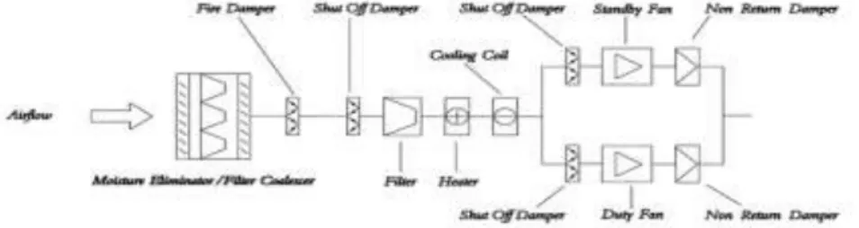
Components in fresh air ventilation units shall fulfil demands as stated in previous sections. Air handling units shall fulfil demands as listed in DS/EN ISO 15138.
Fig 1. Fresh air ventilation unit.
4.6 Leakage
Guidelines for the maximum leakage factor given in DS/EN ISO 15138, Eurovent 2/2 and DS447 shall be followed.
4.7 Ductwork and Components
4.7.1 Air Intakes and Exhausts
HVAC air intakes shall be equipped with efficient weather protection louvers / moisture eliminators. The louvers shall be able to remove the majority of the liquid (rain, sea spray, coarse aerosols), the moisture separation efficiency shall typically be 96 % for droplet sizes of 30 μm and larger at a system velocity of 1 m/s. HVAC air exhausts shall be equipped with efficient weather protection louvers. A screen or mesh sized to provide protection against birds shall be fitted to the air inlet and exhaust ducts.
Air intakes and exhausts shall be placed far apart from each other. Inflow from generator exhaust, exhaust from combustion engines, fired units or ventilation exhaust shall be avoided.
Document no. 44969-09, case 10/4054 ETS-09 v. 2 8 The air intake shall be located in safe area.
4.7.2 Fans and Motors
Fans and motors shall be selected for optimum efficiency with regard to power consumption, sound level and fan efficiency.
If reliability of the HVAC system is deemed important, i.e. if cooled air is provided by the HVAC system to remove heat generated from equipment, the air handling units shall be provided with two fans, one duty and one stand-by to ensure ventilation if a fan fails. Shut off dampers shall be placed upstream the fans and non-return
dampers downstream the fans, in case of repair of a fan, the fan shall be able to be dismantled without air backflow from the fan running, see. Fig.1.
Automatic switch over between duty and standby fan shall be provided. Signal of air flow failure in the ducts, via flow switches in the ducts, or automatic switch over from duty to stand-by fan shall be provided.
4.7.3 Moisture Separators and Filters
Efficient moisture separators and filters shall be installed in the HVAC system air intake.
The moisture removal and filtration function can be incorporated into a single component including weather protection louver/moisture eliminator, a bag or panel coalesce, a filter section and possibly another moisture eliminator or split into separate parts comprising of the above mentioned parts.
An efficient moisture separator can be split into 3 stages as described below:
Stage 1 is the ‘bulk water’ removal stage. In this stage the majority of the liquid (rain, sea spray, coarse aerosols) entering the intake is removed and drained away. Stage 1 is typically a vane separator/weather protection louver.
Stage 2 is the coalescence stage, where fine aerosols that have penetrated the first stage are coalesced to form larger droplets that can be easily removed by the third stage. Stage 2 is often a filtration stage designed to remove dust and other solid particulate.
Stage 3 is typically a vane separator or similar, which stops any concentrated saline solution that has passed through Stages 1 and 2. The entrained liquid is captured and removed from the intake by a manometrically sealed drainage system.
Arrangements can vary dependant on the manufacturer, guidelines to typical air filtration requirements for various rooms can be found in DS/EN ISO 15138.
The louver / filter/ coalesce separator should be able to reduce the salt-in-air content at the output to 0.01 x 10⁻⁶ by mass against the NGTE (National Gas Turbine Establishment) Standard 30 knot aerosol.
The pressure drop across moisture separators and filters shall be kept at a minimum.
4.7.4 Heating / Cooling Coils
Electrical heaters
Electrical heaters shall fulfil guidelines given in DS/EN ISO 15138.
All heaters shall be installed with “high air temperature” or “high element-surface temperature” thermal cut-outs.
Cooling Coils
Cooling coils can be of direct expansion refrigerant or fluid type. Cooling coils shall be selected to avoid moisture carry-over into the air stream. Cooling coils shall be provided with frost protection and surface temperature shall be measured, i.e. the cooling coil shall be placed downstream the heater, to prevent freezing of the coil in winter conditions.
Water pipes crossing rooms with electrical equipment should be avoided where possible. If not possible electrical equipment shall be screened against splash and spray in case of a rupture.
4.7.5 Ductwork
Ducts, equipment and supports placed outside enclosures shall be designed to withstand offshore conditions, wind loads shall be taken into account and ducts shall be made of corrosion resistant material, stainless steel. Ducts and supports placed inside enclosures shall be made of materials with a lifetime equal to the design lifetime of the platform. Guidelines for ductwork and materials as listed in DS/EN 15138 shall be followed.
Recommended maximum velocities in duct systems as given in DS/EN ISO 15138 shall be fulfilled. Duct systems shall be designed to fulfil the acoustic requirements and requirements for the maximum air leakage percentage as given in DS447. Duct systems should be self balancing as far as possible; where this is not the case flow balancing dampers shall be installed.
Document no. 44969-09, case 10/4054 ETS-09 v. 2 10
4.7.6 Dampers
Dampers shall fulfil guidelines given in DS/EN ISO 15138. Fire dampers
Fire dampers shall be able to maintain fire-rated barriers when penetrated by HVAC ducts.
Proximity or limit switches to indicate status closed and/or open positions shall be installed on the fire dampers.
The dampers shall be kept in open position by a pneumatic single-action spring-return actuator or a spring-spring-return electric motor depending on if it is supplied with air or electric power. In case of loss of air or electric power the dampers shall close. A thermal device shall be installed to activate the damper actuator and close the damper in the event of an unacceptable temperature rise in the duct.
Pressure-relief dampers
Pressure-relief dampers shall be controlled automatically by tension spring or counterbalance weight, set to restrict blade opening until a preset pressure is exceeded.
4.7.7 Silencers
Silencers and sound attenuators shall be selected to reduce duct carried noise from ventilation fans, dampers or other noise sources in the ventilation system.
Recommended HVAC noise limits given in DS/EN ISO 15138 shall be fulfilled as a minimum.
4.7.8 Control System
A local control system (such as a programmable RIO) for the HVAC system shall be installed. The local control system shall be linked up to the platforms main control system via a communication bus from where the HVAC system is monitored and all control functions can be accessed.
All important information on temperature, air flow failure, equipment failure and status on the system shall be collected. The HVAC system shall be accessible via an IP-connection. Status indicators and operations shall be available via this web interface. The connection shall be accessible via a standard browser (e.g Internet Explore).
The following controls, indicators and alarms should be present: Controls
The following controls should, as minimum, be provided: Start/stop fans, Automatic changeover switch with selector for each duty/standby fan, Open/Close of dampers, and change of temperature set-points.
Indicators
The following indicators should as minimum be provided: Run/Stop/Tripped fans, Filter dirty, On/tripped heater, lamp test, On/tripped each package equipment item, Open – each fire/gas damper, Close – each fire/gas damper, Loss of pressurization – any area requiring pressurization, temperature readouts.
Alarms
Alarm should as minimum be given for: Fan trip, heater trip, filter dirty, package equipment trip, loss of pressurization, fire damper operating-mode failure, high/low temperatures.
4.7.9 Insulation
Ducts placed indoor shall be insulated against condensation, heat loss and fire, see Insulation guidance – DS/EN ISO 15138. Insulating materials shall be fire resistant.
4.8 Installation
4.8.1 General
Installation guidance as specified in DS/EN ISO 15138 should be followed.
4.8.2 Leakage Test, Air flow measurements and Pressure Test
Leakage test, air flow measurements and pressure test should be carried out in accordance with relevant codes such as Eurovent 2/2, SBI specification 102 and relevant DS/EN codes of practice
A report with all measured values, method, and place marked up on drawings and instrument type shall be performed and issued.
4.9 Commissioning
The HVAC system shall be commissioned in accordance with the project requirements, at the latest before load-out. Unless otherwise specified by the Employer, the Supplier of the HVAC system shall provide all test equipment required to commission and maintain the whole HVAC system. Commissioning procedures should shall as a minimum, but not limited to include:
Measurements of design airflows and air temperatures
Differential pressures
Document no. 44969-09, case 10/4054 ETS-09 v. 2 12 All measurements and settings should be conducted using calibrated instruments,
and the results shall be documented in a measurement report.
Acceptance of the HVAC plant should not take place until satisfactory measurements and commissioning has been completed.
5.
Certificates / Data books
5.1 General
Certificates and data for all equipment and parts of the HVAC system shall be collected in Data books. Service procedures and service intervals shall be assembled in a service book.