e-ISSN: 2278-067X, p-ISSN: 2278-800X, www.ijerd.com
Volume 10, Issue 10 (October 2014), PP.14-23
Analysis and Control for Selective Compensation of Power
Quality Problems through Three Phase Four Wire UPQC
Dr.B.Suresh Kumar
CBIT-EEEDAbstract:- This paper presents a novel control strategy for selective compensation of power quality (PQ) problems, depending upon the limited rating of voltage source inverters (VSIs), through a unified power quality conditioner (UPQC) in a three-phase four-wire distribution system. The UPQC is realized by the integration of series and shunt active power filters (APFs) sharing a common dc bus capacitor. The shunt APF is realized using a three-phase, four-leg voltage source inverter (VSI), while a three-leg VSI is employed for the series APF of the three-phase four-wire UPQC. The control scheme for the shunt APF, decomposes the load current into harmonic components generated by consumer and distorted utility. In addition to this, the positive and negative sequence fundamental frequency active components, the reactive components and harmonic components of load currents are decomposed in synchronous reference frame (SRF). The control scheme of the shunt APF performs with priority based schemes, which respects the limited rating of the VSI. For voltage harmonic mitigation, a control scheme based on SRF theory is employed for the series APF of the UPQC. The performance of the control scheme of the UPQC is validated through simulations using MATLAB software with its Simulink and Power System Block set toolboxes.
Keywords:- Current decomposition, Neutral current compensation, Selective compensation, Unified power quality conditioner (UPQC).
I.
INTRODUCTION
The serious drawback of PWM inverters is that Nowadays, Custom Power Devices (CPDs) [1], [2], which are applicable to distribution systems for enhancing reliability and quality of power, are gaining popularity. Custom power devices include static shunt compensator or distribution static compensator (D-STATCOM) [3] to compensate current based distortions and series static compensators or a dynamic voltage restorers (DVR) for the mitigation of voltage based distortions [4]. However, their capabilities are usually limited as they can only solve one or two power quality (PQ) problems. Recent re- search efforts have been made toward utilizing a device called UPQC to solve almost all PQ problems [5]. Generally CPDs are designed for full compensation irrespective of the priorities of consumers. Very few papers are reported in literature for the selective compensation of power quality problems using D- STATCOM [3], DVR [4] and UPQC/UCPC [5], [6]. The selec- tive harmonic elimination method (SHEM) [3], selective volt- age harmonic compensation scheme [4], harmonic selective UPQC based on multi variable regulator (MVR) [5] and UCPC with an array of resonant harmonic controllers [6] are some of the techniques used for selective compensation in CPDs. On the other hand, different topologies of APFs are reported in the literature for selective compensation. These topologies estimate the derived components based on p-q theory [7], modified p-q theory [8], FBD theory [9], orthogonal decom- position [10], Lagrange multiplier-based decomposition [11], estimation based on neural networks [12], etc. Unfortunately, these control schemes utilizes complex calculations and most of them are not employed for undistorted mains conditions. Further, some schemes based on notch filter [11] and adaptive techniques [13] are used to compute the decompositions of current. Apart from this, methods based on frequency domain approach have been reported, which separate out the customer and supply side harmonic contributions [17], [18]. Also, a scheme based on current decomposition technique in time domain is also employed for selective compensation by a shunt APF [14]. An approach based on frequency domain approach is accurate but involves lot of computation, hence not suitable for on-line applications while, time domain approach is fast but limited to single node applications.
In this paper, the advantages of time and frequency domain approaches has been combined to obtain flexible control of current based distortions using a three-phase four-wire UPQC. The customer and supply side harmonic contributions areseparate out based on the method by Srinivasan [16] and in addition to this; a simple SRF-based scheme is used to decompose the load current into four parts [14]. Those are positive sequence fundamental frequency active current (iLR1+), positive sequence fundamental frequency reactive current (iLX1+),
current components, the selective compensation of combinations of them can be made, which respects the limited rating of the shunt APF of three-phase four-wire UPQC and also attributes the responsibility of the customer and the utility at the point of common coupling. On the other hand, a simple control scheme based on SRF theory is used for the control of the series APF of the UPQC. In this control scheme for UPQC, the current/voltage control is applied over the fundamental supply currents/voltages instead of fast changing APFs currents/voltages, thereby reducing the computational delay. In addition to this, for the mitigation of source neutral current by the 4th leg of the shunt APF VSI, the load or the filter neutral current is not sensed, thereby reducing the numbers of current sensors. The effectiveness and dynamics of the scheme with selective compensation under varying load conditions is demonstrated through simulated waveforms using SPS Mat lab/Simulink environment.
Fig 1 Configuration of 3P-4W UPQC
II.
SYSTEM CONFIGURATION
Fig 2 Control Scheme of Series APF
A small capacity rated R-C filter is connected in parallel with the secondary of each series transformer to eliminate the high switching ripple content in the series active filter injected voltage. The VSIs for both the series and shunt APFs are implemented with IGBTs (Insulated Gate Bipolar Transistors). In Fig. 1 (isa, isb, isc),
(ila, ilb, ilc) and (ifa, ifb, ifc,) represent the source currents, the load currents and the shunt APF currents in phase a,
b and c, respectively. The source neutral current, load neutral current and shunt APF neutral current are represented by isn, iln and ifn, respectively. The injected voltages by the series APFs in phase a, b and c are
represented by vinja, vinjb and vinjc, respectively. The load under consideration is a combination of linear and
non-linear type. The values of the circuit parameters and the loads under consideration are given in the Appendix.
III.
CONTROL SCHEME OF SERIES APF
The control strategy is aimed mainly at computing the three-phase reference voltages at the load terminal voltages (vla∗, vlb∗ and vlc∗), which cancel out the distortions present in the supply voltages
(vsa, vsb and vsc) by injecting voltages (vinja, vinjb, and vinjc), thus making the voltage at PCC (vla, vlb, and vlc)
perfectly sinusoidal with a desired amplitude. In other words, the sum of the supply voltage and the injected series filter voltage makes the desired voltage at the load terminals.
The control strategy for the series APF is shown in Fig 2. Since the supply voltage is distorted, a phase locked loop (PLL) is used to achieve synchronization with the supply voltage [15]. Three-phase distorted supply voltages are sensed and given to PLL which generates two quadrature unit vectors (sinωt,cosωt). The sensed supply voltage is multiplied by a suitable value of the gain before being given as an input to the PLL. A discrete three-phase PLL having minimum frequency 50 Hz at a sampling time of 50 μ sec is used here. A distortion free, balanced, constant magnitude three-phase voltage has„d‟ components only, while the „q‟ and „0‟ components will be zero. Hence, with the help of the unit vectors (sinωt, cosωt) obtained from the PLL, an inverse Parks transformation is done for the desired peak value of the PCC voltage (ie.325V) using eqn. (1) as:
vla∗ vlb∗ vlc∗
=2 3
cosθ − sinθ 1 cos(𝜃 −2π
3) − sin( 𝜃 − 2π
3) 1
cos(𝜃 +2π
3) − sin( 𝜃 + 2π
3) 1
vd
0 0
(1)
All voltage regulation techniques are characterized by their susceptibility to system changes, harmonic injection, switching frequency, practical implementation and dynamic performance.
The hysteresis controller has been gaining much popularity among other techniques because of its robustness, simplicity of implementation and excellent dynamic performance [19]. Hence a hysteresis controller is used for the switching of series APF. The computed reference voltages from eqn. (1) are then given to the hysteresis controller along with the sensed three phase actual load voltages (vla, vlb, and vlc). The output of the
hysteresis controller is the switching signals to the six switches of the VSI of the series APF. The hysteresis controller generates the switching signals such that the voltage at the load terminals becomes perfectly sinusoidal with desired amplitude irrespective of harmonics present in supply voltages.
IV.
CONTROL SCHEME OF SHUNT APF
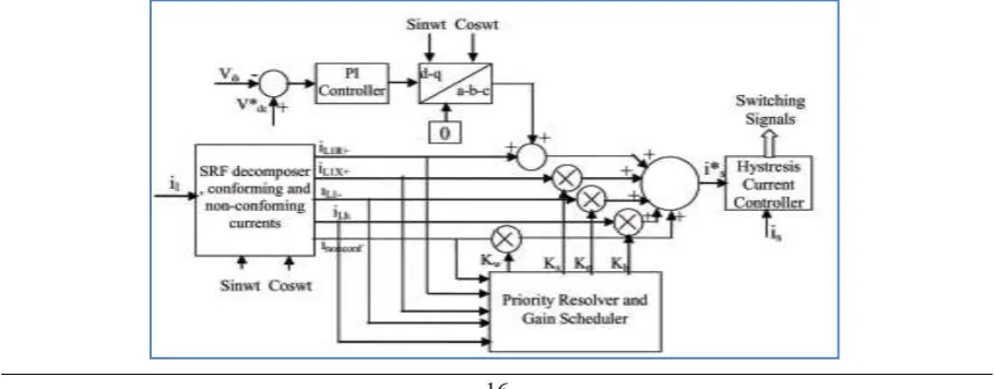
Fig 3 Control Scheme of Shunt APF
A. Separation of Customer and Supply Side Harmonic Contributions
Each frequency component of the total of the total source current in a distorted supply system can be divided in two components. One is the conforming current and the other is the non-conforming current. The sum of all of the frequency components of the source current having a similar shape as that of the supply voltage is called the total conforming current. This is the current that customers should be allowed to draw from distorted utility voltages without any penalty. On the other hand, sum of all of the frequency a component that are produced by the consumer load, for a sinusoidal supply voltage, is called total non-conforming current, which the shunt APF of the UPQC should compensate.
As per the Fourier series a non-sinusoidal signal can be expressed as a sum of the sinusoidal signals of various frequencies. Based on this, the distorted utility voltage and load current can be expressed as:vs t =
vn k
n=1 sin(nωt +θn) (2)
iL t = kn=1Insin(nωt + ∅n) (3)
Where vs t and iL t are the instantaneous source voltage and load current, vn and Inare the
maximum voltage of nth order utility voltage and load current, θn and ∅n are the phase angle of the nth order
utility voltage and the load current, and n is the order of harmonics. The total conforming current drawn from the utility is the portion of the current, which retains the same level of distortion as the voltage. The conforming current should have the same graphical pattern of variation as the utility voltage. It might have a time lag or lead depending on the load under consideration. Thus, the fundamental frequency component of the conforming current will be equal to the fundamental frequency component of the load current. All other frequency components will be in the same proportion as their counter parts in the utility voltage.
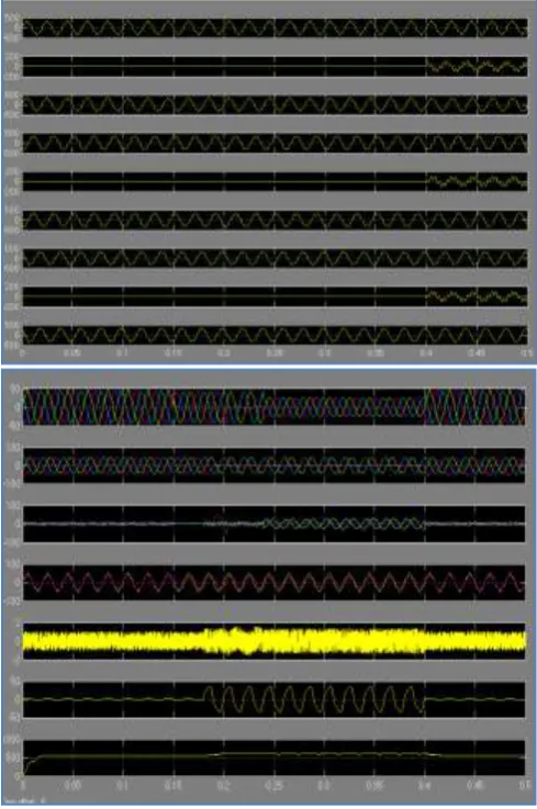
(a)
(b)
Fig.5Source voltage (vsb),source current(isb), load current(ilb),Compensator current(icb) and DC link
voltage (Vdc ),(b)source voltage and source currentin phase„a‟(vsa, isa), source voltage and source current in
phase „b‟(vsb, isb), and source voltage and source current in-phase „c‟(vsc, isc) and DC link voltage(Vdc)for
customer generated harmonics only, total source current harmonics compensation, total source currents harmonics and negative sequence component compensation and total source currents harmonics, negative sequence component compensation and reactive power compensation, respectively.
This can be mathematically expressed as follows:
iconf t = ( I1
V1)Vnsin(nωt +θn+ n(φ1−θ1))
k
n=1 (4)
Where, iconf t is the instantaneous value of the conforming current. The difference of conforming and load
current, which is equal to the total non-conforming current, will be provided by the shunt APF of UPQC and should be attributable to the customer.
B. Basic Theory of Current Decomposition
In this control scheme of shunt APF of a three-phase four wire UPQC, it is to use SRF theory to decompose the load currents instantaneously into active (iL1R) and reactive (iL1X ) components of positive and negative
sequence of currents (iL1−) at fundamental frequency and the harmonic frequencies (iLh). The SRF isolator
extracts the fundamental component of the load by the transformation ofiLa, iLb and iLc to the d-q reference
frame. In the synchronously rotating reference frame, the positive sequence components at the fundamental frequency (f1), are transformed into dc quantities and all harmonic and negative frequency components undergo
a frequency shift of f1 (50Hz). iLα
iLβ = 2
3
1 −1
2 −
1 2
0 3
2 −
3 2
iLa iLb iLc
(5)
iLd + iLq + =
cos(ω1t) sin(ω1t) −sin(ω1t) cos(ω1t)
iLα
The SRF isolator extracts the dc quantities by means of a low-pass filter (LPF) for each iLd and iLq,
realized by moving average at 100 Hz, since the waveform has a half wave symmetry in steady state. The averaged running at 100 Hz can compute and detect the deviation from the steady state condition within half a cycle. The extracted dc components iLdcD + and iLdcQ + are transformed back into the first a-b frame and then
into the a-b-c coordinates to obtain the net positive sequence fundamental component as follows:
iL1α+ iL1β+ =
cos(ω1t) −sin(ω1t) sin(ω1t) cos(ω1t)
iiLdcD + LdcQ + (7)
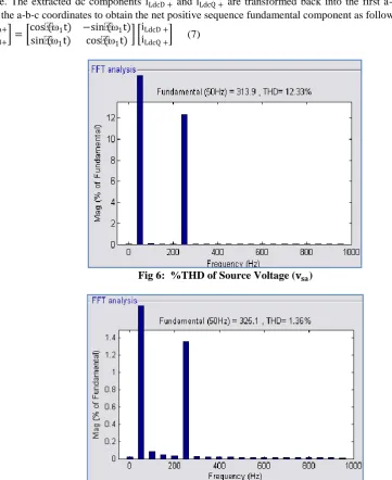
Fig 6: %THD of Source Voltage (𝐯𝐬𝐚)
Fig 7. %THD of Load Voltage (𝐯𝐥𝐚 ) After Compensation
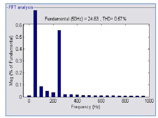
Fig 9. %THD of Source Current (𝐢𝐬𝐚) During Total Source Current Harmonics only
Fig 10. %THD of Source Current (𝐢𝐬𝐚) During the Mitigation of Total Source Current
Harmonics and Negative Sequence Components Only
Fig 11 %THD of Source Current (𝐢𝐬𝐚) During the Mitigation of Total Source Current Harmonics,
Where the real and reactive decomposition of the positive sequence fundamental frequency current (iL1Ra +, iL1Xb +) can be easily made from the d-q frame, thus the a-b-c coordinates of the real and reactive
components at the fundamental frequency can be evaluated as detailed in the following:
iL1Rα+ iL1Rβ+ =
cos(ω1t) −sin(ω1t) sin(ω1t) cos(ω1t)
0
iLdcQ + (8)
iL1Xα+ iL1Xβ+ =
cos(ω1t) −sin(ω1t) sin(ω1t) cos(ω1t)
iLdcD +
0 (9)
iL1Ra + iL1Rb + iL1Rc +
= 2 3 1 0 −1 2 3 2 −1 2 − 3 2
iL1Rα+
iL1Rβ+ (10)
iL1Xa + iL1Xb + iL1Xc +
= 2 3 1 0 −1 2 3 2 −1 2 − 3 2
iL1Xα+
iL1Xβ+ (11)
Similarly for a negative sequence, a fundamental component can be extracted by rotating the frame in the opposite direction, i.e., transformation to the two- phase stationary frame using eqn. (2) after executing the following transformation.
iLd − iLq − =
cos(ω1t) −sin(ω1t) sin(ω1t) cos(ω1t)
iLα
iLβ (12)
Then extracting the dc quantities by a LPF in a similar fashion. The dc quantity would amount to the negative sequence component of the current due to unbalanced voltage at PCC or the unbalanced load condition. The dc components so extracted, iLdcD − and iLdcq − are transformed back into a-b frame and then into a-b-c
coordinates to obtain the negative sequence fundamental components as follows:
iL1α− iL1β− =
cos(ω1t) sin(ω1t) −sin(ω1t) cos(ω1t)
iLdcD − iLdcQ − (13)
iL1a+ iL1b+ iL1c+
= 2 3 1 0 −1 2 3 2 −1 2 − 3 2
iL1α−
iL1β− (14)
Thus, for selective compensation, the above decomposed components can easily be used.
C. Control Scheme
Fig 3 shows the flow of various control signals and the control scheme based on the various decomposed components. The control scheme depicted in Fig 3 also incorporates the command for keeping the average dc bus voltage at the back to back VSIs constant or to control it within given limits. The command for the desired compensation of the three-phase supply reference currents (isa∗ , isb∗ and isc∗ ) are derived by taking the difference
of the load current and the decomposed components using the SRF theory and the nonconforming currents, which need to be compensated. The desired compensation source reference currents are compared to the sensed supply currents (isa, isband isc) and are given to a hysteresis current controller to generate the switching signals
to the switches of the shunt APF, which makes the supply currents follow its reference values. For the four-leg VSI shunt APF of three-phase four-wire UPQC, the source neutral current is compensated to follow a reference signal of zero magnitude by switching the fourth leg of the VSI, through the hysteresis controller. By doing this, the supply neutral current can be eliminated.
D. Priority Revolver and Gain Scheduler
This section describes the calculation of the gains (Kw , Kx ,Kn, Kh) according to the priority assigned
to the components needs to be compensated. The level of priority decides the depth of the compensation desired by the system, keeping in view the overloading of the shunt APF by adjustment of the gains Kw , Kx ,Kn and Kh
in reverse order, i.e., a component with a higher priority for its compensation would have a lower gain in the ratio of its priority. The priority of the compensation is fixed on the basis of the severity of ill effects of these decomposed components on the power system. In the scheme for the shunt APF of the UPQC, the first preference has been assigned to the harmonics generated by customers, the total source current harmonics and subsequently the gains of the negative sequence and reactive components are computed, keeping in view the interests of both the consumers and the utility. If it is assumed that the compensation capacity of the shunt APF of the UPQC is limited to 40% of the total load power, then the maximum value of the sum of the different RMS load current components, which can be compensated for, are given as Maximum of
V.
RESULTS AND DISCUSSION
The three-phase four-wire UPQC system and the control strategy of the UPQC are modeled using the MAT- LAB/SIMULINK enviournment. The load under consideration is a combination of the balanced linear lagging power factor loads and a three-phase diode bridge rectifier with a resistive load on dc side. The unbalance has been created by opening the circuit breaker of phase 'b'. A distortion in the utility voltage is introduced deliberately by injecting 5th (12.30%) order voltage harmonics along with the fundamental.
Fig. 4 shows the dynamic performance of the proposed UPQC system under varying load conditions. To visualize the shunt APF and series APF performances individually, both of these are put into operation at different instances of time. The shunt APF is switched on at t=0.05 sec. The first priority of the shunt APF is to compensate for the customer generated harmonics. Therefore, until t=0.15 sec, the source currents have levels of distortion that are similar to those present in the source voltages as shown in Fig 5(b). The THD in the source voltage is 12.33%, while during the compensation of customer generated harmonics only, the source current THD is 12.31%. This confirms the similar level of distortion in the source current as present in the source voltage. Hence, during the mitigation of customer generated harmonics, the non-linear load behaves as a linear load and the customer is not penalized for distorted supply.
The next priority is the compensation of the total source currents harmonics only. Fig. 4(d) shows that the source currents are balanced and sinusoidal, from t= 0.15 to t=0.18sec, even under distorted source voltages. The load becomes unbalanced at t=0.18 sec, by switching off the circuit breaker in phase 'b', as depicted in Fig. 4(e) and Fig. 5(a).Until t=0.24 sec, the shunt APF is only compensating the harmonics of the source currents, hence the source currents are sinusoidal but unbalanced, as shown in Fig. 4(e). They are also lagging w.r.t source voltages in each phase as shown in Fig. 5(b). The next priority of the shunt APF is load balancing, hence, the shunt APF starts compensating the negative sequence components of source currents from t=0.24 sec onwards. Fig. 4(e) shows that the source currents are balanced and sinusoidal after t=0.24 sec onwards, but that they are still lagging w.r.t source voltages in each phase as shown in Fig. 5(b). The last priority of the shunt APF is reactive power compensation, hence the source currents are sinusoidal, balanced and in phase with the corresponding phase voltages, as shown in Fig. 5(b). Fig. 4(e) shows that from t=0.15 sec to t=0.40 sec, the load currents become unbalanced; hence a neutral current flows as shown in Fig. 4(i).The THD of load voltage with and without compensation and source current during mitigation of different components are shownin Fig.6
VI.
CONCLUSION
A new current decomposition technique, based on frequency domain and SRF theory, with indirect current control and reduced number of current sensors for prioritized selective compensation of different power qualities and their combi- nations has been investigated for the shunt APF of three- phase four-wire UPQC. A control strategy based on SRF theory is applied for the control of the series APF of UPQC. The observed performance of the UPQC has demonstrated the ability of the proposed control technique to selectively compensate the customer generated harmonics, the total source current harmonics, unbalanced loading, reactive power and voltage harmonics, based on priority to respect the limited power capacity of VSIs employed for the shunt and series APFs. In addition to this, by mitigation of customer generated harmonics only, the responsibility of the utility and customers at the PCC is attributed. It is also observed that the proposed control scheme has a fast response and is able to maintain the voltage and current harmonics levels, thus conforming to IEEE-519 standards. Further, the applied control scheme is able to self-support the dc bus voltage of back to back connected VSIs of the UPQC. The control scheme of shunt APF has the advantage of flexibility in the selection of the power quality indices for which the reference may be computed. In addition to this the shunt APF compensates the current based distortions even under distorted utility voltages, hence the operation of shunt and series APF are independent of each other. In case of a voltage sensitive load, the series APF may be switched on to mitigate the voltage harmonics present in the load voltages.
APPENDIX
The system parameters used are as follows:
Supply voltage and line impedance: 415V L-L, f=50 Hz, Rs=0.1 , Ls=0.05mH
Ripple Filter: R=7 , C=5µF DC bus capacitance: Cdc=3000µF
DC bus voltage of UPQC: Vdc=600V
Series Transformer: 250KVA, 1.1KV/5.5KV
REFERENCES
[1]. A. Ghosh and G. Ledwich, Power Quality Enhancement Using Custom Power Devices, Kulwer International Series in Engineering and Computer Science, 2002.
[2]. N. G. Hingorani, “Introducing custom power” in Proc. IEEE Spectrum, Vol. 32, pp. 41-48, Jun.1995. [3]. A. Cetin, H.F. Bilgin, A. Acik, T. Demirci, K.N. Kose, A. Terciyanli, B. Gultekin, N. Aksoy, B.
Mutluer, I. C¸ adirci, M. Ermis, K. Ongan, and N. Akinci , “Reactive power compensation of coal conveyor belt drives by using D-STATCOMs” in Proc. IAS, pp.1731-1740, 2007.
[4]. M. J. Newman, D. G. Holmes, J.G. Nielsen, and F. Blaabjerg, “A dynamic voltage restorer (DVR) with selective harmonic compensation at medium voltage level” IEEE Trans. Ind. Appl., Vol. 41, pp.1744-1753, Nov./Dec. 2005.
[5]. K. H. Kwan, P. L. So, And Y. C. Chu, “A harmonic selective unified power quality conditioner using MVR with kalman filters” in Proc. IPEC, pp.332-337, 2007.
[6]. M. J. Newman and D. G. Holmes, “A universal custom power conditioner (UCPC) with selective harmonic voltage compensation” in Proc. IECON, Vol. 2, pp. 1261-1266, 2002.
[7]. H. Akagi, Y. Kanazawa, and A. Nabae, “Generalized theory of the instantaneous reactive power in three-phase circuits” in Proc. IEEE and JIEE IPEC, pp. 821-827, 1983.
[8]. Y. Komastu and T. Kawabata, “Experimental comparison of p-q and extended p-q methods for active filter” in Proc. EPE, Vol. 2, pp. 2.729- 2.734, 1997.
[9]. M. Depenbork and V. Staut, “The FBD-method as tool for compensating total non-active currents” in Proc. IEEE Harmonics and Quality of Power, pp.320-324, 1998.
[10]. L. S. Czarnecki, “Orthogonal decomposition of the currents in a 3-phase nonlinear asymmetrical circuit with voltage source” IEEE Trans. Instrum. Meas., Vol. 37, No. 1, pp. 30-34, Mar. 1998. [11]. F. P. Marafao, S. M. Deckmann, J. A. Pomilio, and R. Q. Machado, “Selective disturbance
compensation and comparisons of active filtering strategies” in Proc. IEEE Harmonics and Quality of Power, pp. 484-489, 2002.
[12]. B. Singh, V. Verma, and J. Solanki, “Neural network-based selective compensation of current quality problems in distribution systems” IEEE Trans. Ind. Electron., Vol. 54, No. 1, pp. 53-60, Feb. 2007. [13]. H. Karimi, M. Karimi-Ghartemani, M. R. Iravani, and A. R. Bakhshai, “An adaptive filter for
synchronous extraction on harmonics and distortions” IEEE Trans. Power Del., Vol. 18, No. 4, pp. 1350-1356, Oct. 2003.
[14]. B. Singh and V. Verma, “Selective, compensation of power-quality problems through active power filter by current decomposition” IEEE Trans. Power Del., Vol.23, No.2, pp.792-799, Apr. 2008. [15]. B. Singh and P. Venkateswarlu, “A simplified control algorithm for three phase four-wire unified
power quality conditioner” Journal of Power Electronics, Vol. 10, No.1, Jan. 2010.
[16]. K. Srinivasan “On separating customer and supply side harmonics contributions” IEEE Trans. Power Del., Vol. 11, pp. 1003-1012, Apr.1996.
[17]. S. K. Jain, P. Agarwal, and H. O. Gupta, “A control algorithm for compensation of customer-generated harmonics and reactive power” IEEE Trans. Power Del., Vol. 19, No. 1, Jan. 2004.
[18]. S. K. Jain, P. Agarwal, H. O. Gupta, and G. Agnihotri, “Modeling of frequency domain control of shunt active power filter using MATLAB Simulink and power system block set,” in Proc. ICEMS, Vol. 2, pp.1124- 1129, 2005.