Review of Rectangular Microstrip Patch Antenna with
Various Shape Slot for X-Band and KU-Band Application
1
Gaurav Goyal,
2Dr. Dheeraj Bhardwaj
1Govt. Polytechnic College, Tonk, Rajasthan, India 2Physics Department, BIT Mesra, Jaipur, Rajasthan, India
Abstract
In this rapid changing world high mobility necessity for a wireless telecommunication device and for high resolution mapping for radar communication, a small and light weight compact microstrip antenna has been playing a key role for wireless service requirements. This paper presents a literature survey of dual band rectangular patch antenna for X-band and KU-band application with variety of slots. In this paper we also discuss the basics of micro strip antenna, various slotted design model and antenna parameters. A rectangular microstrip patch antenna consist having different slot has been reviewed. All antenna has different area and different path length which effects the gain and radiation properties.
Keywords
Microstrip Antenna, Patch Width, Patch Length, Slot Design
I. Introduction
The study on microstrip patch antennas has made a great progress in the recent years. Compared with the conventional antennas, microstrip patch antennas have more advantages and better prospects. In this era of next generation networks we require high data rate and size of devices are getting smaller day by day.
For success of all the wireless applications we need efficient and
small antenna as wireless is getting more and more important in our life. This being the case, portable antenna technology has grown along with mobile and cellular technologies. Microstrip
antennas (MSA) have characteristics like low cost and low profile
which proves Microstrip antennas (MSA) to be well suited for Wirless application systems. A Microstrip patch antenna consists of a radiating patch on one side of a dielectric substrate which has a ground plane on the other side. The patch is generally made of conducting material such as copper or gold and can take any possible shape.
The dielectric substrate used is FR4 Glass Epoxy with 4.4 dielectric constant. The height of the substrates is constant i.e. 1.6 mm. This paper presents a rectangular patch which has application in
X-band and KU-band. The X-band and Ku-Band defined by an
IEEE standard for radar applications and satellite engineering with frequencies that ranges from 8.0 to 12.0 GHz and 12.0 to 18.0 GHz respectively. The X band is used for short range tracking, missile guidance, marine, radar and air bone intercept. Especially it is used for radar communication ranges roughly from 8.29 GHz to 11.4 GHz. X bands are often used in modern radars. The shorter wave length of the X band allow for higher resolution imagery
from high-resolution imaging radars for target identification and
discrimination.
II. Antenna Design
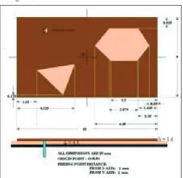
The conventional patch antenna is of rectangular shape having size 10mmX6mm for all antenna presented in this paper. The dielectric constant of all patches is 4.4 and loss tangent is 0.025. The probe feed radius is 0.5mm with substrate thickness of 1.6mm. BipaDatta
et al. presented paper in 2012 on A Printed Microstrip Antenna [1] having a single layer, single feed compact slotted patch antenna.
There are two different slots on the modified patch. The first one
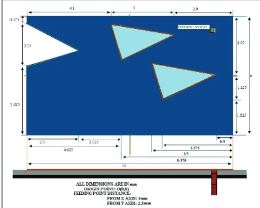
is the combinations of two triangular and another rectangular slot at the upper right corner and rest is bilateral triangle at the lower left corner from the conventional microstrip patch antenna. This patch has an metal area of 51.89%. Bipa Datta et al. presented a paper in 2012 on Multi-Band Microstrip Slotted Patch Antenna for Application in Microwave Communication [2]. They have cut two equal slots which are the combinations of one triangular and another rectangular slot at the upper right and lower left corner from the conventional microstrip patch antenna. The metal area of the patch is 51.11%. BipaDatta et al. presented a paper in 2012 on Monopole Slotted Patch Antenna for Microwave Communication [3]. They have cut three equal slots which are same hexagonal structure at the upper right, upper left, lower left corner and a circle at the center from the conventional microstrip patch antenna. This patch has metal area of 48.67%.Supria Jana et al. presented a paper in 2012 on Design Of An Unequal Arrow Based Printed Antenna For Radar Applications [4]. They have cut two triangular and one unequal shaped slot located from the conventional microstrip patch antenna. This patch has metal area of 46.74%. Supriya Jana et al. presented a paper in 2013 on Single Layer Monopole Hexagonal Microstrip Patch Antenna for Satellite Television[5]. They have cut two equal slots which are the combinations of two triangular and one rectangular slot at the upper right and lower left corner and middle point symmetrical Y-junction slot located from the conventional microstrip patch antenna. This patch has 43.45% metal area.
III. Results
Communication [3] which is thoroughly simulated in this paper. Resonant frequency has been reduced drastically by cutting three equal slots. Simulated antenna size has been reduced by 51.33% with an increased frequency ratio 1.392 when compared to a Conventional microstrip patch antenna. They have achieved gain of simulated 3.50 dBi at 9.75GHz and -0.79 dBi at 13.57GHz and beamwidth of simulated 162.960 at 9.75GHz and 123.090 at 13.57GHz and bandwidth of simulated 787.57MHz at 9.75GHz and 1.42GHz at 13.57GHz.Supria Jana et al. presented a paper in 2012 on Design of an Unequal Arrow Based Printed Antenna For Radar Applications [4] which represents an unequal arrow based printed antenna for many kind of wireless communication applications. Resonant frequency has been reduced drastically by cutting two triangular and one unequal shaped slot. They have achieved gain of simulated 3.73 dBi at 9.40635GHz and 0.33 dBi at 13.3046GHz and beam width of simulated 136.1890 at 9.40635GHz & 131.270 at 13.3046GHz of the printed antenna and bandwidth of simulated 418.58 MHz at 9.40GHz and 748.9MHz at 13.3046GHz. Compared to a conventional microstrip patch antenna, simulated antenna size has been reduced by 53.26% with an increased frequency ratio of 1.366. Supriya Jana et al. presented a paper in 2013 on Single Layer Monopole Hexagonal Microstrip Patch Antenna for Satellite Television [5] which is thoroughly simulated in this paper. Resonant frequency has been reduced drastically by cutting two equal slots. They have achieved gain of simulated 3.19 dBi at 9.12GHz and 0.62 dBi at 13.71GHz and beam width of simulated 162.910 at 9.12GHz and 64.470 at 13.71GHz and bandwidth of simulated 535.3 MHz at 9.12GHz and 1.4978GHz at 13.71GHz. Compared to a conventional microstrip patch antenna, simulated antenna size has been reduced by 56.55% with an increased frequency ratio of 1.5034.
IV. Conclusion
This paper presents a literature survey of dual band rectangular patch antenna for X-band and KU-band application with variety of slots. After study of various research papers sit concluded thatdecreasing in area causes increasing in frequency ratio. And as area decrease, At frequency f1 gain increases and bandwidth decreases but at frequency f2 gain decreases and bandwidth increases. As Path length increases, gain increases. Area increment causes good radiation pattern and beam width increment.
V. Acknowledgement
The authors express their sincere thanks to Professor Deepak Bhatnagar for providing the simulation facilities at their research laboratory.
Refrences
[1] Bipa Datta, Arnab Das, Samiran Chatterjee, Moumita Mukherjee, Santosh Kumar Chowdhury “A Printed Microstrip Antenna for RADAR Communication” IOSR Journal of Electronics and Communication Engineering (IOSR-JECE). Vol. 3, Issue 5, pp. 01-04, 2012.
[2] Arnab Das, BipaDatta, Samiran Chatterjee, Bipadtaran Sinhamahapatra, Supriya Jana, Moumita Mukherjee, Santosh Kumar Chowdhury,“Multi-Band Microstrip Slotted Patch Antenna for Application in Microwave Communication,” International Journal of Science and Advanced Technology, Vol. 2, Issue 9, pp. 91-95, 2012.
[3] “BipaDatta, Arnab Das, Samiran Chatterjee, Moumita Mukherjee, Santosh Kumar Chowdhury,“Monopole Slotted Patch Antenna for Microwave Communication”, International
Journal of Scientific and Research Publications, Vol. 2, Issue
11, 2012, [Online] Available: http://www.ijsrp.org
[4] Supriya Jana,“Design of an Unequal Arrow Based Printed Antenna for Radar Applications”, ECE Department under West Bengal University of Technology, West Bengal, India. International Journal of Engineering Science and Technology (IJEST).
[5] Supriya Jana, Bipadtaran Sinhamahapatra, Sudeshna Dey, Arnab Das, BipaDatta, Moumita Mukherjee, Santosh Kumar Chowdhury, Samiran Chatterjee,“Single Layer Monopole Hexagonal Microstrip Patch Antenna for Satellite Television”, International Journal of Soft Computing and Engineering (IJSCE), Vol. 2, Issue 6, 2013.
Antenna Design
Fig. 1: Geometry of Rectangular Conventional Antenna
Configuration
Fig. 3: Reflection Coefficient Curve of Simulated Antenna of a
Printed Microstrip Antenna for Radar Communication
Fig 4: simulated antenna of Multi-Band Microstrip Slotted Patch Antenna for Application in Microwave Communication
Fig. 5: Reflection Coefficient Curve of Multi-Band Microstrip
Slotted Patch Antenna for Application in Microwave Communication
Fig. 6: Simulated Antenna of Monopole Slotted Patch Antenna for Microwave Communication
Fig. 7: Reflection Coefficient Curve of Monopole Slotted Patch
Antenna for Microwave Communication
Fig. 9: Reflection Coefficient Curve of Design of an Unequal
Arrow Based Printed Antenna for Radar Applications Fig. 10: Simulated Antenna of Single Layer Monopole Hexagonal Microstrip Patch Antenna for Satellite Television
Fig. 11: Reflection Coefficient Curve of Single Layer Monopole
Hexagonal Microstrip Patch Antenna for Satellite Television
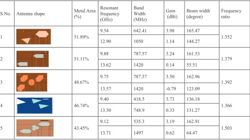
Table 1: Comparison of Rectangular Patch Antenna with Various Slot
S.No. Antenna shape Metal Area(%) Resonant frequency (GHz)
Band Width (MHz)
Gain
(dBi) Beam width (degree) Frequency ratio
1 51.89% 9.54 642.41 3.98 165.47 1.352
12.90 1050 1.14 144.27
2 51.11% 9.88 787.57 3.24 161.53 1.379
13.62 1420 0.14 55.51
3 48.67% 9.75 787.57 3.50 162.96 1.392
13.57 1420 -0.79 123.09
4 46.74% 9.40 418.5 3.73 136.18 1.366
13.30 748.9 0.33 131.27
5 43.45%
9.12 535.3 3.19 162.91
Gaurav Goyal received his B.E. degree in Electronics and communication from Birla Institute of Technology, Mesra, Ranchi, in 2014. Currently, He is a Lecturer in Electronics Department at Government Polytechnic collegeTonk, Rajasthan.His research interests include wireless communication, specifically microwave comm. and microstrip Patch antenna for modern wireless communication, Space Communications and Satellite Navigation. Along with these he also likes Electronic Devices and Circuits.
Dr. Dheeraj Bhardwaj received the
Ph.D. degree in the field of Microstrip
Patch Antennas from the University of Rajasthan, Jaipur, in 2011. Currently, he is an Assistant Professor of the Department of Physics at Birla Institute of Technology, Mesra, Jaipur Campus. He has published more than Sixty Research Papers in the reputed International Journals, National Journals and Conferences. He
has guided more than Twenty final year research projects of