e-ISSN: 2278-067X, p-ISSN: 2278-800X, www.ijerd.com
Volume 10, Issue 3 (March 2014), PP.76-83
Static Structural Analysis of Boiler Shell with Riveted Joints
Using CAE Tool’s
Aslam kha Kausar kha Pathan
1, Sheikh Kasim Sheikh Rauf
2,
Nikhil V. Nandanwar
3Student1,2-Mechanical Engg Dept. Dr N.P. Hirani Institute Of Polytechnic Pusad Professor3- Mechanical Engg Dept. Dr N.P. Hirani Institute Of Polytechnic Pusad
Abstract:-This paper deals with the stress analysis of boiler shell with riveted joints. By using finite element method, a stress analysis has been carried out under the application of pressure at the inner surface of boiler shell. Von-Mises stresses and maximum shear stresses are found. These stresses are compared with analytical results. Using the two materials, structural steel and aluminum alloy, stress values have been compared for same working conditions. It is found that structural steel is safer as compared to aluminum alloy at the same working conditions. Modeling has been done by Pro-E and analysis of riveted joint has been done by ANSYS (Workbench) with a version 14.5.
I.
INTRODUCTION
Rivets are used to make permanent fastening between the plates such as in bridges, tanks and boiler shells. The riveted joints are widely used for joining light metals. The boiler and pressure vessels are cylindrical in shape and withstand high internal pressure. The cylindrical pressure vessel is identified by two dimensions, the length and diameter. The cylinders are made from plates and whole length of shell may not be obtained from single sheet. Therefore, cylindrical sections are obtained by bending sheets and joining edges by riveted joint. The sections are then joined together by another riveted joint along circumference. Thus there are two types of joints longitudinal and circumferential. The longitudinal joint bears hoop stress (σh) and circumferential joint bears longitudinal stress (σl). As σh= 2 σl, the longitudinal joint will have to be two times as strong as circumferential joint. Therefore, longitudinal joints are made butt joints whereas the circumferential joints are mode as lap joints. Farah et al. developed software for designing and analyzing rivets of boiler shells as an example to use rivets in industry [1]. Until recently the primary analysis method had been hand calculations and empirical curves. David Heckman studied finite element analysis of pressure vessel using ANSYS [2]. William Barnet concluded that the difference between the diameter of rivet hole and of the rivet should vary with the size of rivet [3]. Nidhi et al. showed burst pressure prediction of pressure vessel using FEA. They proposed various types of finite element methods used for the calculation of burst strength of pressure vessel [4]. Kale et al. studied analysis of adhesively bonded riveted joints [5]. Hossein et al. studied parameters including squeeze force, rivet length, rivet diameter and hole diameter tolerance associated with a riveting process that directly affects the quality of rivets [6- 7]. Elzbieta et al. showed influence of technological imperfections on residual stress fields in riveted joints [8]. Gutman et al. purposed a method for determining the critical time of stability loss in thin-walled high-pressure vessels subjected to uniform corrosion from the inside [9]. Masayuki et al. studied the failure pressure of pipe with wall thinning using three-dimensional elastic–plastic finite element analyses [10]. A number of analyses have been performed on thin pressure vessels and riveted joints. But static structural analysis of boiler shell with riveted joints (which is designed on the basis of thin pressure vessel theory) using ANSYS has not been studied yet. By using finite element method, a stress analysis has been carried out under the application of pressure at the inner surface of boiler shell. Using the two materials, structural steel and aluminum alloy, stress values have been compared for same working conditions.
II.
PROBLEM MODELLING
A double riveted lap joint has been analyzed. Geometry of the present problem is: Diameter of the cylinder = 1500 mm.
Pressure= 2 N/mm2 Pitch = 105 mm
Thickness of the cylinder = 22 mm as shown in figure1. Maximum principle stress σ1=90 MPa
= 87.64 MPa
Maximum Shear Stress = (σ1-σ3)/2 =44 Mpa
Fig.1 Geometry of boiler shell with riveted joints using symmetry
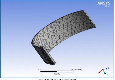
The problem is modeled in ANSYS workbench 14. Finite element mesh is generated for full assembly as shown in figure 2. The mesh refinement is carried out until the radial stresses at most of the inner and outer surface of the cylinder closely match with applied pressure and zero respectively
Fig. 2 Meshing of boiler shell
Table 1 Material Properties of Structural Steel and Aluminum Alloy for Boiler Shell
Property Structural steel Aluminum alloy
Young’s Modulus,(E) 2×10⁵ MPa 7.1×10⁴ MPa
Poisson’s Ratio 0.30 0.33
Tensile Ultimate
strength
460MPa 310 MPa
Tensile Yield strength 250 MPa 280 MPa
Compressive yield
strength
250 MPa 280 MPa
Density 7850kg/m3 2770 kg/m3
III.
RESULTS AND DISCUSSIONS
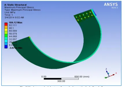
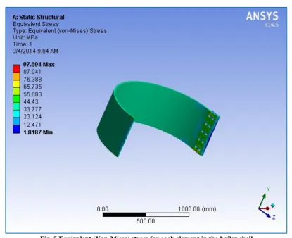
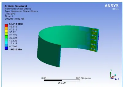
As shown in figure 5 minimum principle stress at most of the inner surface is 2.57MPa, which is in close agreement with the applied pressure at inner surface. Figure 5 shows the equivalent (Von-Mises) stress of the boiler shell for a pressure of 2MPa. The maximum stress is found to be 96.28 MPa which is at internal surface near the rivet heads as shown by red color, this includes local stress. Excluding local stress its value is 85.91 MPa which is in the close agreement with 87.64 MPa (analytical value). Maximum principle stress shown in figure 4 is 90.66 MPa (excluding local stress) and figure 7 show maximum shear stress 49.58 MPa (excluding local stress) are in close agreement with analytical results. Figures 7 show total deformation, andPossible reasons for variation might be the due to the assumption that loading is considered as surface loading in analytical calculation while it is taken on a bunch of nodes in ANSYS. Table 2 shows the comparison of analytical results and FEA results. Figures 8-10 show analysis of boiler shell with riveted joints using aluminum alloy. Results have been compared for different values of stresses for structural steel (shell as well as rivets) and aluminum alloy (shell as well as rivets) as shown in table 3. Results have also been compared at increasing pressure for structural steel and aluminum alloy as shown in Figure 11.
Fig. 4 Minimum principle stress for each element in the Boiler Shell.
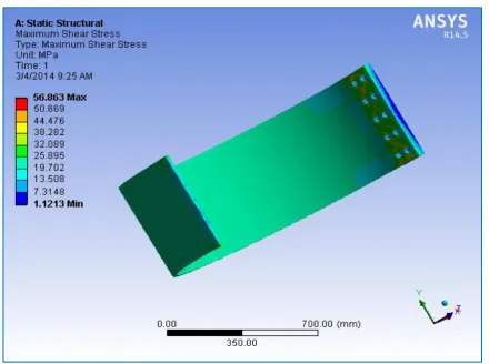
Fig. 6 Maximum shear stress for each element in the boiler shell.
Fig. 7 Total deformation for each element in the boiler shell.
Table 2 Comparison of Theoretical Results with FEA Software Results
S. No. Stress Theoretical Result (MPa) FEA Result (MPa)
(Excluding local stress 1 Maximum principle stress 90 90.66
2 Minimum principle stress 2 2.57
3 Von-Mises stress 87.64 85.91
Fig. 8 Equivalent (Von-Mises) Stress for each element in the boiler shell for aluminum alloy
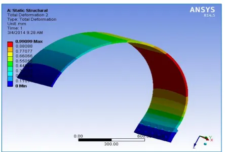
Fig.10 Total deformation for each element in the boiler shell for aluminum alloy
Table 3 Comparison of Results for Structural Steel and Aluminum Alloy
S. No. Parameters FEA results for
structural steel
FEA results for aluminum alloy 1 Equivalent von-Misses stress 96.28 MPa 100.46 MPa
2 Maximum shear stress 55.57 MPa 56.82 MPa
3 Total deformation 0.3434 mm 0.9463 mm
IV.
CONCLUSIONS
The following conclusions can be drawn from analysis:
1. The maximum Von–Mises stresses (including local stress) in structural steel as well as in aluminum alloy are less than as compared to their corresponding yield strengths as well as maximum tensile strength. The models presented here are safe and under permissible limit of stresses.
2. The results obtained are well in agreement with the analytical results.
3. Boiler shell with riveted joints made with structural steel is safer as compared to boiler shell made with aluminum alloy.
REFERENCES
[1]. Farah KamilAbid Muslim Dr. Essam L. Esmail, Computer aided design of rivets for Steam Boiler Shell Al-Qadisiya Journal for Engineering Sciences, Vol. 5, No. 4, 377-393, Year 2012.
[2]. David Heckman, Finite Element Analysis of Pressure Vessels, University of California, Davis Mentor: Gene Massion, Mark Greise Summer 1998
[3]. William Barnet Le Van, Riveted joints in Boiler shell, Read at the state meeting of institute, held Nov 19,1890.
[4]. NidhiDwivedi, Veerendra Kumar, Burst Pressure Prediction of Pressure Vessel using FEA, International Journal of Engineering Research & Technology (IJERT) ISSN: 2278-0181, Vol. 1 Issue 7, September – 2012
[5]. Kale Suresh, K.L.N.Murty&T.Jaynanda Kumar, Analysis of adhesively bonded single lap riveted joint using ANSYS International Journal of Mechanical and Industrial Engineering (IJMIE) ISSN No. 2231 –6477, Vol-2, Iss-4, 2012
[6]. Faisal Aman& S. HosseinCheraghi& Krishna K. Krishnan & Hamid Lankarani, Study of the impact of riveting sequence, rivet pitch, and gap between sheets on the quality of riveted lap joints using finite element method Springer-Verlag London Limited 2012
[7]. S. HosseinCheraghi, Effect of variations in the riveting process on the quality of riveted joints Springer-Verlag London Limited 2007
[8]. ElzbietaSzymczyk, Jerzy Jachimowicz, GrzegorzSławinski, AgnieszkaDerewonkoa, Influence of technological imperfections on residual stress fields in riveted joints Military University of Technology, ul. gen. SylwestraKaliskiego 2, 00-908 Warsaw, Poland
[9]. E. Gutman , J. Haddad , R. Bergman, Stability of thin-walled high-pressure vesselssubjected to uniform corrosion Department of Material Engineering, Ben Gurion University of the Negev, Israel, School of Engineering, Beer-Sheva , Israel