ISSN: 2278-067X, Volume 1, Issue 4 (June 2012), PP.53-63
www.ijerd.com
Performance of Smart and Flexible Parallel Concatenated
Turbo Codes for Wireless Sensor Networks
Revanesh.M
1, Sujatha D.Badiger
21
M.Tech Student, Communication system Engg. R V College of Engg. Bangalore-59
2 Assistant Professor, Dept. of Electronics & communication Engg. R V College of Engg. Bangalore-59
Abstract— with the energy and size constraint involved with the wireless sensor nodes it is very hard to implement
powerful Error control Coding (ECC) techniques like Turbo codes which have shown to be capable of performing near Shannon limit on every sensor node. In this article an adaptive approach for the implementation of this Turbo codes is proposed where in the soft decision iterative decoder implementation is shifted to the base station of the network and a turbo encoder and error correction circuit are implemented at the sensor nodes. The performance of proposed system was evaluated by increasing the number of communication hops and different interleaver sizes. This proposed approach enhances the reliability of network communication by increasing the energy efficiency of the system. The reliability of proposed systems decision with MAX-Log-MAP and Log MAP decoding algorithms is tested.
Keywords—ECC, Interleaver, MAP, Shannon limit, soft decision iterative decoder.
I.
INTRODUCTION
Design of channel coding always has a tradeoff between Energy efficiency and Bandwidth efficiency. Codes with lower data rate (i.e., bigger redundancy) can usually correct more errors while on the other hand codes with low data rate have a large overhead and are hence heavier on bandwidth consumption. If more errors can be corrected using a system then such a communication system can operate with lower Transmission power allowing transmission over long distances with lesser power, tolerating more interference and also allows the system to transmit at a higher data rate using even smaller size antennas which improves the Energy Efficiency of the system. Considering the practical applications of wireless sensor network it becomes very essential to address the challenges mentioned above for the design of channel coding in a wireless sensor network which has a serious effect on the performance of the system otherwise. One of the major applications involving use of Wireless Sensor Network is monitoring remote and isolated areas, collecting and processing information about some natural phenomenon like volcanic eruptions or some other high intensity activity from places with the least human activities, in such applications the channel state is expected to vary continuously owing to the dynamic changes in the environmental factors. Also the sensor nodes in these areas will experience high degree of wear and tear which destroys the continuity in the network operation at this stage it becomes really hard for the network to operate efficiently even when transmitting with maximum power, without strong error correction techniques. Using Automatic Repeat Request (ARQ) in such scenarios is proved to be inefficient because of the high number of retransmissions needed. Also use of ARQ techniques introduces considerable amount of delay in transferring the information from one part of the network to the other or to the base station. Also use of ARQ technique also has a serious of energy consumption from both transmitting and receiving nodes. Thus there is a strong need for a powerful Error Correction scheme .Some previous studies on simple Error Correction techniques like BCH, Reed-Solomlon and convolutional codes[1] reveals that the error correction capabilities of these codes are obtained at the expense of high redundancy in the transmitted data and also use of these coding techniques introduces considerable amount of delay in delivering the collected data packets from sensor node to base station [2] because of the coding and decoding process that run on each routing node in the network..
One of the alternative approaches is to improve the performance of such system a system can be the use of turbo codes which makes use of 3 simple ideas [3].
o Concatenation of codes (parallel or serial) which supports simple decoding
o Interleaving to provide better weight distribution
o Soft decoding to enhance the decoder decision and to maximize the gain from decoder iterations
but decoding is hard [4]. Also Compared to the node using plain ARQ without FEC the repetition code and the Turbo Code consume roughly 80% and 85% less energy, respectively [1]. Thus the high processing power requirements of turbo decoding structure makes it hard to be implemented on sensor node which have limited energy sources and space. Therefore considering the complexities involved in implementation of turbo codes an adaptive algorithm is proposed which proposes the implementation of turbo encoding scheme as shown in figure 1 along with the Error Correcting schemes at each sensor nodes while shifting the decoder implementation to the base station where enough processing power and space are available for its operation.
II.
TURBO
ENCODER
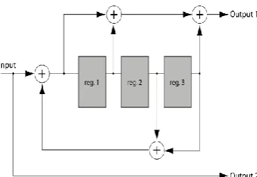
One of the most generally used turbo code configuration is the Parallel Concatenated Convolutional Code (PCCC) shown in Figure 1, which consists of two parallel concatenated encoders (RSC) as in figure 2 which generates a systematic output along with the encoder outputs, the parity bits and are generated from each of the recursive encoders using shift register set as shown in figure 2 in response to input m. [4]. The encoder here is designed as PCCC
with coding rate 1/3 for evaluating its performance. The input information sequence (composed of symbols drawn from an alphabet set {𝑑1, 𝑑2 ... 𝑑𝑁} of length N and emitted by the source), enter an encoder that generates code sequence C=
{ ……, }. Both source and code sequences are defined over a finite time index set K= {a finite set of integers, 𝑘}. The code symbol c𝑘 enters the digital modulator, performing a one-to-one mapping with its signals, or channel input symbols x𝑘⊆𝑋={𝑥1, 𝑥2, ..., 𝑥𝑀}. Then the channel symbol x𝑘 are transmitted over a stationary discrete memory less channel with output symbols y𝑘. An additive white Gaussian noise (AWGN) model with zero mean and variance 𝑁0/2 is considered. The encoder designed using smart and flexible compare and correct algorithm is built using the same procedure as mentioned above. At the source node this PCCC circuit is used for encoding data packets, while the PCCC circuits present on the routing nodes to the base station work as Detect-Correct circuits [11]. This function at the forwarding nodes is important, not only it can correct some error bits in the forwarded packets but it also monitors the error pattern occurring in the packets. If bursts of error occurred in the packet, the Detect-Compare circuit detects it and requests the previous routing node or source node to retransmit only the damaged part of the packet. At the forwarding nodes, the original data is extracted from the packet and re-encoded using the PCCC circuit. The outputs of the RSC encoders are compared with the parity bits in the received packet. This operation prevents highly corrupted packet from propagating through the network to the base station, where it could be undecodable and lost. Also it reduces the size of the retransmitted packets to be only size of the collided part of the packet when a near node transmits on the same packet transmission duration. The interleaver here is modeled as a block of variable size N. The first Recursive Systematic Convolutional encoder (RSC) reads serially data bits from the memory row-by-row, while the second RSC encoder reads the data symbol from the memory in random sequence through the interleaver block. The outputs of the RSC encoders are combined with the data sequence to form the output coded packet.The most influential parameter in the design of turbo codes is the Interleaver size which accounts for the improved performance of the turbo codes. The task of interleaver is to ―scramble‖ bits in a pseudo-random, predetermined fashion.
This serves two purposes [5].
o By providing an interleaved data to the second encoder two different outputs are produced which means that even if one codeword has low weight the other usually does not, which is beneficial for the performance of decoder.
o Corresponding to the scrambled input from interleaver the output will also be ―uncorrelated‖ from one another .this means the corresponding two decoders will gain more from information exchange.
Also an increase in the interleaver memory size with N increase the system reliability by reducing the bit error probability at the decoder output by a factor 1/N [6].
Figure.2 Recursive Systematic convolution encoder
III.TURBO DECODER
Figure 3.shows a schematic diagram of the iterative decoding procedure adopted by turbo codes which uses two ‗Soft-in-Soft-out‘ (SISO) component decoders. In a typical turbo decoding system two decoders operate iteratively and pass on their information to each other after each iteration. The soft output produced by these decoders adds up to the improvement in the performance of decoder. The first SISO decoder generates the soft output and subsequently extrinsic information (EI). The extrinsic information is interleaved and used by the second SISO decoder as the estimate of the a priori probability (APP). The second SISO decoder also produces the extrinsic information and passes it after de -interleaving to the first SISO decoder to be used during the subsequent decoding operation as shown in figure(4).
Figure. 3 Block diagram of iterative turbo decoder
Figure. 4 Parallel concatenated convolution decoder
is interleaved and used by the second SISO decoder as the estimate of the APP. The second SISO decoder also produces the extrinsic information and passes it after deinterleaving to the first SISO decoder which is used by subsequent decoding operations. MAP and SOVA are two important soft decisions decoding algorithm, scaling the extrinsic information further helps in improvement of the performance of the system towards the Shannon‘s limit. The MAP algorithm is a Maximum Likelihood (ML) algorithm and the SOVA is asymptotically an ML algorithm at moderate and
high SNR. While on the other hand SOVA finds the most
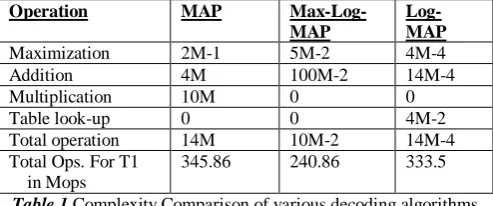
probable information sequence to have been transmitted given the code sequence. That means the MAP algorithm minimizes the bit or symbol error probability, where as SOVA minimizes the word error probability. Infor mation bits returned by the MAP algorithm need not form a connected path through the trellis while for SOVA it will be a connected path. However the MAP algorithm is not easily implementable due to the complexities involved [6]. Some of the modified approaches of MAP decoding algorithm are: Max-Log-MAP algorithm where computations are easier to implement than the MAP and Log-MAP algorithm avoids the approximations in the Max-Log-MAP algorithm through the use of simple correction function at each maximization operation and thus its performance is close to that of MAP algorithm. Table.1 shows the comparison of complexities involved during different decoding methods per unit frame for (n, k) convolutional code with memory order v.
Operation MAP Max-Log-MAP
Log-MAP
Maximization 2M-1 5M-2 4M-4
Addition 4M 100M-2 14M-4
Multiplication 10M 0 0
Table look-up 0 0 4M-2
Total operation 14M 10M-2 14M-4
Total Ops. For T1 in Mops
345.86 240.86 333.5
Table 1.Complexity Comparison of various decoding algorithms
The turbo decoding process in general can be explained as follows: Encoded information sequence is
transmitted over an AWGN channel and a noisy received sequence is obtained. Each decoder calculates Log-Likelihood Ratio (LLR) for the data bit as
L ( ) = log
LLR can be decomposed into 3 independent terms, as L ( ) = + + (2)
Where is the a-priori information of , is the channel measurement, and is the extrinsic
information exchanged between the constituent decoder. Extrinsic information from one decoder becomes the a-priory information for the other decoder at the next decoding stage. The MAP algorithm seek the most likely data sequence whereas SOVA,which is a modified version of Viterbi algorithm, seeks for the most likely connected path through the encoder trellis. At high SNR the performance of MAP and SOVA are almost the same. However at low SNR MAP algorithm is superior to SOVA by 0.5 dB or more. The MAP algorithm and its simplified versions Log MAP and Max-Log-MAP algorithms are explained below.
A. MAP Algorithm
The MAP algorithm is an optimal but computationally complex SISO algorithm. The Log-MAP and Max-Log-MAP algorithms are simplified versions of the MAP algorithm.MAP algorithm calculates LLRs for each information bits as
(3)
Where α is the forward state metric, β is the backward state metric , γ is the branch metric, and is the trellis state at trellis time k. k is expected to vary from 1 to N where N is the information bits in one data frames.
The forward state metrics is calculated as,
= (4)
Similarly, the backward state matrices are calculated by a backward recursion from trellis time k=N to k=1 as
= ( 5)
Branch metrics are calculated for each possible trellis transition as
( )=
(1)
(2)
B.The Log-MAP Algorithm
To avoid the complex mathematical calculations of MAP decoding, computations can be performed in the logarithmic domain. Furthermore, logarithm and exponential computations can be eliminated by following approximation
Max*(x, y) ln( )= max(x, y) + log(1+ )
C.The Max-Log-MAP Algorithm
The correction function = log (1 + ) in the max*(.) operation can be implemented in different ways. The Max-Log-MAP algorithm simply neglected the correction term and approximation the max*(.) operator as
Ln( ) max(x, y)
at the expense of some performance degradation. The performance degradation due to this simplification is about 0.5 dB compared to Log-MAP algorithm.
IV. METHODOLOGY
The design implementation is based on a simple strategy that involves combining simple codes in parallel fashion so that each part of the code can be decoded separately with comparatively less complex decoder structure ,this strategy can be called as ― Divide and Conquer Strategy‖. The important aspect of design in this strategy is the decoder implementation is shifted to base station where in enough power is present for the decoder implementation while running the PCCC circuitry in the wireless sensor nodes for encoding the data packets received at the sensor node, If the node is a forwarding node then the circuit runs as Error Detection and Correction circuit as shown in figure 5.
A. Detect and Correct Algorithm
Considering the wireless sensor network to have multiple nodes between the source node and the base station, at each forwarding node the received data packet is processed to get the parity bits and once the parity bits are received these parity bits are compared with the outputs of RSC encoder at that node using the Detect and Correct circuit. The first RSC encoder reads data bits serially from the memory row by row while the second RSC encoder reads data from the memory after it is being passed through random interleaver. At forwarding nodes i.e. nodes where the detection and correction algorithm are functional the memory is filled with the uncoded data stream extracted from the received packet, the two RSC encoders here operate in the same way as in the PCCC encoding circuit and generate two outputs each from one Encoder which will be given to the Detection-Correction circuit as shown in figure (5). The Detection-Correction algorithm [11] runs with the following steps:
Step 1: If the node is a source node then fill the interleaver memory with the uncoded message (data) which is then combined with the outputs of RSC encoder to form the coded data which will be passed on to the rest of the network as coded data.
Step 2: If the node is a forwarding node then fill the interleaver with the uncoded data which is extracted from the received coded sequence and compare it with the generated output from the two RSC encoders which are present at that node.
Step 3: Compare the output generated from the two RSC encoder with the Parity bits from the received vector. If the compared bits are identical then compare the next set of data and continue the step until the last set of packet in the memory are transmitted. Else
1) If consequent errors are detected with length K-1 which represents the length of delay line return K-1 bits to the interleaver memory flip the data bits then back to step 3.
2) If consequent errors detected are of smaller length than K-1, then just flip the bits which are different and jump to step 3.
3) Else if consequent error length is equal to K-1 and the number of retries to correct the errors has been exceeded then ask for retransmission from this point of the packet to the end of the packet.
Step 4: After running the algorithm on the entire symbol in the memory, transmit the processed packets to the next node in routing path.
Figure. 5 PCCC with Error Detection and Correction
V. EVALUATION
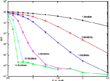
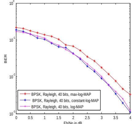
Using matlab a simulation environment is carried out to test the performance of turbo coded system, which is built using two recursive Systematic convolution encoders both having [13 15] code generation function as shown in the figure 2. The built system‘s performance is tested to check the dependency of the built system on various parameters. First the performance of simple turbo code with r=1/2 is evaluated keeping the interleaver memory size to be fixed to 65,536 for varying number of iterations. Figure 6 shows the BER performance of turbo system for different number of iterations. Interleaver design always plays a key role in the development of turbo codes and in order to show the effect of interleaver size a simulation was run keeping the number of decoder iterations to a constant value of 16 for different interleaver size. Figure 7 shows the BER vs. SNR performance for the system with different interleaver size.The systems performance always depends on the decoding algorithm employed in order to evaluate the systems. The system is evaluated for two different soft decision decoding algorithms i.e. MAP and SOVA. Figure 8 shows the BER performance of MAP and SOVA algorithms for variable frame size with fixed number of decoder iterations. Also the performance of different MAP decoding algorithms are evaluated keeping the interleaver memory size fixed with BPSK modulation, modeling the channel between the node to the base station as Rayleigh fading channel. The same evaluation performance is repeated modeling the channel between the nodes as AWGN channel with symmetric SNR. figure 9 and figure 10 shows the recorded performance of various MAP decoding algorithm for both AWGN and RAYLEIGH Fading channel keeping the interleaver memory size to a constant value of 40 and considering BPSK modulation .the test was repeated for various MAP decoding algorithm and the figure 9 and 10 shows the BER vs. SNR performance of Max-Log-MAP, constant Log MAP and Log MAP.
Figure. 6 BER vs Eb/No for a simple turbo code with rate =1/2 and 16 decoder iterations for different number of
Figure. 7 BER vs Eb/No for a simple turbo code with rate=1/2, L=65536 for different number of iterations
Figure. 8 Performance of turbo MAP and SOVA algorithm with variable frame size 3 decoding iterations
0 0.5 1 1.5 2 2.5 3 3.5 4
10-3
10-2
10-1
100
Eb/No in dB
BER
BPSK, Rayleigh, 40 bits, max-log-MAP BPSK, Rayleigh, 40 bits, constant-log-MAP BPSK, Rayleigh, 40 bits, log-MAP
Figure. 9 Performance of turbo codes in Rayleigh channel interleaver memory size =40 with BPSK modulation
circuit and the BER performance was recorded, next the same arrangement of figure (12) is again simulated with Detect and correct algorithm running in between nodes.
0 0.5 1 1.5 2 2.5 3 3.5 4 4.5
10-6
10-5
10-4
10-3
10-2
10-1
100
Eb/No in dB
BER
UMTS-TC, BPSK, AWGN, 40 bits, max-log-MAP UMTS-TC, BPSK, AWGN, 40 bits, constant-log-MAP UMTS-TC, BPSK, AWGN, 40 bits, log-MAP
Figure. 10 Performance of turbo codes in AWGN channel interleaver memory size =40 with BPSK modulation.
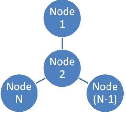
Figure. 11 Wireless sensor network
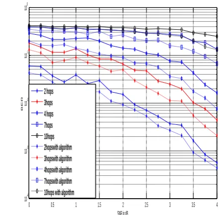
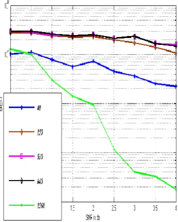
Figure (13) shows the comparison of results obtained from running the detect and correct algorithm (re-encode algorithm) and the one without it. In order to test the effect of interleaver size on this network a fixed arrangement of network is considered which has fixed number of hops between the source node and the base station and the simulation is again carried out for different sizes of interlever memory as shown in figure (14) and figure(15) by fixing the number of hops between the node and the base station.
0 0.5 1 1.5 2 2.5 3 3.5 4 10-4
10-3 10-2 10-1 100
SNR in dB
BER
2 hops 3hops 4 hops 7hops 10hops 2hopswith algorithm 3hopswith algorithm 4hopswith algorithm 7hopswith algorithm 10hops with algorithm
Figure. 13 BER Vs SNR with different number of communication hops
0 0.5 1 1.5 2 2.5 3 3.5 4
10-4 10-3 10-2 10-1 100
Eb/No in dB
BER
40
150
530
640
1560
Figure. 14 BER vs. SNR in dB for rate 1/3 turbo code with number of hops=3 for various interleaver size
Figure. 15 BER vs SNR for 4HOPS and different interleaver size
Figure. 16 comparisons of log map and max-log-map BER vs SNR with different number of hops
VI. CONCLUSION
REFERENCES
[1]. G. Balakrishnan, M. Yang, Y. Jiang, and Y. Kim, ―Performance Analysis of Error Control Codes for Wireless Sensor Networks,‖ Fourth Interna- tional Conference on Information Technology (ITNG‘07), pp. 876–879, Apr. 2007.
[2]. S. Benedetto, G. Montorsi, T. Agenzia, and S. Italiana, ―Design of parallel concatenated convolutional codes,‖ IEEE Transactions on Com- munications, vol. 44, pp. 591–600, 1996
[3]. A. J. Goldsmith and S. B. Wicker, ―Design challenges for energy constrained ad hoc wireless networks,‖ IEEE Wireless CommunicationsMagazine, pp. 8–27, 2002.
[4]. Daniel Schmidt, Matthias Berning, Norbert When ―Error Correction in Single-Hop Wireless Sensor Networks” Microelectronic Systems Design Research Group. University of Kaiserslautern, Communication survey, 2009, Germany.
[5]. F. Walther, ―Energy modelling of MICAz: A low power wireless sensor node,‖ Technical Report, University of Kaiserslautern, February 2006
[6]. S. L. Howard, C. Schlegel, and K. Iniewski, ―Error Control Coding in Low-Power Wireless Sensor Networks: When Is ECC Energy-Efficient?,‖ EURASIP Journal on Wireless Communications and Networking,vol. 2006, pp. 1–15, 2006.
[7]. A.M Viterbi ―Shannon theory concatenated codes and turbo coding‖ http:// oocs.donvblack.com/viterbi/index.html.1998
[8]. S. Lin and D. J. Costello,‖ Error Control Coding,‖ Second Edition. UpperSaddlRiver, NJ, USA: Prentice-Hall, Inc., 2004.
[9]. T. K. Moon,” Error Correction Coding”: Mathematical Methods andAlgorithms. Wiley-Interscience, 2005. [10]. C. Schlegel and L. Perez, ―Trellis and Turbo Coding”. Wiley-IEEE Press,2004.
[11]. N. Abughalieh, Kris Steenhaut, Ann Nowé ―Adaptive Parallel Concatenation Turbo Codes for Wireless Sensor Networks”
2011 International Conference on Communications and Information Technology (ICCIT), Aqaba
[12]. H. Soude, M. Agueh, and J. Mehat, “Towards an optimal reed solomon codes selection for sensor networks”. New York, New York, USA: ACMPress, 2009.
[13]. Sergio Benedetto “Design of parallel concatenated convolution codes” IEEE Transactions on Communications,vol. 44, no 5, May1996.
[14]. June Chen and Ali Abedi. ― Distributed Turbo Coding and Decoding for Wireless Sensor Networks” IEEE communication letters, vol. 15, NO. 2, feb. 2011.