Modeling and Stability Analysis of a DC-DC SEPIC
Converter by Employing Optimized PID Controller
Using Genetic Algorithm
Mirza Muntasir Nishat, Fahim Faisal and Md. Ashraful Hoque
Department of Electrical and Electronic Engineering
Islamic University of Technology, Board Bazar, Gazipur-1704, Bangladesh Email: [email protected] , [email protected] , [email protected]
Abstract— This paper presents an investigation on closed loop stability of SEPIC (Single-Ended Primary Inductor Converter) converter by employing an optimized PID controller where the parameters are tuned by Genetic Algorithm (GA). Genetic Algorithm is a stochastic algorithm inspired by natural evolution and is extensively used as an optimization technique in power electronics in recent years. State Space Average method is deployed to model and obtain the transfer function of the converter based system. Hence, GA based PID controller is studied and implemented in the system so that the stability of the converter can be evaluated and compared with the conventional PID controller. Different performance parameters like percentage of overshoot, rise time, settling time and peak amplitude are taken into account to investigate the stability of the system. The step responses of the closed loop system are obtained through rigorous simulation in MATLAB. Performance evaluations are obtained and tabulated to carry out the overall comparative analysis of the system.
Index Term-- Genetic Algorithm; Optimization; PID Controller; State Space Average Method
I. INTRODUCTION
With rapid advancement and modernization in the field of power electronics, researchers are more aligned in modeling and designing reliable and robust systems to achieve better performance and efficiency. In this regard, DC-DC converters are on the top of the choice because of their widespread applications in battery charger [1], maximum power point tracking [2], LED drivers [3], motor drivers [4] etc. However, DC-DC converters incorporate buck, boost, buck-boost, Cúk, SEPIC and many other complex circuits [5-9]. Each of them has its own merits and demerits. Ripple of input current for Boost converter, ripple of output voltage for buck converter, harmonics in Buck-Boost converter, electrical stress on components in Cúk converter are some of the common phenomenon which take place for these converters. Hence, SEPIC converter outperforms all other converters and exhibits better performance by annihilating many of the common problems and appears to be handy for ample applications in power electronics as it possesses a significant feature of stepping up and stepping down voltage without changing polarity, small input ripple current and extension to multiple outputs.
Various control techniques are employed in SEPIC converter to achieve better performance in terms of regulating
the output voltage [10]. Among different control methods, PID control is the most common and extensively used method for power converters. Moreover, the application of this controller ranges from small-scale industries to high technology industries [11], refineries and ship buildings.
PID controller comprises of three terms named as Proportional, Integral and Derivative component which are tuned by empirical methods like Ziegler-Nicholas method [12], analytical methods and different optimization techniques. The proportional component utilizes proportion of the system error to control it, the integral component introduces lag in the system which implicates that it evaluates the total past history of error by continuously integrating the area under the error curve and the derivative component responds to the rate of change of error and which can produce a correction before the error approaches to a larger value. By taking into account different tuning methods, these parameters are tuned for different close loop systems to enhance the performance of the system. However, it is quite difficult to determine the exact values of these parameters as most of the classical methods demand explicit mathematical modeling of the processing plant and may not provide satisfactory results because of input-output disturbances or nonlinear behavior of the plant.
Genetic algorithm, a heuristic search algorithm [13-18] is proven to be the most powerful optimization technique in a large solution space and has received quite a lot of attention in control engineering in recent years. This algorithm is a method for solving both constrained and unconstrained optimization problems that is based on natural selection, the process that drives biological evolution and repeatedly modifies a population of individual solutions. In this paper, GA is used to achieve optimum values of the PID controller [19] when implemented in close loop analysis of the SEPIC converter to investigate the stability of the system.
II. STATE SPACE AVERAGE METHOD
A Single Ended Primary Inductor Converter (SEPIC) consists of two inductors (L1 and L2), two capacitors (C1 and C2), a switch (S) with duty cycle (d), a diode (D) and a resistive load (R0). The components are assumed to be ideal and the circuit operates in continuous conduction mode. The circuit diagram of the conventional SEPIC converter is shown in Fig. 1 and the equivalent circuits during ON and OFF states are shown in Fig. 2 and Fig. 3 respectively.
VS
L1 C1
C2
R0 V0
L2 S D rL1 rL2 rC1 rC2
Fig. 1. Circuit Diagram of Conventional SEPIC Converter [20].
L1 C1 C2 R0 V0 L2 S VS VS
(VS + V0)
VS IL1 rL2 rL1 rC2 rC1 VS (a) L1 C1 C2
R0 V0
L2 S Vo VS Vo IL1
rL1 rC1
rL2 rC2
VS
(b)
Fig. 2. Circuits of SEPIC converter when switch (S) is (a) ON and (b) OFF.
The values of the C1 capacitor is chosen to be large enough so that voltage VC1 shows low ripple. At initial level, when the switch S is open, by applying KVL, it can be written that, VC1=VS as the average voltages across L1 and L2 are zero. After that, by applying KCL it can be stated that IL2 = ID = I0 as average currents through the capacitor C1 and C2 are zero. When the switch S is ON, diode D is OFF, the current IL1 ramps up at a rate of,
1 , 0 1 L s
dI V
t dT dt L
where, T is the total time period. However, when the switch S is OFF, the diode D is ON, the current IL1 ramps down at the rate of,
1
,
1
L o
dI
V
dt
t
T
dt
L
So, the overall equation becomes,
(
)(1
)
0
s o
V dT
V
d T
T
1 s o dV V d (1)State Space Average method is a useful technique to represent the SEPIC converter in first order differential equations [21]. Hence, the internal state variables and the output variables are stated with a view to obtaining a time-domain solution. The state variables of SEPIC are considered as currents and voltages, respectively. When the converter is in continuous conduction mode, the operation can be outlined for two cases:
(A) Switch (S) is ON and Diode (D) is OFF (B) Switch (S) is OFF and Diode (D) is ON
i) For S ON and D OFF:
1 1 1 1
1
(
)
LL L s
dI
r I
V
dt
L
(2)2
1 2 2 1
2
1
[ (
)
]
L
C L L C
dI
r
r
I
V
dt
L
(3)1 2 1
1
C LdV
I
dt
C
(4)2
2
2 0 2
1
1
C C CdV
V
dt
C R
r
(5)ii) For S OFF and D ON:
1
1 1 2 1 2 2 1 2
1
1
[ (
)
]
L
C L C A L C A L C A C s
dI
r
r
r r I
r r I
V
r V
V
dt
L
(6)
2
2 1 2 2 2 2
2
1
[
(
)
]
L
C A L L C A L A C
dI
r r I
r
r r I
r V
dt
L
(7)1 1 1
1
C LdV
I
dt
C
(8)2
1 2 2
2 0 2
1
1
[
]
C
A L A L C
C
dV
r I
r I
V
where, 2
(
)
o A o CR
r
R
r
For
r
C1
r
C2
0
,r
A
1
, putting the value in above equations the simplified forms are obtained and they are as follows:i) For S ON and D OFF:
1 1 1 1
1
(
)
LL L s
dI
r I
V
dt
L
(10)2
2 2 1
2
1
[
]
L
L L C
dI
r I
V
dt
L
(11)1 2 1
1
C LdV
I
dt
C
(12)2 2 2 0
1
C CdV
V
dt
C R
(13)ii) For S OFF and D ON:
1
1 1 1 2
1
1
[
]
L
L L C C s
dI
r I
V
V
V
dt
L
(14)2
2 2 2
2
1
[
]
L
L L C
dI
r I
V
dt
L
(15)1 1 1
1
C LdV
I
dt
C
(16)2
1 2 2
2 0
1
1
[
]
C
L L C
dV
I
I
V
dt
C
R
(17)The state space equation is developed by taking the average of the ON and OFF operation.
( )
( )
( )
x t
Ax t
Bu t
( )
( )
y t
Cx
Du t
where,
A
A d
1
A
2(1
d
)
and
B
B d
1
B
2(1
d
)
Here
A
,B
andC
are system matrix, control matrix and output matrix respectively.Du t
( )
is absent as there is nodirect connection between input and output.
d
is referred as duty cycle,x
is the state vector andy
is the output vector.A
1and
B
1stand for ON condition andA
2 andB
2 stand for OFF condition. The differential equations are used to create the average model by State Space Average Technique and MATLAB is used to carry out necessary calculations.III. IMPLEMENTATION OF GENETIC ALGORITHM
A. Overview of GA:
Genetic Algorithm, being a probabilistic search method has emerged as a handy tool of optimizing performance of different power converters by control engineers in modern era [22]. The method, inspired from Darwin’s principle of survival of the fittest is first introduced by John Holland in 1970 in University of Michigan. Actually, the method is based on natural selection, the process that drives biological evolution. At first an objective function is created which will be evaluated and the search will be carried out to find the optimum solution. After that, the algorithm starts functioning by creating a population, reproduction, crossover and mutation. Thus genetic algorithm becomes capable of optimizing solution of different complex problems. Mutation Crossover Select Fittest Initialize Population Non Optimum Solution Optimum Solution Evaluate Fitness
Fig. 3. Flow Chart of Genetic Algorithm [19].
B. Objective Function:
In order to implement Genetic Algorithm, objective functions are chosen to evaluate the fitness of the chromosome [23]. In this paper, three performance indices are selected to minimize the error which defined as Integral of Absolute Magnitude of Error (IAE), Integral of Time multiplied by Absolute Error (ITAE) and Integral of Squared Error (ISE). The corresponding equations of the performance indices are as follows:
0
( )
IAE
e t dt
0
( )
ITAE
t e t dt
2 0ISE
e t dt
C. Design of GA based PID Controller:
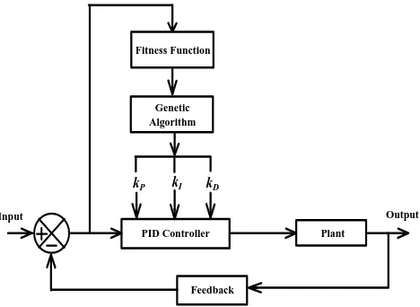
Proportional-Integral-Derivative (PID) control is one of the most widely employed methods in closed loop analysis of power converters. Hence, the technique has been employed here for observing closed loop optimized performance of SEPIC converter by utilizing Genetic Algorithm. The basic block diagram of the system is shown in Fig. 4. In order to tune the parameters of PID controller through genetic algorithm, the
kP, kI and kD are taken and the chromosome is formed. The main objective of the study is to minimize the error between the input and the plant’s output.
PID Controller Plant
Feedback Fitness Function
Genetic Algorithm
kP kI kD
Input Output
Fig. 4. Basic Block Diagram of GA Based PID Controller.
IV. SIMULATION RESULTS AND STABILITY ANALYSIS
With the help of the equations derived earlier, the state space model is turned into a higher order transfer function for the purpose of simulating the stability of the system [24]. Model order reduction technique is carried out in MATLAB so that the system can be converted into a simpler form. Table I presents the converter parameters that are used for
mathematical calculation and simulation of the stability of the SEPIC converter.
TABLE I.
PARAMETERS OF SEPICCONVERTER
Firstly, conventional PID controller is employed in SEPIC converter and the step response is taken to inspect the stability of the system which is shown in Fig. 5.
Fig. 5. Step Response of Conventional PID Controller
After that, Genetic Algorithm (GA) is deployed in the system to determine more optimum values of the PID controller. The parameters of the GA are selected by trial and error process in order to acquire the optimized values of kP, kI and kD. The parameters are listed in Table II.
TABLE II.
PARAMETERS OF GENETIC ALGORITHM
Population: 50
Fitness Scaling: Rank
Selection: Stochastic Uniform
Mutation: Constraint Dependent
Crossover: Constraint Dependent
Crossover Probability 0.8
After rigorous simulation in MATLAB, the values of kP, kI and
kD are obtained for all of the three performance indices of GA
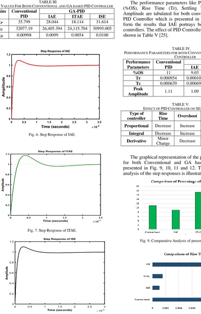
based PID controller which is evident in Table III along with the conventional PID controller. Step responses for IAE, ITAE and ISE are illustrated in Fig. 6, Fig. 7 and Fig. 8.
Parameter Symbol Values Input Voltage Vin 10 V
Switching
Frequency fs 100 KHz
Duty Cycle d 0.5
Inductor L1, L2 100 µH
Resistance
rL1, rL2 1 mΩ
rC1 3 mΩ
rC2 1 mΩ Capacitor C1,C2 800 µF, 3000 µF Load Resistance Ro 1 Ω
TABLE III.
GAIN VALUES FOR BOTH CONVENTIONAL AND GA BASED PIDCONTROLLER
Gains Conventional PID
GA-PID
IAE ITAE ISE
kP 35.799 28.044 18.114 31.614
kI 32077.19 26,405.394 24,115.704 30995.005
kD 0.00998 0.0099 0.0054 0.0100
Fig. 6. Step Response of IAE.
Fig. 7. Step Response of ITAE.
Fig. 8. Step Response of ISE.
The performance parameters like Percentage of Overshoot (%OS), Rise Time (Tr), Settling Time (Ts) and Peak Amplitude are tabulated for both conventional and GA based PID Controller which is presented in Table IV. It is evident form the results that IAE portrays better results than other controllers. The effect of PID Controller on SEPIC converter is shown in Table V [25].
TABLE IV.
PERFORMANCE PARAMETERS FOR BOTH CONVENTIONAL AND GA BASED PID CONTROLLER
Performance Parameters
Conventional PID
GA-PID
IAE ITAE ISE
%OS 11 9.03 17.2 10
Tr 0.000954 0.000102 0.000150 0.000985
Ts 0.000639 0.000694 0.00185 0.000676
Peak
Amplitude 1.11 1.09 1.17 1.11
TABLE V.
EFFECT OF PIDCONTROLLER ON SEPICCONVERTER
Type of controller
Rise
Time Overshoot
Settling Time
Steady State Error
Proportional Decrease Increase Small
Change Decrease
Integral Decrease Increase Increase Eliminate
Derivative Minor
Change Decrease Decrease No effect
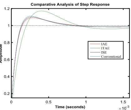
The graphical representation of the performance parameters for both Conventional and GA based PID Controller is presented in Fig. 9, 10, 11 and 12. The overall comparative analysis of the step responses is illustrated in Fig. 13
Fig. 9. Comparative Analysis of percentage of overshoot.
Fig. 11 Comparative Analysis of settling time (Ts).
Fig. 12 Comparative Analysis of peak amplitude.
Fig. 13 Comparative Analysis of Step Responses.
V. CONCLUSION
In this paper, an investigative study on stability analysis of closed loop SEPIC converter is brought into action. Genetic Algorithm is utilized to optimize the parameters of the PID controller. It is observed that IAE depicts more optimized results in terms of overshoot (9.03%), rise time (0.000102s), settling time (0.000694s) and peak amplitude (1.09) than other performance indices. The overall comparative analysis of step response provides an idea of the stability of the converter. Hence, GA based PID controller is more convenient than manually tuned conventional PID controller. So, more efficient and robust systems can be designed and analyzed by employing such optimization technique.
REFERENCES
[1] K. R. Kishore, B. F. Wang, K. N. Kumar, and P. L. So. "A new ZVS full-bridge DC-DC converter for battery charging with reduced losses over full-load range." In India Conference (INDICON), 2015 Annual IEEE, pp. 1-6. IEEE, 2015.
[2] K. Anoop and M. Nandakumar. "A novel maximum power point tracking method based on particle swarm optimization combined with one cycle control." 2018 International Conference on Power, Instrumentation, Control and Computing (PICC). IEEE, 2018.Sabyasachi, Sidharth and Pratyusha Mohanty. “Stability Analysis of Sepic Converter Using Matlab / Simulink.” (2014).
[3] C. Gobbato, S. V. Kohler, I. H. de Souza, G. W. Denardin, and J. de P. Lopes. "Integrated Topology of DC-DC Converter for LED Street Lighting System Based on Modular Drivers." IEEE Transactions on Industry Applications (2018).
[4] R. Chen, Z. Zhang, R. Ren, J. Niu, H. Gui, F. Wang, L. M. Tolbert, D. J. Costinett, and B. J. Blalock. "Common-mode noise reduction with impedance balancing in DC-fed motor drives." In Applied Power Electronics Conference and Exposition (APEC), 2018 IEEE, pp. 2515-2520. IEEE, 2018.
[5] C. Zhang, J. Wang, S. Li, B.Wu, and C. Qian. "Robust control for PWM-based DC–DC buck power converters with uncertainty via sampled-data output feedback." IEEE Transactions on Power Electronics 30, no. 1 (2015): 504-515.
[6] N. Ali, M. T. Hagh, M. B. B. Sharifian, and S. Danyali. "A nonisolated multiinput multioutput DC–DC boost converter for electric vehicle applications." IEEE Transactions On Power Electronics 30, no. 4 (2015): 1818-1835.
[7] K. S. Nathan, S. Ghosh, Y. P. Siwakoti, and T. Long. "A New DC-DC Converter for Photovoltaic Systems: Coupled-Inductors Combined Cuk-SEPIC Converter." IEEE Transactions on Energy Conversion (2018). [8] M. M. Nishat, F. Faisal, M. A. M. Oninda and M. A. Hoque. “Modeling,
Simulation and Performance Analysis of SEPIC Converter Using Hysteresis Current Control and PI Control Method.” 2nd Int. Conf. on Innovations in Science, Engineering and Technology (ICISET), IEEE 2018, in press
[9] M. B. Rashid, M. A. M. Oninda, F. Faisal, M. M. Nishat, G. Sarowar, and M. A. Hoque. "A Novel Topology of Single-Phase AC-DC Integrated Boost-SEPIC (IBS) Converter Using Common Part Sharing Method (CPSM) for High Step-Up Applications." Journal of Power and Energy Engineering 6, no. 06 (2018): 38.
[10] A. H. R. Rosa, T. M. de Souza, L. M. F. Morais, and S. I. Seleme. "Adaptive and nonlinear control techniques applied to sepic converter in dc-dc, pfc, ccm and dcm modes using hil simulation." Energies 11, no. 3 (2018): 602.
[11] S. S. Deshpande, and B. K. Chandrakant, "Design of multi scale PID controller for Temperature process." Automatic Control and Dynamic Optimization Techniques (ICACDOT), International Conference on. IEEE, 2016.
[12] K. S. Chia, "Ziegler-Nichols Based Proportional-Integral-Derivative Controller for a Line Tracking Robot." (2018).
[13] C. Singh, "Genetic Algorithms Based PID controller Design." International Journal of Enginering Development and Research 3.3 (2015): 2-5.
[14] G. Mantri, and N. R. Kulkarni. "Design and Optimization of PID Controller Using genetic algorithm." Int. J. Res. Eng. Technol 2.6 (2013): 926-930.
[15] E. E. Vladu, and T. L. Dragomir. "Controller tuning using genetic algorithms." International Journal of Research in Engineering and Technology (2004): 1-10.
[16] P. Shubham, K. Meenakshi, and G. Rajeev. "Optimal Tuning of PID Controller Using Genetic Algorithm and Swarm Techniques." International Journal of Electronic and Electrical Engineering (2014): 189-194.
[17] R. L. Jiménez, A. G. Aguilar, and V. L. G. De Velasco. "Close loop step test used for tuning PID controller by genetic algorithms." Pistas Educativas 36.112 (2018).
genetic algorithms in servo systems." International Journal of Advanced Robotic Systems 10, no. 9 (2013): 324.
[19] D. C. Meena, and A. Devanshu. "Genetic algorithm tuned PID controller for process control." 2017 International Conference on Inventive Systems and Control (ICISC). IEEE, 2017.
[20] G. Tian, W. Qi, Y. Yan, and Y. Z. Jiang. "High power factor LED power supply based on SEPIC converter." Electronics Letters 50.24 (2014): 1866-1868.
[21] J. Hammerbauer, and M. Stork. "State space study of the SEPIC converter." Applied Electronics (AE), 2013 International Conference on. IEEE, 2013.
[22] S. Durgadevi, and M. G. Umamaheswari. "Analysis and design of single-phase power factor corrector with genetic algorithm and adaptive neuro-fuzzy-based sliding mode controller using DC–DC SEPIC." Neural Computing and Applications (2018): 1-12.
[23] A. Mirzal, S. Yoshii, and M. Furukawa. "PID parameters optimization by using genetic algorithm." arXiv preprint arXiv:1204.0885 (2012). [24] S. Sabyasachi, and P. Mohanty. “Stability Analysis of Sepic Converter
Using Matlab / Simulink.” (2014).
![Fig. 1. Circuit Diagram of Conventional SEPIC Converter [20].](https://thumb-us.123doks.com/thumbv2/123dok_us/1349502.1643373/2.612.48.301.185.279/fig-circuit-diagram-conventional-sepic-converter.webp)
![Fig. 3. Flow Chart of Genetic Algorithm [19].](https://thumb-us.123doks.com/thumbv2/123dok_us/1349502.1643373/3.612.49.297.145.485/fig-flow-chart-genetic-algorithm.webp)