IMPLEMENTATION OF HOME AUTOMATION AND SECURITY
SYSTEM USING TOUCH SCREEN, REMOTE CONTROL AND
WEB BASED OPERATION
Dhiraj Sunehra1
1.INTRODUCTION
Now-a-days, home automation systems (HAS) are becoming popular for managing the devices and appliances at home. Many of home appliances can be conveniently controlled using a HAS. To support the disabled or elder people, wireless RF remote provides ease of operation. To achieve this, all the devices are integrated with mini PC. The remote controls are extensively used in wide range of applications because of the simplicity and ease of use. HAS are using some sensors to provide safety. Here, we present a Home Automation and Security System (HASS) where controlling can be done by either a RF remote control or a touch screen panel. In addition to controlling the loads, monitoring of temperature and humidity parameters are done using HAS. Several authors have presented HAS using speech recognition, Bluetooth, and GSM [1-3].
2.SYSTEMDESCRIPTION
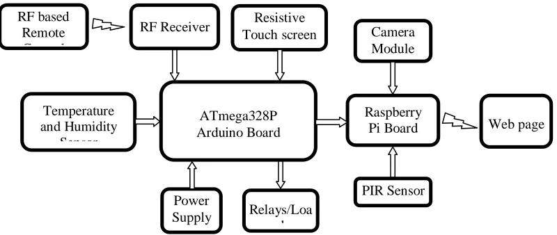
The block diagram of the HASS is shown in Fig.1. It includes temperature sensor, humidity sensor, RF receiver, a resistive touch screen and relays connected to the Arduino board. The Arduino is connected to the Raspberry Pi using an USB cable. The camera module and PIR sensor are connected to the Raspberry Pi. The loads connected to relays can be controlled by using either a RF remote control, resistive touch screen or through webpage. The image of the intruder captured by the webcam can be viewed on the webpage. The salient features of the various modules used are as follows.
Arduino Uno board consists of an AVR ATmega328P based microcontroller which is a 8-bit Reduced Instruction Set Computer (RISC). It has 14 digital I/O pins and 6 analog input pins. It has 2KB of SRAM. The Arduino board can be connected to a PC using a USB cable [4].
Raspberry Pi is a minicomputer designed by Raspberry Pi foundation. With 1 GB of RAM and 1.2 GHz frequency, it meets the standards of the present day smart phone. It has USB, HDMI and Ethernet ports. It also has Wi-Fi and Bluetooth modules [5]. A PIR sensor can detect the movement of warm bodies in its vicinity. It works on the principle of sensing heat. It can be used to detect human beings in the home within the range of about 10m. A resistive touch screen consists of two conducting layers placed one upon the other. When the user presses on the touch screen both the layers get in touch with the other and a voltage is generated based on potentiometer values which can be decoded to get the location on the touch screen.
1
Department of Electronics and Communication Engineering, Jawaharlal Nehru Technological University Hyderabad, Telangana 500085, India
DOI: http://dx.doi.org/10.21172/1.91.16
e-ISSN:2278-621X
Abstract- Modern homes are getting smarter with the advancements in engineering and technology. Conventional switches are being replaced with electronic touch screen switches and remote control based switch operation. Physical operation of wall switches placed in different corners of the house is not convenient especially for the elderly and physically disabled members present in the home. A Home Automation System (HAS) makes use of various sensors and components for controlling and monitoring the home environment. It helps in reducing human efforts and also saves energy. This paper presents the implementation details of a Home Automation and Security System (HASS) that uses a RF remote controller, temperature sensor, humidity sensor and touch screen to control electrical devices. The user can conveniently control the devices in the home by using this HASS. Touch screen control panels can be attractive compared to conventional switch boards. A camera is also interfaced for surveillance purpose. The image of the intruder is uploaded on to the Amazon web server. A webpage is developed using PHP and HTML for controlling the devices as well as to monitor the home environment when the user is away from home.
Fig. 1. Block diagram of Home Automation and Security System
The RF module operation can be clearly understood from Fig. 2. The RF transmission system uses amplitude shift keying (ASK) with the transmitter (Tx) and receiver (Rx) pair operating at 433 MHz. Switches are connected in parallel to the HT12E encoder, which encodes and converts it into serial data and sends it to the RF transmitter. The RF Rx. receives the serial data from RF Tx. It decodes the data and converts into parallel data. The parallel data is used by the microcontroller to control the loads connected to it using relays. The working of RF transmitter is depicted in Fig. 3.
Fig. 2. Working of RF Transmitter Receiver (Tx-Rx) module
3.SOFWARETOOLS
3.1 Arduino IDE
Arduino Integrated Development Environment (IDE) is an application used for writing and uploading the program code to Arduino Uno by connecting it to PC using a USB to serial cable. The code for interconnecting the sensors, RF Tx-Rx module and touch screen to the Arduino is written in Embedded C [6].
3.2 ExtraPuTTY
ExtraPuTTY is a remote computer login application. It is a free and open-source terminal emulator, serial console and network file transfer application. It can support various network protocols such as SSH, Telnet, etc. Before starting a session in PuTTY, we need to enter the IP address of Raspberry Pi. Later, we need to enter the username and password of the Pi to get the access to the Pi [7].
RF Transmitter 433 MHz
RF Receiver 433 MHz
Serial Data Serial Data
Encoder HT12E
Decoder HT12E
Parallel data Parallel data
Serial Data ATmega328P Arduino Board Temperature and Humidity Sensor Power Supply
RF Receiver Camera
Module Resistive
Touch screen
Raspberry
Pi Board Web page
Fig. 3. Working of RF Transmitter
3.3 PHP and HTML
PHP and HTML are used to the design the webpage. The GUI of the webpage can be designed using HTML. The server end scripting can be done with the help of PHP. It is used to generate the code corresponding to the button pressed, which is sent to Raspberry Pi [8-9].
4.SCHEMATICDIAGRAMANDFLOWCHART
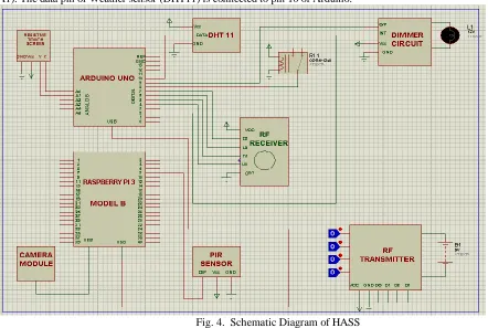
Figure 4 shows the schematic diagram of the HASS. The resistive touch screen is interfaced to the analog pins of Arduino (A0, A1). The data pin of Weather sensor (DHT11) is connected to pin 10 of Arduino.
Fig. 4. Schematic Diagram of HASS
The interrupt pin of dimmer circuit is connected to pin 2, and the output pin of it, to the pin 9 of Arduino. The 4 data pins of RF receiver are interfaced to four digital pins of Arduino, pin 4 to pin 7 respectively. A camera module is interfaced to USB port of
1
2
3
4
1
2
3
4
Switches
10
11
12
13
Encoder HT12E 4 Data Bits
+ 8 Address
Bits Serial Data
RF Transmitter 17
Raspberry Pi . The output pin of PIR sensor is connected to the GPIO pin 8 of Raspberry Pi. Finally, Arduino and Raspberry Pi are connected to each other using a serial communication cable. All the components are connected to 5V power supply and ground, with respective pins of microcontroller.
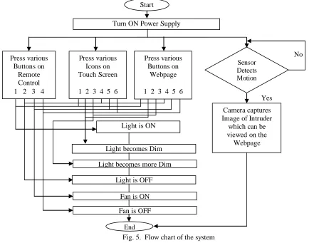
Figure 5 depicts the flowchart of the complete operation of HASS. The loads can be controlled in three ways: (i) using the RF remote control, (ii) Touch screen panel, and (iii) Webpage operated using any internet enabled device. When any human motion is detected by the PIR sensor, the camera uploads the image of the intruder. The light intensity of the bulb can be changed using appropriate buttons.
Fig. 5. Flow chart of the system
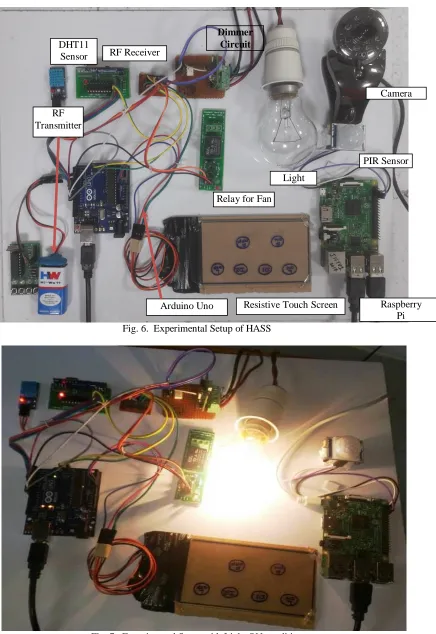
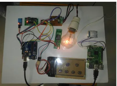
5.EXPERIMETALSETUPANDRESULTS
Figure 6 shows the experimental setup of the Home Automation and Security System. We can turn ON the light by pressing the appropriate button on the RF remote control or pressing the appropriate icon assigned on the touch screen panel or by clicking the Light ON button in the developed webpage. Figure 7 shows the snapshot of the HASS with light turned ON. We can control the intensity of the light using specially designed dimmer circuit. We have set two levels of intensity. To control the intensity of the bulb, there are two buttons named dimmer 1 and dimmer 2 on the touch screen and web control page. When dimmer 1 is pressed, the light intensity gets reduced. When dimmer 2 is pressed, the light intensity gets still lower. The snapshot for the two intensity levels of the light for dimmer 1 and dimmer 2 are given in Fig. 8 and Fig. 9.
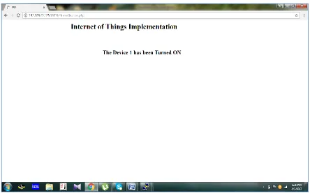
We can also control a fan connected to the relay (not shown in Fig.) using any of the control mechanism. The webpage can be viewed by entering the IP address in a browser, which displays the control buttons for fan and bulb as shown in Fig. 10. In this webpage, we can view the image of the intruder captured by the webcam in case of intrusion.
No Start
Turn ON Power Supply
Press various Buttons on
Remote Control 1 2 3 4
Press various Icons on Touch Screen
1 2 3 4 5 6
Press various Buttons on
Webpage
1 2 3 4 5 6
Sensor Detects Motion
Light is ON
Light becomes Dim
Light becomes more Dim
Camera captures Image of Intruder
which can be viewed on the Webpage
Fan is ON
Fan is OFF Light is OFF
End
Fig. 6. Experimental Setup of HASS
Fig. 7. Experimental Setup with Light ON condition
PIR Sensor RF
Transmitter DHT11
Sensor RF Receiver
Dimmer Circuit
Camera
Resistive Touch Screen Arduino Uno
Relay for Fan
Fig. 8. Experimental Setup with Light Dim condition
Fig. 10. Sample output on webpage showing image captured on webcam
By pressing each button, we get a feedback webpage showing the status of light/fan as shown in the Fig.11. The Humidity and Temperature values are displayed on the serial monitor as shown in Fig. 12.
Fig. 12. Humidity and Temperature values displayed on the Serial monitor
6.CONCLUSIONS
The use of Internet of Things (IoT) in home automation applications enables us to control various devices in the home remotely through any internet enabled device such as smartphone, and monitor the home environment in case of any intrusion. The proposed system has many advantages including safety, security, improved comfort, energy and cost savings. It is better from the scalability, flexibility and security point of view than other commercially available HAS.
7.REFERENCES
[1] Ch. Pandu Ranga Sai, V. Sameeka Datta, Sudheera, “Design of a Smart Remote”, International Conference on Circuit, Power and Computing
Technologies (ICCPCT), 18-19 March 2016, Nagercoil, India.
[2] Dhiraj Sunehra, Veena, M., “Implementation of Interactive Home Automation Systems based on Email and Bluetooth Technologies”, International
Conference on Information Processing (ICIP), Pune, 16-19 Dec. 2015.
[3] Van Der Werff, M., Gui, X., Xu, W.L., “A Mobile-Based Home Automation System”, 2nd International Conference on Mobile Technology, Applications
and Systems, Guangzhou, 15-17 Nov. 2005.
[4] Atmel, “8-bit AVR Microcontrollers ATmega 328/P Datasheet”.
[5] https://www.raspberrypi.org.
[6] Brian W. Evans, “Arduino Programming Note Book”, 2007.
[7] https://en.wikipedia.org/wiki/PuTTY
[8] Jon Duckett, “HTML & CSS Design and Build Websites”, Wiley, 2011.