© 2015 IJSRSET | Volume 1 | Issue 3 | Print ISSN : 2395-1990 | Online ISSN : 2394-4099 Themed Section: Engineering and Technology
Simulation & Analysis of A 3-Phase 4-Wire System for Evaluation &
Mitigation of PQ Problem using Unified Power Quality Conditioner
Gajendra Singh,
Harpreet Singh
Department of Electrical Engineering, Institute of Engineering & Technology, Alwar, Rajasthan, India.
ABSTRACT
Electric power is the most essential raw material impacting the bottom line of quality production economically on a commercial scale. It can‟t typically be stored like other commodities and is essentially required with continuous flow all the time. Electric power can be visualized as the epitome of „just in time‟ philosophy used like the components delivered to a production line by a trusted and approved supplier with no facility for „pre-inspection‟. Now a day due to increased use of power electronic device at the distribution level the efficiency and reliability of supply being supplied to consumers is deteriorating. The increased voltage sag, voltage swell, flicker and other power quality problem attract the attention of consumer toward quality of power being supplied to them. Increased PQ problems leads to increased power loss, malfunctioning of electrical equipment and large financial loss, therefore the issue need quick attention. In this paper an effort is made by author to resolve the voltage and current related issues with application of Unified Power Quality Conditioner in the preinstalled distribution networks where design change is not possible. The author used Direct Torque Controlled Induction Motor Drive as a nonlinear load and constant impedance RL load as linear one in a 3-phase, 4-wire distribution system and compared the results with and without use of UPQC.
Keywords: Power Quality, Voltage sag, Voltage swell, DTC induction motor drive, Interruption, UPQC
I.
INTRODUCTION
Electricity is the backbone of a country‟s economy and depict the quality of life of the people residing in it. Its quality and availability at reasonable cost is usually taken for granted, but the real life situation in majority of the cases is entirely different. The general mass of the people have to put up with poor quality and low reliability of electricity and make compromises for survival of the economy and quality of life in most of the developing countries.
The power appliances of the yesteryears had no dearth of materials or electricity and the power equipment could easily withstand dangerous voltage, current, or power transients without objection from any side. Those equipment consumed large amounts of electricity and yet performed well without hurting the consumer expectations. The machines in those days were
power quality problems. It is evident that a few seconds of outage or interruption is sufficient to bring our modern equipment to a screaming stop, resulting in hours of interrupted production which ultimately leads to loss in terms of capital. So if an industry is experiencing 8-15 temporary disturbances every year, costing billions of rupees in lost productivity. This is the reason, power quality related issues are so alarming for power researchers in present scenario.
This work deals with one of the many issues that is the power quality and the mitigation of the problems arising due to lack of it.
II.
METHODS AND MATERIAL
A. Power Quality
Power Quality means different things to different people. A very commonly understood definition of power quality is given below:
„Any power problem that results in failure or misoperation of customer equipment manifests itself as an economic burden to the user, or produces negative impacts on the environment.‟
The best practice to define it as the capability of an electrical appliance/system to operate efficiently and effectively without disturbing the performance or operation of any other equipment connected directly or in vicinity of it. Majority of electrical appliances and circuits are susceptible to misoperation or complete damage to the device when subjected to one or more power quality disturbances. The electrical appliance might be an electric machine, electronic gadget, PDA, printer, television, industrial equipment or any other household appliance. In last few years the issues related to power quality have gained enormous attention of power researchers because of the damage caused in terms production loss, waste of time, loss of economy etc. etc
B. Sources of Poor Power Quality
PQ problem is an integral issue of voltage, current and frequency concerned abnormalities in an electrical network. An ideal situation demands that, both the network's voltage and current waveform must be of sinusoidal shape. However, the presence of non-linear loads in the network
distorts the original shape of the waveforms. In general utility grid is responsible for any deterioration in the voltage quality of an electrical network while the customer‟s load influences the quality of current. Due to the interactions of these two quantities, the input supply becomes distorted that eventually leads to PQ disturbances in the network.
PQ defects can originate from equipment at consumer‟s end, or from the supply network. Typical origins of a defect are:
1) Sudden connection or disconnection of load 2) A power station suddenly going down 3) An overcharged line
4) A lightning strike
5) Harmonic distortions introduced by a generation unit or by a consumer load
6) Power electronic speed drives 7) SMPS
8) Miswired electrical network 9) Faults caused by birds and animals 10) Power electronic switching 11) Severe weather condition 12) Inadequate utility services
13) Improper circuit design of equipment
C. Need of Power Quality Protection
While power instabilities occur in an electrical system, the consumer end equipment and industrial productivity get affected to a great extent which indirectly adversely affects the economy of a nation. It is already said above that 8 – 12 momentary interruptions a day may cost billions of rupees in a year for a large scale business. For sensitive electronic devices, a momentary disturbance can cause important data corruption, interrupted business communications, proximity effect, irritation for labors working on machines, confusion between system components and equipment failure. A blackout, or power outage, is a complete loss of utility power, whether short- or long-term. Unplanned outages may occur as aging electrical grids and building circuits are overwhelmed by high demand. Blackouts are particularly dangerous at sites where safety or life support rely on power, such as hospitals, treatment centers and power plants.
Idle workforce and machinery
Customer dissatisfaction lead to order cancellation and transactions delay
Revenue and accounting problems such as bills and invoices are not prepared on time, payments slip held up leads to dissatisfaction among workforce etc.. etc..
Reduced efficiency of workforce
Businesses have huge investment in buildings, staff maintenance, production machineries etc., and power quality protection is a low-priced insurance policy against damages. If due to deviation in the supply production is stopped, major financial loss is occurred. Which ultimately leads to financial starvation for the consumers/businesses and provide hindrance in the overall growth of a nation.
D. Technology for Mitigation of Power Quality Problem
Previously passive filters were being used in power industry to mitigate the disturbances, because performance and quality was not the major concern at that time. But modern scenario is quite different because of increasing demand and modern electronic machinery usage attract the concern of consumers toward the quality of supply due to increased supply fluctuation, breakdown, voltage dips etc. Most newly developed mitigation devices use power electronics. These are commonly referred to as Flexible AC Transmission Systems (FACTS) Devices or Custom Power Devices when applied in the distribution. The FACTS technology opens up new prospects in the field of electrical engineering for controlling VAR and improving the usable available capacity of current as well as new upcoming advance systems. The custom power devices includes, Dynamic Voltage Restorer (DVR), Distribution Static Compensator (DSTATCOM), Unified Power Flow Conditioner (UPFC), Unified Power Quality Conditioner (UPQC)etc. etc..
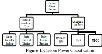
Mitigation of electrical disturbances can be done from either consumer end or utility end. The custom power devices are mainly divided into two groups:
1. Network reconfiguring type 2. compensating type
There are two general approaches to the mitigation of power quality problems First methodology used is load conditioning and the other is line conditioning. Load conditioning ensures the immunity of an equipment to withstand against electrical disturbances, allowing it to ride
through the disturbances. The other solution is to install line conditioning systems that suppress or counteracts the power system conflicts. However, with the restructuring of power sector, the line conditioning systems plays a vibrant role in enhancing the quality of supply being provided to the consumers.
Figure 1. Custom Power Classification
Network configuring type consist of
1) Solid State Current Limiter 2) Solid State Transfer Switch 3) Solid State Circuit Breaker
Compensating type can be categorized as
1) Dynamic Voltage Restorer 2) Distribution Static Compensator
3) Unified Power Quality Conditioner (UPQC)
E. Unified Power Quality Conditioner: State of Art
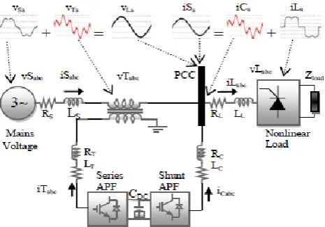
It is multi-functional devices that can be used to compensate voltage distortions and prevent harmonic abnormalities from entering into the system. UPQC constructional configuration consist of two voltage source converters sharing the same capacitive DC link. The DC-circuit allows the transfer of real power between shunt and series transformer to control the phase shift of the series voltage. One inverter, called the series inverter is connected via transformers between the source and the common connection point. The other inverter, called the shunt inverter is connected in parallel through the transformers. The series active power filter eliminates voltage flicker/imbalance and shunt filter absorbs the current harmonics contamination produced by the nonlinear loading
General Functions of UPQC
UPQC in general perform following operations when connected to a system:
1) Reactive power compensation 2) Provide better voltage Regulation
4) Compensation for current harmonics
5) Neutral current compensation for a 3-phase 4-wire systems
6) Power flow control
The general configuration of UPQC is shown below in figure 2 below
Figure 2. General Configuration of UPQC
F. Mathematical Modeling of UPQC
Figure 3. Equivalent Circuit of UPQC
Where
VS: Supply Voltage
VSR: Voltage at Series-APF,
VL: Load voltage
ISh: Current at Shunt-APF
Voltage distortion, make the system susceptible to negative sequence parameters and harmonic components.
The source voltage, in figure 3 can be represented by following equation:
S L SR V V V
In order to obtain sinusoidal shape of constant amplitude,
the output voltages of the series-APF must be given by:
1 1 2
(V V )Sin( t ) V (t) (t)
SR P Ln K K
V
VWhere,
1
V : Subscript “1” gives positive sequence of voltage
1p
: positive sequence phase angle of voltage
Ln V
: Negative sequence component of voltage
The output of shunt-APF contain harmonic, reactive and negative sequence components. For the compensation of such parameters in load current, the output current of shunt
APF ISh is kept equal to the load component as illustrated
by below equation:
1 1 1P 2
1 1 1
cos( t ) sin
L P P Ln K Lk
P P P
I I
I I
Where,
Subscript “1” represent the positive sequence of all the phase angles
From the above equations it can be seen that the load current is free from harmonic and is sinusoidal in nature having the same phase angle as the phase voltage at the load terminal, Therefore:
S L Sh I I I
1Psin( 1P) cos 1P
I
t
III. RESULTS AND DISCUSSION
G. Steady State Analysis
The UPQC is controlled in such a way that the voltage at the load bus is always sinusoidal and at desired magnitude. In the following analysis the load voltage is assumed to be in phase with terminal voltage even during voltage sag and swell condition. In this particular condition, the series active power filters (APF) could not handle reactive power and the load reactive power is supplied by shunt active power filters (APF) alone
Figure 4. Circuit Showing Source and Load Parameters
The source voltage, terminal voltage at PCC and load voltage are denoted by VS, Vt and VL respectively. The
respectively. The voltage injected by series APF is denoted by VSr, whereas the current injected by shunt APF is
denoted by iSh. Taking the load voltage VL, as a reference
phasor and suppose the lagging power factor of the load is cosφL then we can write,
VL VL 0
IL IL
LVt VL(1 k) 0
Where factor k represents the fluctuation of source voltage, defined as t L L V V K V
The voltage injected by series APF must be equal to
0
sr L t L V V V kV
The UPQC is assumed to be lossless and therefore, the active power demanded by the load is equal to the active power input at PCC. The UPQC provides a nearly unity power factor source current, therefore, for a given load condition the input active power at PCC can be expressed by the following equations,
t L P P
cos
t s L L L V i V i
(1 k) i cos
L s L L L
V V i
/ (1 k) *cos
s L L
i i
The above equation suggests that the source current iS
depends on the factor k, since ΦL and iL are load
characteristics and are constant for a particular type of load. The complex power absorbed by the series APF can be expressed as
*
cos cos
sin
sr sr s
Sr Sr s s L S S Sr Sr S S
S V i
P V i kV i
Q V i
S
= 0, since UPQC is maintaining unity power factor, Therefore the above equations become
*
0
sr sr s
Sr Sr s L S
Sr
S
V i
P
V i
kV i
Q
The complex power absorbed by the shunt APF can be expressed as,
*
sh L sh
S
V i
The current provided by the shunt APF, is the difference between the input source current and the load current,
which includes the load harmonics current and the reactive current. Therefore, we can write,
0
(cos
jsin
)
Sh S L
Sh S L L
Sh S L L L
i
i
i
i
i
i
i
i
i
cos (i i cos )
Q sin
Sh L Sh Sh L S L L Sh L Sh Sh
P V i V
V i
From above equations the control action of active and reactive power by UPQC can easily be calculated.
H. Test System Under Consideration
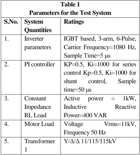
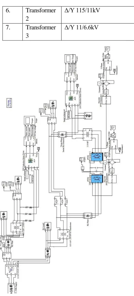
Simulation model of 3- phase, 4-wire distribution system having 11kV, 50Hz supply and containing constant impedance RL load and DTC induction motor drive as non- linear load with UPQC. For the generation of reference signals for both shunt and series active filters of UPQC, an approach based on two closed loop PI controllers for shunt and series active power filters (APFs) utilization, and other strategy unit vector template generation is implemented. The output from generating unit is fed to the primary of the three winding transformer. Further two parallel feeders of 11kV each are drawn. In one of the feeders UPQC is connected with a linear and nonlinear load and other feeder is kept as it is. The modeling and simulation of the system is done in MATLAB/SIMULINK software. The parameters of the test system are as listed in the table 1 below:
Table 1
Parameters for the Test System S.No. System
Quantities
Ratings
1. Inverter parameters
IGBT based, 3-arm, 6-Pulse, Carrier Frequency=1080 Hz, Sample Time=5 μs
2. PI controller KP=0.5, Ki=1000 for series control Kp=0.5, Ki=1000 for shunt control, Sample time=50 μs
3. Constant Impedance RL Load
Active power = 1kW, Inductive Reactive Power=400 VAR
4. Motor Load Voltage Vrms=11kV, Frequency 50 Hz
5. Transformer 1
6. Transformer 2
Δ/Y 115/11kV
7. Transformer 3
Δ/Y 11/6.6kV
Figure 5. Matlab Model of Distribution Network Carrying Linear and Nonlinear Load With and Without UPQC
I. Simulation Results when DTC Induction Motor Drive and Constant Impedance RL Load is Used
Here an ideal three-phase sinusoidal supply voltage is applied to a constant impedance RL load and a non-linear load (Direct Torque control Induction motor drive) injecting current and voltage harmonics into the system. The voltage and current waveform at each loading is carefully observed. The total harmonic distortion (THD) associated with current
and voltage waveform at linear and nonlinear loading is also observed.
Figure 6(a). Voltage Waveform Across Three Phase RL Load Without UPQC
Figure 6(b). Total Harmonic Distortion in Voltage Across Three Phase RL Load Without UPQC
Figure 6 (a) shows the voltage across three-phase constant impedance RL load before compensation without UPQC and figure 6 (b) shows THD level for uncompensated load voltage. The total harmonic distortion in the load voltage is found to be 3.04 %.
Figure 7 (a). Voltage Waveform across RL Load With UPQC
Figure 7(b). Total Harmonic Distortion in Voltage Waveform across RL Load With UPQC
Figure 8(a). Voltage Waveform across DTC Induction Motor Drive without UPQC
Figure 8(b). Total Harmonic Distortion in Voltage across DTC Induction Motor Drive Without UPQC
Figure 8 (a) shows the uncompensated voltage across DTC Induction motor drive load and figure 8 (b) shows THD level for uncompensated load voltage. The total harmonic distortion in the uncompensated voltages is found to be 14.59 %.
Figure 9(a). Voltage Waveform Across DTC induction Motor Drive With UPQC
Figure 9(b). Total Harmonic Distortion in Voltage Across DTC induction Motor Drive With UPQC
Figure 9 (a) shows the compensated voltage across DTC Induction motor drive load with the application of UPQC and figure 9 (b) shows THD level for the compensated load voltage. The total harmonic distortion in the uncompensated voltages is found to be 4.13 %. It shows that there is appreciable drop in THD level with the application of UPQC with nonlinear loading.
Figure 10(a). Current Waveform in Three Phase RL Load Without UPQC
Figure 10(b). Total Harmonic Distortion in Three Phase RL Load without UPQC
Figure 10 (a) shows the uncompensated current in constant impedance RL load, and figure 10 (b) shows the total harmonic distortion level in the load current. The total harmonic distortion in the uncompensated load current is found to be 2.50 %.
Figure 11 (a). Current Waveform in Three Phase RL Load With UPQC
Figure 11(b). Total Harmonic Distortion in Three Phase RL Load With UPQC
Figure 11(a) shows the compensated current in constant impedance RL load, and figure 11 (b) shows the total harmonic distortion level in the compensated current. The total harmonic distortion in the load current after compensation is found to be 2.31 %. This is a very small level of compensation or correction which shows that with linear loading the distortion in the current or voltages is not very large. Therefore it can be said that linear loading in not an issue to worry in a 3-phase, 4- wire distribution system
Figure 12(a). Current Waveform in DTC Induction Motor Drive Load Without UPQC
Figure 12(a) shows the uncompensated current in DTC Induction motor drive load, it is seen that current profile shown in the figure 12(a) is not perfect sinusoidal. Figure 12 (b) shows the total harmonic distortion level in the uncompensated current. The total harmonic distortion in the current without any compensation is found to be 27.30 %. This shows that distortion in the current with nonlinear loading is very large and require serious attention as it leads to deterioration in the performance of the load connected to it.
Figure 13(a). Current Waveform in DTC Induction Motor Drive With UPQC
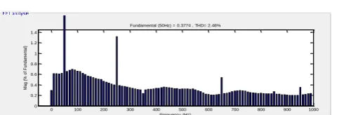
Figure 13(b). Total Harmonic Distortion in the current at DTC Induction Motor Drive With UPQC
Figure 13 (a) shows the compensated current in DTC Induction motor drive load, it is seen that current profile shown in the figure 13 (a) is near perfect sinusoid. Figure 13 (b) shows the total harmonic distortion level in the compensated current with the application of UPQC. The total harmonic distortion in the current without any compensation is found to be 2.46 %. This shows that distortion level in the current with the application of compensating device as UPQC has been resolved to a large extent. This suffice the purpose of the writing this thesis by selecting Unified power quality conditioner for PQ mitigation.
IV. CONCLUSION
Here a general review of what theoretical mitigation methods are available for the different types of power quality disturbances is presented. Mitigation on design level leads to high input capital and consume lot of effort and time therefore, the focus of the study lies on mitigation devices rather than mitigation through the design of the power system, production facilities and
loads connected to it. . Constant impedance RL load is used as linear load and direct torque controlled induction motor drive is used as non-linear one. It is found that distortion in voltages and currents with RL loading is very small and lies in acceptable limit, does not require much attention. But when it comes to nonlinear loading like DTC induction motor drive is the case the distortion in the voltage and current profile is quite appreciable, which cannot be ignored. When UPQC is used as compensating device, the substantial improvement in voltage and current profile as well as in THD level is observed.
Therefore, UPQC is considered to be an efficient solution for mitigation of power quality disturbances in non-linear loading. Unified power quality conditioner is capable of reducing the level of THD in the case of networks which are connected to the harmonics generating load (like ASD).
V.
REFERENCES
[1]. S. Sivanagaraju, “Electrical Power Transmission and Distribution”, Pearson Education, © Dorling Kindersley (India) Pvt. Ltd., ISBN: 978-81-317-0791-3, 2009. [2]. J.B.Dixit, Amit Yadav, “Electrical Power Quality”,
University Science Press, India, 2010.
[3]. N.G. Hingorani, "High Power Electronics and Flexible AC Transmission Systems," IEEE Power Engineering Review, Vol. 8, No. 7, July 1988, pp. 3-4
[4]. N. Mohan, T.M. Undeland, W.P. Robbins, “Power Electronics: Converters, Applications, and Design”, John Wiley & Sons, New York, 1989.
[5]. S. Banerjee, G.C. Verghese, “Nonlinear Phenomena in Power Electronics”, IEEE Press, New York, 2001. [6]. C. Shankaran, Power Quality, CRC Press LLC, New
York, 2002.
[7]. F. S. Gabrio “On compensation strategies for active filtering in power network” IEEE press, Milano, Italy. [8]. E. A. Mertens Jr., L. F. S. Dias, F. A. Fernandes,
“Evaluation and Trends of Power Quality Indices in Distribution System” 9th international conference on Electrical Power Quality and Utilization, Barcelona, , Page(s):1-6, 7-9 October 2007.
[9]. H. Siahkali,” Power Quality Indexes for Continue and Discrete Disturbances in a Distribution Area” 2nd IEEE International Conference on Power and Energy (PECon 08), December 1-3, 2008, Johor Baharu, Malaysia [10]. Y. Hyunjae, S.K. Seung “A New Circuit Design and
Control to Reduce Input Harmonic Current for a Three-phase AC Machine Drive System having a very Small DC-link Capacitor” IEEE Press, 978-1-4244-4783-1, 2010.
[11]. M. W. Sharad, A.V.Mohan “A STATCOM-Control Scheme for Grid Connected Wind Energy System for
0.1 0.15 0.2 0.25 0.3 0.35 0.4 0.45 0.5
-0.2 0 0.2
Selected signal: 25 cycles. FFT window (in red): 5 cycles
Time (s)
0 100 200 300 400 500 600 700 800 900 1000
0 0.2 0.4 0.6 0.8 1 1.2 1.4
Frequency (Hz) Fundamental (50Hz) = 0.3774 , THD= 2.46%
M
a
g
(
%
o
f
Fu
n
d
a
m
e
n
ta
Power Quality Improvement” IEEE Journal, VOL. 4, NO. 3, September 2010, ISBN1932-8184.
[12]. G.R. Sudharshan, K.K.Vijay “Unified Power Quality Conditioner (UPQC) During Voltage Sag and Swell” VSRD-IJEECE, Vol. 2 (8), 2012, 545-565, ISSN 2231-3346.
[13]. V.Khadkikar “Enhancing Electric Power Quality Using UPQC: A Comprehensive Overview” IEEE transaction on Power Electronics, Vol. 27, NO. 5, May 2012. [14]. K.W.Lao, N.Y.Dai, W.G.Liu, M.C.Wong “Hybrid
Power Quality Compensator With Minimum DC Operation Voltage Design for High-Speed Traction Power Systems”, IEEE Transaction on Power Electronics, Volume 28, No. 4, April 2013,PP 2025-2034
[15]. K. Srivani, A. Rajalaxmi “Review of UPQC Control Techniques for Power Quality Improvement”, International Journal of Scientific Research Engineering & Technology (IJSRET), ISSN 2278 – 0882, Volume 3, Issue 1, April 2014
[16]. P.Prasad, Md. Khaja Jainuddin, Y.Rambabu, V.K.R.Mohan Rao “Unified Power Quality Conditioner (UPQC) With Storage Device for Power Quality Problems” International Journal of Engineering And Science, Vol.3, Issue 8 (September 2013), PP 19-26, ISSN(e): 2278-4721, ISSN(p):2319-6483,
[17]. J. L. Afonso, H. J. Ribeiro da Silva, J. S. Martins “Active Filters for Power Quality Improvement” IEEE Porto Power Tech, 10-13 Set. 2001, Porto, Portugal, ISBN: 0-7803-7139-9
[18]. R.K. Rao, G.R. Kumar, S.S.Tulasiram “Harmonic Analysis of 6-pulse Converter in DTC Induction Drives using UPQC” International Journal of Scientific & Engineering Research Volume 2, Issue 10, October-2011, ISSN: 2229-5518.
[19]. M. Tarafdar Haque, and S.H. Hosseini, “A Control Strategy for Unified Power Quality Conditioner (UPQC) using Instantaneous Symmetrical Component Theory”, Conference on Proceedings of Power Electronics Specialists, Vol. 1, Page(s): 94 - 98, June 2002.
[20]. C. Benachaiba and B. Ferdi “Power Quality Improvement Using DVR”, American Journal of Applied Sciences 6 (3): 396-400, 2009, ISSN 1546-9239 [21]. R V D Rama Rao, Subhransu Sekhar Dash “Enhancement of Power Quality by using Unified Power Quality Conditioner with PID and Fuzzy Logic Controller” International Journal of Computer Applications (0975 – 8887) Volume 5– No.7, August 2010.
[22]. P. Kondala Rao and K. Vimala Kumar “Custom Power Improvement in Distribution Systemby Open UPQC” International Journal of Science and Research (IJSR), ISSN (Online): 2319-7064.
[23]. Mojtaba Nemati, Hesam Addin Yousefian and Rouhollah Afshari, “Recognize the Role of DVR in Power Systems”, International Journal of Recent Trends in Engineering, Vol. 2, Page(s): 13 - 15, November 2009. [24]. B. Singh, K. Al-Haddad and A. Chandra “A Review of
Active Filters for Power Quality Improvement” IEEE Transaction on Industrial Electronics, Vol. 46, No. 5, October 1999.
[25]. V. Khadkikar and A. Chandra “A New Control Philosophy for a Unified Power Quality Conditioner (UPQC) to Coordinate Load-Reactive Power Demand Between Shunt and Series Inverters”, IEEE Transaction on Power Quality Vol.3, NO. 4, October 2008.
[26]. B. Singh, S. Gairola, B.N.Singh, A.Chandra and K.Al-Haddad “Multipulse AC–DC Converters for Improving Power Quality: A Review”, IEEE Transaction on Power Quality, Vol. 23, No. 1, January 2008
[27]. B.B.Ambati and V. Khadkikar “Optimal Sizing of UPQC Considering VA Loading and Maximum Utilization of Power-Electronic Converters”, IEEE Transaction on Power delivery, Vol. 29, No. 3, June 2014.
[28]. S.Rajeev, “IUPQC Simulation for Power Quality Improvement”, International Journal of Engineering Research, Volume No.3, Issue No.40, ISSN:2319-6890)(online), 01 April 2014, pp : 261-264