Low Cost Two-Axis Automatic Solar Tracking System
Amevi Acakpovi
Department of Electrical and Electronic, Accra Polytechnic
P.O.Box: GP561 Accra, GHANA
Nana Yaw Asabere
Department of Computer Science, Accra Polytechnic
P.O.Box: GP561 Accra, GHANA
Daniel Babbo Sunny
Department of Electrical Eng., Accra Institute of Technology
P.O.Box: AN19782 Accra, GHANA
ABSTRACT
This paper presents the design and construction of a two-axis solar tracking system. The system is designed to track the movement of the sun in order to get maximum power from the solar panels as they follow the direction of the sun. Though existing tracking systems are available in the market, limited purchasing capabilities in developing countries has been the main drive behind the device presented in this paper. The system employs Light Dependent Resistors to sense the position of the sun which is directly communicated to a micro-processing board with ATmega328 microcontroller. The micro-processing board therefore commands a set of two stepper motor to re-orient the panel either horizontally or vertically in order to stay perpendicular to the sun rays. The design was constructed successfully and tested to determine the increase in efficiency. Evaluation results show that the new system performs 10.7% better than the static solar system. Moreover the implementation cost of $132.36 is lower than many other existing trackers with the same capabilities available in the market.
General Terms
Solar Tracking System, MPPT, Micro-processing
Keywords
Tracking, Microcontroller Programming, Light Dependent Resistors, Dual-axis tracking
1.
INTRODUCTION
Solar tracking systems have emerged over the time as one of the reliable techniques to increase the efficiency of solar systems. Tracking systems can be implemented with intelligent inverters as well as using mechanical systems to cater for the rotation of the solar field. Precisely, solar maximum power point tracking systems (MPPT) exist as electro-mechanical systems that sense the sun rays and move the whole panel to follow its direction in order to receive the highest possible sun ray at a given time in a day. There are several kinds of solar tracking systems that have been proposed in the literature. Yakup and Malik [1] and Bari [2] proposed various means of optimizing the tilt angle and orientation of solar collectors considering different geographical latitudes. Based on many literatures reviewed, including [3-7], solar tracking systems provide a minimum improvement of 5% over the static solar system.
Algifri and Al-Towai, [8] proved with some innovative algorithms that the performance of a solar cooker could be improved by 40% in Aden city (Yemen) for higher elevation angle and 70% for lower elevation angles. Moreover, it was shown in [9-10] that the amount of solar energy captured by a tilted collector could be increased by more than 40% by adjusting the tilt angle on a seasonal basis.
There are three broad methods of tracking: active, passive, and chronological tracking, [11]. In addition, solar trackers can be classified with respect to their rotational axis (degree of freedom) which can be static, single-axis or dual axis tracking systems. Chronological tracker is a timer-based tracking system whereby the structure is moved at a fixed rate throughout the day. The theory behind this is that the sun moves across the sky at a fixed rate. Thus the motor or actuator is programmed to continuously rotate at a “slow average rate of one revolution per day (15 degrees per hour)” [11]. This method of sun-tracking is very accurate. However, the continuous rotation of the motor or actuator means more power consumption and tracking the sun on a very cloudy day is unnecessary.
Passive tracking, unlike active tracking which determines the position of the sun in the sky, is based on the heating properties of a gas such as the one proposed in [11]. A passive tracker moves in response to an imbalance in pressure between two points at both ends of the tracker. The imbalance is caused by solar heat creating gas pressure that is driven to one side or the other which then moves the structure. This system has lower efficiency compared to other types of trackers, especially at low temperatures. Moreover, they have not yet been widely accepted by consumers [11].
In active tracking, the position of the sun in the sky during the day is continuously determined by feedback sensors such as photo-sensors, current, voltage sensors, and auxiliary cells [12, 18]. These sensors will trigger the motor or actuator to move the mounting system so that the solar panels will always be orthogonal to the sun throughout the day. The drawback for such a system is that it is very sensitive to atmospheric conditions like cloud shading and might not be able to continue tracking the sun in a cloudy day.
However, the driving element behind the selection of a tracking system is basically cost. Active tracking systems, even though popular, are very costly. To reduce the cost of effective solar tracking systems, this paper proposes a sensing unit made of light dependent resistors combined with a developed algorithm implemented in a microcontroller to handle the sun tracking.
The rest of the paper is organized as follow. Section two presents the materials and methods, section three presents the results and discussion and finally section four presents the conclusion.
2.
MATERIALS AND METHODS
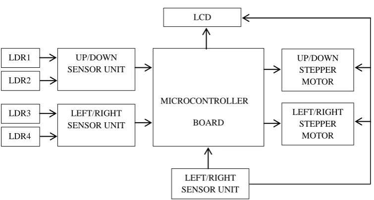
course of the day so as to achieve higher efficiency of power generation. The component of the electronic system consists of a microcontroller, a stepper motor, Light Dependent Resistors (photo sensors). The components are grouped into the following units and illustrated in the block diagram below.
Power supply unit
Light sensor unit
Stepper motor driver unit
Display unit
Central processing unit
2.1
Power Supply Unit
The ATmega328 requires a regulated 5 volt supply voltage. The IC LM7805 voltage was used with a 12 V voltage regulation circuit. The following calculations helped to determine whether the voltage regulator needed a heat sink. Input Voltage (Vin) = 12V
Output Voltage (Vout) = 5V
Current measurements from loads = 300mA Power dissipation by line regulator is given as
(1)
The calculated power that will be dissipated is small, therefore the voltage regulator will not need a heat sink.
2.2
Light Sensor Unit
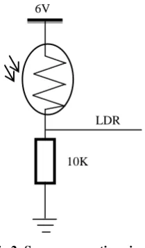
The light sensor is made up of Light Dependent Resistors, connected in series to a 10 KΩ resistor (R13) which forms a potential voltage divider network as illustrated in Figure 2. The midpoint of this network is then connected to the ADC pin of the microcontroller in the absence of light.
Fig 2: Sensor connecting circuit
The voltage going to the microcontroller can be calculated by the formula
(2)
2.3
Stepper Motor Unit
The solar tracker consists of two geared unipolar stepper motors along with their driver device. The output from microcontroller is sent to the motor driver which executes the proper sequence to turn the stepper motors in the required direction as shown in Figure 3.
To run the unipolar stepper motor in full drive or half drive mode, ULN20003A is used as motor driver IC. ULN2003A are high-voltage high-current Darlington transistor arrays. Each consists of seven NPN Darlington pairs that feature high-voltage outputs with common-cathode clamp diodes for switching inductive loads. The collector-current rating of a single Darlington pair is 500 mA. The Darlington pairs can be paralleled for higher current capability. The ULN2003A has a 2.7kΩ series based resistor for each Darlington pair for operating directly with TTL or 5V CMOS devices. Each coil of the stepper motor has two connections, the first one is connected to the 12 volts and the other one is connected to the IC output.
Fig 3: Stepper motor configuration circuits
2.4
Display Unit
The Liquid crystal display (LCD) is used to display information read from the level sensors. The LCD has an in-built controller which makes it easy to control it by an external microcontroller. Some features of the LCD screen are described below.
Fig 4: LCD screen configuration circuit
6V
LDR
a. Alphanumeric LCD (16 BY 2)
The LCD basically works on the concept of light polarization of liquid crystal under the influence of an electric field. The LCD contains a back light behind the liquid crystal array which acts as a light source. When an electric field is applied across certain fluids, it changes the way they allow light to pass through them thus it changes the orientation of the liquid crystal molecules as a result they do not allow light to pass through them. Hence by applying a suitable potential difference, we can control the LCD if light passes or doesn’t pass through the LCD pixels.
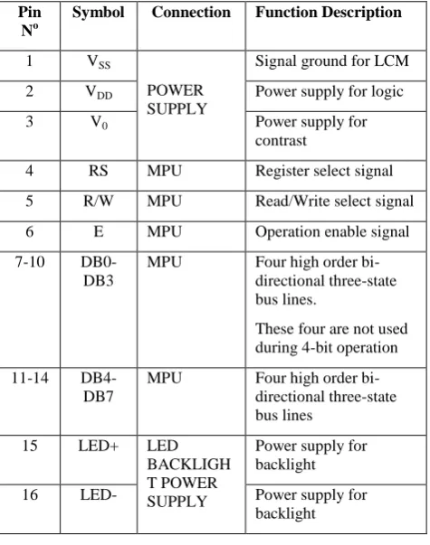
b. Pin-Out Configuration
Based on the LCD datasheet, pin 7 to 14 are the LCD 8 bit data bus which are connected to port B of the microcontroller ATmega328. The assignment of pin is shown in table 1.
Table 1: Pin-Out of the Microcontroller
Pin No
Symbol Connection Function Description
1 VSS
POWER SUPPLY
Signal ground for LCM
2 VDD Power supply for logic
3 V0 Power supply for
contrast
4 RS MPU Register select signal
5 R/W MPU Read/Write select signal
6 E MPU Operation enable signal
7-10
DB0-DB3
MPU Four high order
bi-directional three-state bus lines.
These four are not used during 4-bit operation
11-14
DB4-DB7
MPU Four high order
bi-directional three-state bus lines
15 LED+ LED
BACKLIGH T POWER SUPPLY
Power supply for backlight
16 LED- Power supply for
backlight
2.5
Central Control Unit
The main control unit is the ATMEL microcontroller ATmega328. All sensors are connected to the microcontroller unit which analyses their inputs and takes appropriate actions. Upon detection of a potential difference of voltage between the analogue voltages sensed by the LDRs, the following sequence is carried out by the controller.
The microcontroller analyses the difference
between the signals obtained from the LDRs
The microcontroller may send order to the stepper motor drivers to turn them on/off in order to orient the panel in the right direction of the sunlight.
The controller also displays a solar tracking message on the display unit.
The controller then stops the stepper motors (once there is no longer potential difference among the LDRs).
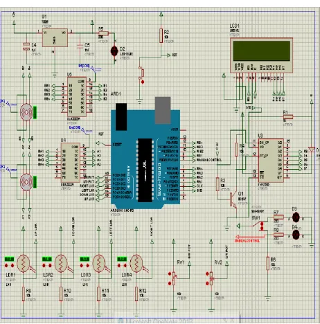
The overall circuit diagram is shown in Figure 5.
2.6
Assembly of the Solar Tracker
This section gives a step by step procedure of how all the individual parts were brought together and packaged. The housing used for the project is a 26 by 16.5 cm wooden box. Figure 8, 9, 10 and 11 show the assembled circuits
Measurement of the LCD were taken and used in cutting holes in front of the housing. This was done to enable visibility of the LCD screen.
Mounting holes were drilled for the main board and the system components were placed inside.
After fixing all the parts, they were connected to the appropriate points on the main board.
2.7
Program Development
This section depicts the process of developing the software. Flowcharts are used to show the processes of the main program and subsequent programs for the solar tracking and the LCD.
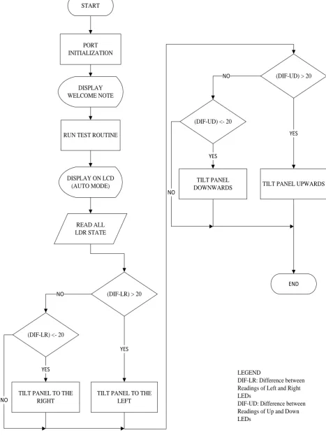
a. Flowchart of the main program
The flowchart in Figure 6 illustrates the logic and sequential flow behind the software program that run in the microcontroller used for the processing and control unit. When the system is first turned on, it displays a welcoming and performs a test run, where it test the system by moving the mounted solar panel on the tracking system up and down, left and right. After the system is settled whether to run in manual mode or automatic mode, it then reads the value of the light dependent resistors and finds out the potential difference between the two pairs of light dependent resistors, if the range for the pair of light dependent resistors is greater than the threshold of 20 and lesser than -20, the panel will shift left and right respectively and if the range for the other pair of light dependent resistors is greater than 20 and less than -20 the panel will shift up and down respectively. A threshold of 20 was experimentally chosen as a result of many tests and this value will not allow the stepper motor to be oversensitive.
b. Coding
C++ programming language was used in writing the code that runs in the flash memory of the microcontroller. The interactive development environment (IDE) within which the code was written, compiled and downloaded into the microcontroller is the Arduino IDE. Further simulations were equally run with the Proteus software.
3.
RESULTS
The results are discussed and interpreted in this section
3.1
System Testing
at the output terminal of each panel. Therefore, the output current and the output voltage were inferred using ohms law as follow
(3)
(4)
Table 2 shows the data of voltage, current and power received from the static solar panel and the solar tracking system for the duration of the experiment.
Table 2: Data collected from experimentation
HOURS From static solar panel From solar tracking panel Relative gaps
(V) (mA) (mW) (V) (mA) (mW)
06:00
AM 0.41 1.22 0.50 0.57 1.90 0.80 60
07:00
AM 3.05 10.16 31.00 3.07 10.23 31.41 1.32
08:00
AM 7.58 25.26 191.47 8.2 27.3 223.86 16.92
09:00
AM 8.12 27.0 219.6 8.68 28.93 251.11 14.35
10:00
AM 8.13 27.0 220.0 8.27 27.56 227.92 3.60
11:00
AM 7.90 26.3 208.0 8.00 26.67 213.36 2.58
12:00
PM 7.95 26.4 210.6 7.97 26.56 211.68 0.51
01:00
PM 8.03 26.7 214.9 8.05 26.83 215.98 0.50
02:00
PM 8.58 28.6 245.4 8.82 29.40 259.3 5.66
03:00
PM 8.18 27.2 223.0 8.32 27.73 230.71 3.46
04:00
PM 8.27 27.5 227.9 8.63 28.76 248.19 8.90
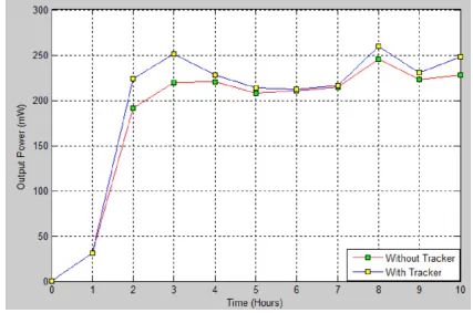
An illustration of the graphs of the power for the two systems i.e the system with tracker and the system without tracker is presented in Figure 7 below
Furthermore, the relative gaps between the two series of power obtained has been calculated based on the formula below
The average relative gap is
Where
PST is the power of the solar tracking system PS is the power of the static solar system
In addition, the solar tracker is constructed and illustrated in the appendix. Table 3 shows the implementation cost of the system.
Table 3: Cost of designed solar tracking systems
No. Item Quantity Unit Cost ($)
1 solar panel 1 24.90 24.90
2 Unipolar stepper
motor 2 23.59 23.59
3 12v battery 1 13.11 13.11
4 Acrylic Board 2 15.73 15.73
5 Shift Register 1 1.31 1.31
6 Stepper driver 1 2.62 2.62
7 Microcontroller
(ATmega328p) 1 9.17 9.17
8 LCD 1 10.48 10.48
9 Passive components 1 7.86 7.86
10
Bolt ,nuts, threaded rods & ball bearings
1 13.11 13.11
11 housing 1 6.55 6.55
12 PCB board 1 3.93 3.93
Total 132.36
4.
CONCLUSION
This paper presented a solar tracking system with an embedded microprocessor system. The sensing of the sun’s position was achieved by the use of four LDRs placed strategically to detect the position of the sun that could be up, down, left or right. Based on the detected position by the four LEDs, the panel is titled in the direction of the sun as to form a perpendicular angle with the sun ray in order to absorb the maximum radiation available at a time. The system was constructed and operated successfully. It was further tested against a static solar system for the purpose of determining the level of improvement. Results show an average increase in power production of about 10.7%. This finding corroborates the assertion that a solar tracking system provides a minimum improvement of 5% over the static solar system. Additionally, the cost of implementation of the system was $132.36 which is comparatively lower.
5.
ACKNOWLEDGMENTS
We appreciate the effort of the following experts who have contributed towards the development of this solar tracking system.
o Whiston T. M. Vanderpuye
o Justice Neequaye
6.
REFERENCES
[1] H.M. Yakup, A.Q. Malik, “Optimum tilt angle and orientation for solar collector in Brunei Darussalam”, Elsevier Journal of Renewable Energy, 2001, Vol. 24, pp. 223–234.
Elsevier Journal of Energy Conversion and Management, 2000, Vol. 41, pp. 855–860.
[3] Charles, R.L. 2002. Optimum orientation of solar panels. Retrieved from http://www.macslab.com/optsolar.html [4] C. Chin, A. Babu, and W. McBride, "Design, modeling
and testing of a standalone single axis solar tracker using MATLAB/Simulink", Elsevier Journal of Renewable Energy, 2011, Vol. 36, pp. 3075-3090.
[5] Khlaichom, P. and Sonthipermpoon K. 2006.
Optimization of solar tracking system based on genetic algorithms. Retrieved http://www.thaiscience.info/.
[6] O. Bingol, A. ALTINTAS, and Y. O¨NER,
"Microcontroller based solar-tracking system and its implementation", Journal of Engineering Sciences, 2006, Vol. 12, No. 2, pp. 243-248.
[7] R.H. McFee, “Power collection reduction by mirror surface non-flatness and tracking error for a central receiver solar power system”, Applied Optics, 1975, Vol. 14, pp. 1493-1502.
[8] A.H. Algifri and H.A. Al-Towaie, “Efficient orientation impacts of box-type solar cooker on the cooker performance”, Elsevier Journal of Solar Energy, 2001, Vol. 70, pp. 165–170.
[9] A. Bairi, “Method of quick determination of the angle of slope and the orientation of solar collectors without a sun tracking system”, Solar Wind Technology, 1990, Vol. 7, pp. 327–330.
[10] C.Y. Lee, P.C. Chou, C.M. Chiang and C.F. Lin “Sun Tracking Systems: A Review”, Sensors, 2009, Vol. 05, pp. 3875-3890; DOI:10.3390/s90503875.
[11] M. Clifford and D. Eastwood, "Design of a novel passive solar tracker", Elsevier Journal of Solar Energy, 2004, Vol. 77, pp. 269–80.
[12] S.A. Kalogirou, “Design and construction of a one-axis sun-tracking system”, Elsevier Journal of Solar Energy, 1996, Vol. 57, pp. 465-469.
[13] A.N. Khalifa, S.S. Al-Mutawalli, “Effect of two-axis sun tracking on the performance of compound parabolic concentrators”, Elsevier Journal of Energy Conversion and Management, 1998, Vol. 39, pp. 1073-1079. [14] P. Roth, A. Georgieg, H. Boudinov, “Design and
construction of a system for sun-tracking”, Elsevier Journal of Renewable Energy, 2004, Vol. 29, pp. 393-402.
[15] A. Al-Mohamad, “Efficiency improvements of photo-voltaic panels using a sun tracking system”, Applied Energy, 2004, Vol. 79, pp.345–354.
[16] M. Alata, M.A. Al-Nimr, Y. Qaroush, “Developing a multipurpose sun tracking system using fuzzy control”. Elsevier Journal of Energy Conversion and Management, 2005, Vol. 46, pp. 1229-1245.
[17] G.C. Bakos, “Design and construction of a two-axis sun tracking system for parabolic trough collector (PTC) efficiency improvement”, Elsevier Journal of Renewable Energy, 2006, Vol. 31, pp.2411–2421
[18] Semma, R.P. and Imamura, M.S. 1980. Sun tracking controller for multi-kW photovoltaic concentrator system. In Proceedings of the 3rd International Photovoltaic Solar Energy Conference, Cannes, France.
7.
APPENDIX
Fig 1: System’s block diagram
LDR1
LDR2
UP/DOWN SENSOR UNIT
LDR3
LDR4
LEFT/RIGHT SENSOR UNIT
MICROCONTROLLER
BOARD
UP/DOWN STEPPER
MOTOR
LEFT/RIGHT STEPPER
MOTOR
LEFT/RIGHT SENSOR UNIT
START
PORT INITIALIZATION
RUN TEST ROUTINE DISPLAY WELCOME NOTE
DISPLAY ON LCD (AUTO MODE)
READ ALL LDR STATE
(DIF-LR) > 20
(DIF-LR) <- 20
TILT PANEL TO THE RIGHT
TILT PANEL TO THE LEFT
(DIF-UD) > 20
(DIF-UD) <- 20
TILT PANEL
DOWNWARDS TILT PANEL UPWARDS
END NO
YES
YES
NO
YES
YES
NO
NO
LEGEND
DIF-LR: Difference between Readings of Left and Right LEDs
DIF-UD: Difference between Readings of Up and Down LEDs
Fig 7: Output power from static panel and solar tracker for various durations
Fig 8: Construction phase I Fig 9: PCB Design illustration II