Journal of Engineering Sciences, Volume 6, Issue 1 (2019), pp. E 25–F 32 E 25 JOURNAL OF ENGINEERING SCIENCES
ЖУРНАЛ ІНЖЕНЕРНИХ НАУК
ЖУРНАЛ ИНЖЕНЕРНЫХ НАУК
Web site: http://jes.sumdu.edu.ua
DOI: 10.21272/jes.2019.6(1).e5 Volume 6, Issue 1 (2019)
UDC621.671:621.668:532.528
Influence of an Inlet Rotating Axial Device on the Cavitation Processes
in a Low Specific Speed Centrifugal Pump
Moloshnyi O. M.1*, Szulc P.2, Sotnyk M. I.1
1
Sumy State University, 2 Rymskogo-Korsakova St., 40007 Sumy, Ukraine; 2
Wroclaw University of Science and Technology, 27 Wybrzeze Wyspianskiego St., 50-370 Wroclaw, Poland
Article info: Paper received:
The final version of the paper received: Paper accepted online:
December 1, 2018 March 21, 2019 March 26, 2019
*
Corresponding Author’s Address:
[email protected]
Abstract. The paper is devoted to the analysis of the cavitation processes in the flow section of the low specific speed centrifugal pump. A new conception of double-entry hermetic pump leads to the application of special shaped inlet device, which is a part of an electrical motor rotating element. Four flow geometrical models of the axial inlet device were taken into consideration. The first model, treated as referential and basic, has a cylindrical shape with small diffuser and a cone in front on the impeller. Other three models consist of the motionless cone, which was part of the housing, straight pipe, and diffuser section rotating analogously to the impeller and a spherical fairing. The re-search was conducted using physical experiments and numerical simulations of the workflow in the ANSYS CFX software environment. The analysis of the results shows that the pump with the basic model of the inlet device has NPSH 3 % above the average values. The comparison between CFD and experiment of the cavitation curves shape showed its similarity but determined by means of the physical experiment have higher values. Cavitation in the im-peller starts earlier than in the axial inlet device. The zones of the cavitation in the axial inlet device are located after the cone, at the beginning of the diffuser section and near the fairing at the outlet of the diffuser section.The cavita-tion zone, which is located after the cone, is separated from the walls of the axial inlet device. The value of the NPSH 3 % increases, when the diameter of the axial inlet device decreases, as the result of the raise of head loses in the inlet structure.
Keywords: inlet chamber, inlet nozzle, intake section, suction casing, cone, diffuser, CFD, NPSH, cavitation performance.
1
Introduction
Cavitation is a negative phenomenon that can occur in a pump. Its appearance in the preliminary phase leads to the increasing of the pulsation of a pressure, as well as the raise of the vibration and noise. Further development of the cavitation reduces the head and the efficiency of the pump. A consequence of the long cavitation process, the destruction of the impeller material could be ob-served. Therefore, scientists and engineers are devoting a lot of attention to the study and understanding of the cavi-tation phenomenon and ways to reduce the likelihood of its occurrence in rotating machinery.
As it is known, the greatest influence on the appear-ance of cavitation has the pressure at the impeller inlet and the temperature of the water. Moreover, the structure of the flow at the impeller inlet has also significant im-pact on the cavitation performances of the pump. It is
determined by the shape and geometrical parameters of the inlet device, the inlet part of the impeller, the leading edges of the blades, the design of an inducer (if it is) and, of course, of the rotating speed.
2
Literature Review
The most popular method for eliminating cavitation in the impeller is the addition of the inducer [1]. However, in this case, cavitation may occur on the inducer blades. To weaken the cavitation processes Jiang et. al [2] pro-posed additional flow jets in front of the inducer. Tkach [3] demonstrated the benefits of using a stator sleeve with ribs around the inducer to reduce the cavitation erosion.
E 26 MECHANICAL ENGINEERING: Computational Mechanics cavitation performances of the pump deteriorated with the
increase of the flow rate.
Tan et. al [5, 6] discovered, that the cavitation perfor-mances deteriorate when the pump is regulated by prewhirl of the flow by inlet guide vanes in front of the impeller. At the same time, there was a slight increase in pressure and efficiency. Skerlavaj et. al [7] discovered a decrease in the cavitation area on the suction side of the blades when the fluid is swirled in the symmetric inlet casing. However, Nagahara et. al [8] discovered that a large swirling of the flow in the inlet device of the verti-cal pump led to the formation of a cavitation vortex.
According to the results of the experiment conducted by Sikora et. al [9] the process of the appearance of the cavitation bubbles in a direct inlet pipe was accompanied by a decrease in volume flow. Cucha et. al [10] presented a comparison of the results of a numerical and an experi-mental study of cavitation in the nozzle. The cavitation zone occurs immediately after a sudden entry into the nozzle and is stretched under the walls.
Hergt et. al [11] found that the diffuser before the im-peller reduces the length of the recirculation zone and reduces the risk of the cavitation. In turn, Gulich [12] noted the efficiency of using the diaphragm to reduce the cavitation. Limbach [13] analyzed the pump with the diffuser but did not describe its effect on the cavitation phenomena and performances. Moloshnyi et. al [14] ana-lyzed the cavitation processes in a pump with the similar shape of inlet device and found the cavitation zone in the diffuser. Using the sudden expansion at the outlet of the diffuser decreases their area.
The literature review shows that the influence of the change in the cross-sectional area of the inlet device and the rotation of its walls on cavitation processes in the pump are not sufficiently described.
To determine the influence of the diameter of the pas-sage channel in the axial inlet device (AID) with rotating walls on the cavitation performances of the pump and the structure of the cavitation zones in the AID and impeller.
3
Research Methodology
3.1
Object of a study
The object of the study is a low specific speed close coupled centrifugal pump, which corresponds to half of double entry pump. Nominal flow rate Qnom = 16 m3/h, head H =10 m, rotational speed n = 1450 rpm, specific speed nq = n·Q0.5/H0.75≈17.5 rpm. Impeller eye diameter D0 = 63 mm, impeller outer diameter D2 = 192 mm, the number of impeller blades z = 7.
Four structures of the AID were dedicated for consid-eration and research. The construction of AID 0 was a cylindrical shape with a slight diffuser and a cone in front of the impeller (Fig. 1). The AIDs 1,2,3 were designed as an inlet device of the double entry pump. The fluid flows into the cavity of the pump shaft, which additionally is a part of the inlet device. The AIDs 1, 2, and 3 have a mo-tionless cone at the inlet which is part of the housing,
straight and diffuser sections, which are rotating with the rotational speed of the pump shaft, and also a spherical fairing. The diameter of the cylindrical section (d) for AIDs 1, 2, 3 was respectively 44 mm, 40 mm, and 36 mm. The diameter of the inlet pipe (Din) was 65 mm. The total length of all AID (L) was 260 mm and the rotat-ing AIDs section length (lrot) was 207 mm. The length of the cone (lcon) and the diffuser section of the AIDs (ldif) was 33 mm and 51 mm, respectively. The inner diameter of the outlet from the AIDs (dout) was 20 mm. Overall dimensions of analyzed AIDs were limited by the dimen-sions of the pump housing. The maximum diffuser angle (ϑ) for organizing the uniform flow out of the diffuser was calculated by the formula given in [12]:
ϑ = 16,5[d/(2ldif)]0.5 =16.5·[44/(2·51)]0.5 = 10.8°.
Diffuser angle of the AID 1 was assumed as 10.5°, which is permissible, but for other investigated AIDs, it exceeded this value.
Figure 1 – Scheme of the AID models
3.2
Physical experiment
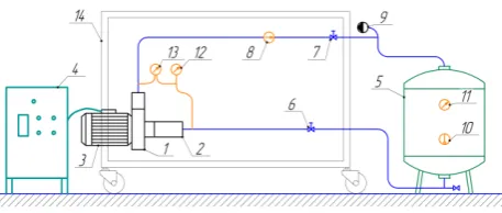
The physical experiment, to determine the cavitation performances of the pump with different AID structures, was conducted on a special prepared test rig (Fig. 2).
Figure 2 – Principal scheme of the experimental stand: 1 – researched pump; 2 – housing of the AID; 3 – electric motor; 4 – frequency converter with integrated powermeter;
5 – tank; 6, 7 – valves; 8 – electromagnetic flowmeter; 9 – vacuum pump; 10 – thermometer; 11 – pressure gauge; 12 – electronic pressure-and-vacuum gauge; 13 – electronic differential pressure gauge; 14 – mounting frame of the stand
Hydrau-Journal of Engineering Sciences, Volume 6, Issue 1 (2019), pp. E 25–F 32 E 27 lic performance acceptance tests. Accuracy classes of
applied measuring devices were: the electronic pressure and vacuum gauge and electronic differential pressure gauge – 0.5, powermeter – 0.5 and electromagnetic flowmeter – 0.5. The pumping fluid during the test was pure water at temperature 25 °С. The physical experiment was carried out for the AIDs 0, 1, and 2. During the test, the decrease of the pressure at the inlet was made by means of the vacuum pump.
3.3
Numerical simulation
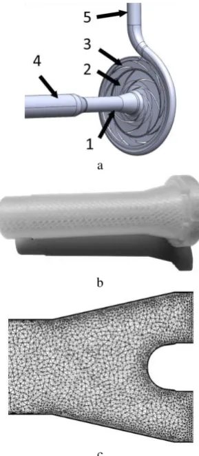
The model of a fluid computational domain of the re-searched pump was constructed at the beginning (Fig. 3 a). It contains the suction and discharge pipes, the AID, the impeller and the spiral with guide vanes. Sim-plification of the flow domain was made by assuming that there are no sinuses in the pump, to reduce the com-plexity of the grid and increase the speed of the calcula-tion. According to comparative calculations, such as-sumptions influenced no the results of the final calcula-tion within 1 %. Numerical simulacalcula-tion of the flow were carried out for 4 models of the AID.
a
b
c
Figure 3 – Investigated model: a – solid model of flow parts of the pump: 1 – axial inlet device (AID); 2 – impeller; 3 – the spiral with guide vanes; 4 – suction pipe; 5 – discharge
pipe; b – the plastic rotating part of the AID 2; c – the mesh of the diffuser section with fairing of the AID 2
The numerical simulation of fluid flow in the compo-nents of the pump was conducted using the ANSYS CFX software. The Rayleigh–Plesset equation, the standard k– ε turbulence model and the Reynolds equation was used. Boundary conditions were: the total pressure at the pump inlet and the mass flow rate at the pump outlet. Working fluids were water and water–vapor at temperature 25 °C. The saturated steam pressure was set as 3167 Pa. The surface roughness of the printed elements was assumes as 25 μm. The numerical calculation was carried out at (0.7, 1.0, 1.3)·Qnom.
An unstructured mesh was generated using software ICEM–CFD (Fig. 3 c). Elements size was selected via mesh independence research. Layers of prismatic ele-ments were created near solid walls in the boundary lay-er. The total number of nodes of the pump model was 3.3 mln. The inlet device, the impeller and the spiral con-tain 0.5 mln, 1 mln and 1.25 mln nodes, respectively.
4
Results and Discussion
The cavitation performances of the pump for (0.7, 1.0, 1.3)·Qnom are determined (Fig. 4). The value of the Net Positive Suction Head (NPSH) is determined by the drop of the head value by 3 % (NPSH 3 %). The basic AID has the lowest cavitation performances. According to the results of the numerical experiment NPSH 3 % is 0.3 m at Qnom. The maximum NPSH3% was achieved for the AID 3 – 1.2 m at Qnom. The value of the NPSH 3 % in-creases, when the diameter of the AID decreases. This is caused by an increase of the losses in the AID and the change in the structure of flow at the impeller eye.
A sharp drop of the pump head in course of the raise of the intensification of the cavitation phenomena is charac-teristic of the pumps with a low value of the specific speed. The smallest area of the passage channel relative to other places of the impeller is located between leading edges of neighboring blades. In the process of the devel-oping cavitation, the vapor quickly occupies the passage between blades and leads to a breakdown of the working process of the pump. The increase of the flow rate leads to the raise of NPSH 3 %, which is typical for the low specific speed pumps.
nor-E 28 MECHANICAL ENGINEERING: Computational Mechanics mal in case of non–symmetrical clearance in the seals.
That is why the results can be considered as accepted. An important criterion for evaluating the occurrence of cavitation in the pumps with geometrically non-similar inlet device is the suction specific speed nss. It is defined as [12]:
,
4 / 3 3 NPSH
f Q n
nss nom q
where fq is the number of the impeller eyes per impel-ler.
a
b
Figure 4 – Comparison of the cavitation performances curves: a – head–drop curves at Qnom; b – NPSH 3 % curves
at (0.7; 1.0; 1.3)· Qnom
The calculated value of the suction specific speed at Qnom for AIDs 0,1,2,3 is respectively 231, 160, 118, and 85. Typical values for centrifugal pumps with a standard impeller and an axial or semi–spiral inlet device are in the range of 160–220 [12]. That is, the AID 0 has better per-formance than standard pumps, AID 1 has a permissible value and AIDs 2, 3 have understated. However, it should be noted that the baseline for comparison is taken for pumps with a higher specific speed than the considered pump.
The AID 2 has a good head, energy, cavitation per-formances and also has the most optimal dimensions in terms of design features. More could be found in [15]. For further analysis, the AID 2 was adopted.
The first occurrence of the cavitation was observed in the impeller at the suction side of the blades (near the
leading edge) (Fig. 5 a). It is caused due to the flowing around the blades and the deviation of the direction of the flow. That means, the blade angle is too large and real Qnom at bigger value is approximately 17 m
3
/h. This is confirmed by Limbach [13]. These zones are larger in the AID 0 than in the AID 2 for NPSH = 3.76 m at Qnom. However, their size does not affect the change in the pump head.
a
b
c
Figure 5 – The cavitation structure in the impeller at Qnom: a – AID2 NPSH = 1.71 m; b – AID 0 NPSH 3 % = 0.31 m;
Journal of Engineering Sciences, Volume 6, Issue 1 (2019), pp. E 25–F 32 E 29 The size of the cavitation zones and the content of
wa-ter vapor increase, with the decreasing of the NPSH val-ue.There is the uniform “growth” of the cavitation zone on the blades surface for the AID 0 (Fig. 5 b). There is a significant zone of the cavitation on the suction side of the blades, which occupies and overlaps about 2/3 area of the passage between leading edges of neighboring blades at the NPSH 3 % for the AID 0.
a
b
c
d
Figure 6 – The vapour volume fraction distribution in the impel-ler cross section at a distance of 3/4 width of the blade from the
front shroud at the leading edges at Qnom:
a – AID 0 NPSH 3 % = 0.31 m; b – AID 1 NPSH 3 % = 0.51 m; c – AID 2 NPSH 3 % = 0.77 m; d – AID 3 NPSH 3 % = 1.19 m
a
b
c
Figure 7 – The pressure distribution in the impeller cross section at a distance of 3/4 width of the blade from the front shroud at the leading edges at Qnom for the AID 2: a – 0.7·Qnom
NPSH 3 % = 0.38 m; b – QnomNPSH 3 % = 0.77 m; c – 1.3·QnomNPSH 3 % = 1.31 m
In the cases, for AIDs 1, 2, 3, there are larger cavita-tion zones in the impeller eye at the NPSH 3 % than in the AID 0, which differs significantly in shape. They are located near the suction side of the blades and close to the front shroud (Fig. 5 c). Mentioned zones overlap 1/2 area of the passage between leading edges of neighboring blades. This was caused by the union of the cavitation zone of the diffuser with the cavitation zone in the impel-ler and the change in the direction of the absolute velocity at the impeller inlet. The reduction of the diameter of the AID causes the displacement of the cavitation zone in the impeller to the front shroud.
The vapour distribution in the impeller cross section at a distance of 3/4 width of the blade from the front shroud at the leading edges demonstrates a decrease in the cavi-tation zone (Fig. 6), but really the cavicavi-tation zone just shifts to the front shroud. This confirms the above pre-sented conclusions regarding the change in the cavitation zone (Fig. 5 b, c).
The distribution of the absolute pressure in the impel-ler at (0.7, 1.0, 1.3)·Qnom is qualitatively similar (Fig. 7). However, larger areas of low pressure at the suction side of the blades near the leading edges are observed for a smaller value of the flow rate. This causes an increase in cavitation zones.
a
b
c
d
Figure 8 – The vapour volume fraction distribution in a longitu-dinal section of the AID at Qnom:
E 30 MECHANICAL ENGINEERING: Computational Mechanics Cavitation in the AID 0 does not occur under the
con-sidered conditions (Fig. 8). There is an increase in the area of the cavitation zones in the diffuser section of the AID, when the diameter is reduced and the diffuser angle is simultaneously increased, which is a consequence of the strengthening of the detachment process. It should be noted, that cavitation in the impeller begins earlier than in the AID. At the same time, the value of the required NPSH (NPSHR = 1.3·NPSH 3 %) coincides with the first occurrence of cavitation in the AID and rather large cavi-tation zones in the impeller. That is, first of all, the de-struction of the material through cavitation will be in the impeller. It should be noted, that there are significantly smaller zones of cavitation in the diffuser of the AID 3 compared AIDs 0, 1, 2, but there is an essential decrease in pressure.
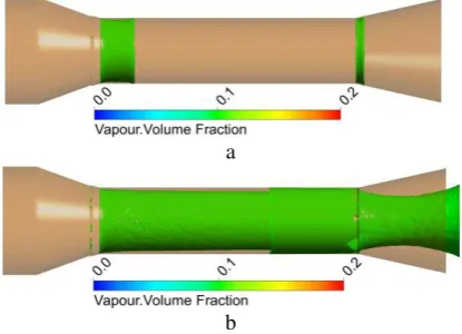
Places of appears and structure of the cavitation zones are illustrated by the example of the AID 2 (Fig. 9). Cavi-tation almost simultaneously appears in two zones (Fig. 9 a). The first zone is after cone at the beginning of the straight section. The second zone is at the beginning of the diffuser section of the AID. The cavitation zones are similar in the AIDs 1, 2, and 3. These zones are rapid-ly increasing by area with decreasing NPSH value (Fig. 9 b). In addition, cavitation appears in the third zone, located near the fairing at the outlet of the diffuser section. The cavitation zone increases and overlaps big-ger area at the impeller eye, which leads to the decrease of the flow diameter of the AID.
a
b
Figure 9 – The cavitation structure in the AID 2 at Qnom: a – NPSH = 0.79 m; b – NPSH 3 % = 0.77 m
In general, Cucha et.al [10] described a similar process of cavitation occurrence like in the first zone. However, rotation of the walls causes its “blurring” and stretching of the vapor along the AID (Fig. 8, 9, 10), which is likely caused by the presence of a circular component of abso-lute velocity near the inner surface of the AID. “Blurring” is more prominent, with a larger diameter and, respective-ly, a larger circular component of the absolute velocity. Its intensity decreases, when decreasing the flow rate, which could be explained by the reduction in the axial component of the absolute velocity. This phenomenon is described in more detail at the publication [14].
The decrease of the flow rate causes the increase in the area of the cavitation zones in the AIDs 1,2,3 due to the increase of the absolute pressure in the outlet of diffuser and vice versa (Fig. 10).
a
b
Figure 10 – The vapour volume fraction distribution in a longitudinal section of the AID 2:
a – 0.7·QnomNPSH 3 % = 0.38 m; b – 1.3·QnomNPSH 3 % = 1.31 m
The pictures of the absolute pressure distribution in the AIDs show the zones of the reduced pressure (Fig. 11), which correspond to the zones of the cavitation emer-gence. The first zone is after cone, the second zone is at the beginning of diffuser section, the third one is located near the fairing at the outlet of the diffuser section. These are the zones of the velocity increasing (due to the change in the cross–sectional area of the passage channel) and changes of the fluid flow direction. There is no zone with pressure below saturated vapor pressure in the AID 0. The absolute pressure distribution is similar for the AIDs 1, 2, and 3.
a
b
Figure 11 – The pressure distribution in a longitudinal section of AID at Qnom: a – AID 0 NPSH 3 % = 0.31 m;
Journal of Engineering Sciences, Volume 6, Issue 1 (2019), pp. E 25–F 32 E 31 A possible way of eliminating the first and the second
zones of absolute pressure reduction is to use a curviline-ar wall profile of the cone and diffuser. They have to ensure a smooth change in the diameter of the passage channel and, as a consequence, smooth flow around the walls. To remove the third zone, it is necessary to change the shape of the fairing, giving it a more conical shape.
5
Conclusion
The analysis of the presented results of the numerical simulations of the working process in the centrifugal pump and the physical experiments under the condition of alteration of the geometric parameters (diameter and, respectively, the angles of the cone and the diffuser) of the AID with rotating walls make it possible to do the following conclusions.
The curves of the cavitation characteristics of the ana-lyzed pump have a similar shape, but determined by means of the experiment have higher values compare to CFD. This can be explained by different roughness (and it structure) of walls in numerical model and experi-mental and disregard volume losses.
The best cavitation performance has the pump with the basic AID. According to the results of the numerical ex-periment its equals NPSH 3 % = 0.3 m at Qnom. The value of the NPSH 3 % increases with decreasing diameter of the AID and proportional to the change of the flow rate. The maximum value of the NPSH 3 % is 1.2 m for AID 3 at Qnom.
The calculated values of the suction specific speed at Qnom for AID 0, 1, 2, and 3 are respectively 231, 160, 118,
and 85. The base AID has better performance than stand-ard pumps, AID 1 has a permissible value and AID 2, and 3 have understated.
The cavitation in the impeller beginning earlier than in the AID. That is, the proposed design of the AID will not be endangered to the destruction if the pump is operating with pressure above the NPSHR.
The value of the NPSH 3 % increases and the shape of the cavitation zones substantially change with the de-crease in the diameter of the cylindrical section of the AID. The cavitation zones shifts to the suction side of the blades and the front shroud, while occupies to ½ of the cross–sectional area of the passage between blades near leading edges. This is caused by the union of the cavita-tion zone of the diffuser with the cavitacavita-tion zone in the impeller and the change in the direction of absolute ve-locity at the inlet to the impeller.
The rotation of the AID causes swirling flow character near its walls and, as a result, the separation from the walls and the “blurring” of the cavitation zones occurs. “Blurring” is more prominent, with a larger diameter and, respectively, a larger circular component of the absolute velocity. Its intensity decreases, when decreasing the flow rate, which is explained by the decrease in the axial com-ponent of absolute velocity.
The results of the conducted research show that in or-der to improve the cavitation performances of the AID of the centrifugal pump in the considered structure, it should be avoided abrupt transitions from cone to the cylindrical section, and then to the diffuser section of the AID. It is better to use curvilinear wall profile of the cone and dif-fuser.
References
1. Guo, X., Guo, X., Zhu, Z., Cui, B., & Li, Y. (2012). Analysis of cavitation performance of inducers, centrifugal pumps. Centrif-ugal Pumps, doi: 10.5772/26744.
2. Jiang, J., Sun, Q., Liu, Y., Chen, Y., & Yi, W. (2015). Numerical simulation of cavitation performance on a high-speed centrifu-gal pump with a variable pitch inducer. The 13th Asian International Conference on Fluid Machinery, Tokyo, Japan, September 7–10, 2015.
3. Tkach, P. Y, (2017). Influence of geometry parameters of inducer bush design on cavitation erosion characteristics of centrifugal inducer stage of pump. IOP Conference Series: Materials Science and Engineering, Vol. 233, doi: 10.1088/1757-899X/233/1/012012.
4. Si, Q., Yuan, S., Yuan, J., & Bois, G. (2016). Investigation on the influence of jetting equipment on the characteristics of centrifugal pump. Advances in Mechanical Eng, Vol. 8(8), pp. 1–11, doi: 10.1177/1687814016660287.
5. Tan, L.., Zhu, B., Cao, S., Wang, Y., & Wang, B. (2014). Influence of prewhirl regulation by inlet guide vanes on cavitation per-formance of a centrifugal pump. Energies, Vol 7, pp. 1050–1065, doi: 10.3390/en7021050.
6. Tan, L., Zha, L., Cao, S. L., Wang, Y. C., & Gui, S. B, (2015). Cavitation performance and flow characteristic in a centrifugal pump with inlet guide vanes. International Symposium of Cavitation and Multiphase Flow (ISCM 2014) IOP Conference Series: Materials Science and Engineering, Vol. 72, http://iopscience.iop.org/1757-899X/72/3/032028.
7. Skerlavaj, A., & Pavlin, R. (2014). Effect of vortical structures on cavitation on impeller blades in pumps with suction cham-bers. IOP Conference Series: Earth and Environmental Science, 27th IAHR Symposium on Hydraulic Machinery and Systems,
Vol. 22, doi: 10.1088/1755-1315/22/5/052002.
8. Nagahara, T., Sato, T., & Okamura, T. (2003). Measurement of the flow around the submerged vortex cavitation in a pump in-take by means of PIV. Fifth International Symposium on Cavitation (cav2003).
9. Sikora, R., Burecek, A., Hruzik, L., & Vasina, M. (2015). Experimental investigation of cavitation in pump inlet. EPJ Web of Conferences, Vol. 22, doi: 10.1051/epjconf/20159202081.
E 32 MECHANICAL ENGINEERING: Computational Mechanics
11. Hergt, P., Nicklas, A., Mollenkopf, G., & Brodersen, S. (1996). The suction performance of centrifugal pumps possibilities and limits of improvements. Proceedings of the International Pump Users Symposium, Texas A&M University System, pp. 13–26.
12. Gulich, J. F. (2014). Centrifugal Pumps. Springer, Berlin, Heidelberg, New York, doi: 10.1007/978-3-642-40114-5.
13. Limbach, P., Muller, T., Blume, M., & Skoda R. (2016). Numerical and experimental investigation of the cavitation flow in a low specific speed centrifugal pump and assessment of the influence of surface roughness on head prediction. International Symposium on Transport Phenomena and Dynamics of Rotating Machinery, Hawaii.
14. Moloshnyi, O., & Sotnyk, M. (2017). Cavitation in centrifugal pump with rotating walls of axial inlet device. IOP Conference Series: Materials Science and Engineering, Vol. 233, doi: 10.1088/1757-899X/233/1/012007.
15. Moloshnyi, O., & Sotnyk, M. (2018) Influence of geometric dimensions of inlet device on the operating process of the pump. In-dustrial Hydraulics and Pneumatics, Vol 3(61) [in Ukrainian].
Вплив
підвідного
обертового
осьового
пристрою
на
кавітаційні
процеси
у
відцентровому
насосі
Молошний О. М.1, Шульц П.2, Сотник М. І.11 Сумський державний університет, вул. Римського-Корсикова, 2, 40007, м. Суми, Україна; 2 Вроцлавський університет науки і техніки, вул. Берег Вишпянскєґо, 27, 50-370, м. Вроцлав, Польща
Анотація.Робота присвяченааналізу кавітаційних процесів упроточній частинівідцентрового насоса. Нова концепція двопотічного герметичного насоса потребує застосування спеціального підвідного пристрою, що входить до складу обертаючих елементів електродвигуна. Проаналізовано чотири моделі осьового підвідного пристрою. Перша є базовою і має циліндричну форму з незначною дифузорністю та конусом перед робочим колесом. Інші три мають нерухомий конус, який є частиною корпусу, а також прямолінійну і дифузорну ділянки, що обертаються з частотою обертання вала насоса, а також обтічник сферичної форми. Дослідженняпроведенозадопомогоюфізичногоекспериментуічисловогомоделювання.Аналізрезультатів показує, що насос із базовим підвідним пристроєм має кавітаційний запас вище середньостатистичного для подібної геометрії. Кавітаційні характеристики насоса, отримані числовим моделюваням і шляхом проведення фізичного експерименту, мають подібні форми, проте останні мають вищі значення.Кавітація у робочому колесі починається раніше, ніж в осьовому підвідному пристрої. Кавітаційні зони в осьовому підвідному пристрої розташовані після звуження поперечного перерізу – на початку дифузорної ділянки і біля обтічникана виходіз дифузора. Кавітаційна зона,що знаходиться після конфузору, відривається від стінок осьового підвідного пристрою. При зменшенні діаметра в осьовому підвідному пристрої через втрати напорувньомувідбуваєтьсяпідвищеннязначеннякавітаційногозапасу.