Explosive Detection Approach by Printed
Antennas
A.Adlin
Department ofElectronics and Communication Engineering , PET Engineering College, Anna University, India. Email: adlin.raj262@gmail.com
Dr.K.Madhan Kumar
Department of Electronics and Communication Engineering, PET Engineering College, Anna University, India. Email: madhanpetec@petengg.ac.in
---ABSTRACT--- Microstrip patch antennas are recently used in wireless detection applications due to their low power consumption, low cost, versatility, field excitation, ease of fabrication etc. The microstrip patch antennas are also called as printed antennas which is suffer with an array elements of antenna and narrow bandwidth. To overcome the above drawbacks, Flame Retardant Material is used as the substrate. Rectangular shape of microstrip patch antenna with FR4 material as the substrate which is more suitable for the explosive detection applications. The proposed printed antenna was designed with the dimension of 60 x 60 mm2. FR-4 material has a dielectric constant value of 4.3 with thickness 1.56 mm, length and width 60 mm and 60 mm respectively. One side of the substrate contains the ground plane of dimensions 60 x60 mm2 made of copper and the other side of the substrate contains the patch which have dimensions 34 x 29 mm2 and thickness 0.03mm which is also made of copper. RMPA without slot, Vertical slot RMPA, Double horizontal slot RMPA and Centre slot RMPA structures were designed and the performance of the antennas were analysed with various parameters such as gain, directivity, E-field, VSWR and return loss. From the performance analysis, double horizontal slot RMPA antenna provides a better result and it provides maximum gain (8.61dB) and minimum return loss (-33.918dB). Based on the E-field excitation value the SEMTEX explosive material is detected and it was simulated using CST software.
Keywords -gain, directivity, return loss, E-field, H-field.
--- Date of Submission: April 10, 2018 Date of Acceptance: April 25, 2018
---1. INTRODUCTION
A
ntennas are the essential component of wireless communication. An antenna is a transducer that converts electrical signal into electromagnetic waves and its radiates into the space[1]. Antenna can be designed to transmit and receive radio waves in all horizontal directions equally or preferentially in a particular direction. There are several types of antennas are available namely wire antenna, travelling antenna, reflector antenna, microstrip patch antenna, log periodic antenna, aperture antenna etc., out of these microstrip patch antennas are widely used in communication systems because of their low profile, light weight, low cost, feed-line flexibility, versatility, ease of fabrication[8]. Basically microstrip element consists of an area of metallization support above the ground plane, named as microstrip patch[3]. The supporting element is called substrate material which is placed between the patch and the ground plane.In majority of the cases the performance characteristics of the antenna depends on the substrate material and its physical parameters. The slot is loaded over the patch for improving gain and directivity. So many advantages and applications can be mentioned for microstrip patch antennas or the printed antennas over conventional antennas. There are several undesirable features we encountered with conventional antennas like
they are bulky, conformability problems and difficult to perform multiband operations so on[11]. Microstrip patch antenna is used in the military applications such as detection of explosive of material in the battle. The explosive material may be SEMTEX, RDX, TNT which are produce a dangerous explosion. It can be detected by using this antennas.
2. LITERATURE SURVEY
Payal Kalra, et.al (2017) proposed microstrip patch antenna using FR4 as substrate for detection of riboflavin. In this paper the design and analysis of terahertz microstrip patch antenna employing flame retardant as substrate material having thickness of 1.6mm and dielectric constant of 4.4 the patch and ground are made up of copper material and rectangular slot has been introduced in patch to improve the antenna parameters such as return loss, directivity, gain and bandwidth. the ground has been reduced to increase the bandwidth and gain of the antenna. The proposed antenna design has been observed that the designed antenna is resonant at 4.17 THz. The designed antenna has return loss (S11) magnitude of -39.73dB at resonant frequency of 4.17 THz. The antenna has gain of 6.8dB and directivity of 6.4dBi at corresponding resonant frequency of 4.17THz [13]
Simarjit Singh Saini, et.al (2016) [19] proposed microstrip patch antenna design employing denim substrate for detection of TNT explosives In this paper, a textile terahertz reduced ground microstrip patch antenna for detection of trinitrotoluene (TNT) has been proposed. The proposed antenna is employing black denim as substrate having dielectric constant of 1.6. The ground and patch of the proposed antenna has been designed using copper of thickness 0.05mm. It has been analyzed that the proposed antenna has impedance bandwidth of 247 GHz with an operating frequency range of 8.0481THz to 8.3321THz with resonant frequency of 8.208 THz. It has been observed that the textile terahertz reduced ground microstrip patch antenna has gain of 7.359 dB and directivity of 7.002 dBi. The proposed antenna has minimal return loss of -65.89 dB at resonant frequency of 8.208 THz [19]
E.M. Cheng, et.al (2014) proposed the microstrip patch antenna sensing system for salinity and sugar detection in the water. In this paper describes the design and development of a microstrip patch antenna for salinity and sugar detection. This sensor is operating in the Industrial, Scientific and Medical (ISM) radio band, i.e. 2.45GHz. Dimension and shape of the patch antenna as well as location of feed point is analyzed. There are three types of microstrip patch antennas are developed in this work, i.e. rectangular, circular and square patch microstrip antennas. These microstrip patch antennas were used to measure the salt and sugar content in water. In addition, reflection coefficient and Q-factor were discussed too in this paper. Different amount of salt or sugar that present in water will exhibit different dielectric properties, and in turn change its reflection coefficient and Q-factor [6]
K. RamaDevi, et.al (2012) proposed a pentagon microstrip antenna for radar altimeter application . In this paper comparison between triangular patch antenna of 5.88 GHz and annular ring triangular patch antenna is done. Linearly polarized yagi-array antenna used and observed response with different sizes and distance between elements. It is seen that the Return Loss is increased by 57.4% whereas Gain is improved by 37.09%
after introducing the annular ring in the Triangular Patch Antenna. Simulated and implemented result is compared and got 6.94% deviation in frequency for the implemented antenna. The frequency deviation is due to the deviation from exact measurement. It is also due to the effect of the permittivity of the substrate. Array of antennas are used which is difficult to handle and more complex to implement and it produced high directivity value [16]
3. PROPOSED METHOD
The proposed Rectangular shape of microstrip patch antenna designed using a flame retardant material (FR4) having a dielectric constant of 4.3 and this material is used as the substrate which is loaded over the ground plane of copper. The same copper material is used as the patch and feed of antenna. Figure 3.1 shows the structure of basic Microstrip Patch Antenna.
Figure 3.1 Basic Microstrip patch antenna
Figure 3.2 Proposed design to detect the SEMTEX materal 3.1 Design of RMPA without slot
Figure 3.3 Design of RMPA without slot
Table 3.1 Design specifications of RMPA without Slot
S.No Antenna Specifications Dimension
1. Thickness of the Ground 0.03mm
2. Width of the Ground 60mm
3. Height of the Ground 60mm
4. Thickness of the Substrate 1.56mm
5. Width of the Substrate 60mm
6. Height of the Substrate 60mm
7. Thickness of the Patch 0.03mm
8. Width of the Patch 29.8mm
9. Height of the Patch 38.4mm
10. Thickness of the Feed 0.03mm
11. Width of the Feed 1mm
12. Height of the Feed 15mm
13. Operating frequency 4 to 5 GHz
3.2 Design of single vertical slot RMPA
Figure 3.4 Design of single vertical slot RMPA Figure 3.4 shows the single vertical slot Microstrip patch antenna it uses the same Ground, Substrate, Patch and Feed dimensions of the Microstrip patch antenna without slot along with single vertical slot is created. Table 3.2 shows the specifications of single vertical slot RMPA.
Table 3.2 Design specifications of single vertical slot RMPA
S.No. Antenna Specifications Dimension
1. Thickness of the Ground 0.03mm
2. Width of the Ground 60mm
3. Height of the Ground 60mm
4. Thickness of the Substrate 1.56mm
5. Width of the Substrate 60mm
6. Height of the Substrate 60mm
7. Thickness of the Patch 0.03mm
8. Width of the Patch 29.8mm
9. Height of the Patch 38.4mm
10. Thickness of the Feed 0.03mm
11. Width of the Feed 1mm
12. Height of the Feed 15mm
13. Thickness of the Slot 0.03mm
14. Width of the Slot 10mm
15. Height of the slot 2mm
16. Operating frequency 4 to 5 GHz
3.3 Design of double horizontal slot RMPA
Figure 3.5 Design of double horizontal slot RMPA Figure 3.5 shows the double horizontal slot RMPA it uses the same Ground, Substrate, Patch and Feed dimensions of the rectangular microstrip patch antenna without slot along with double horizontal slot is created on the patch. Table 3.3 shows the specifications of double horizontal slot RMPA.
Table 3.3 Design specifications of double horizontal slot RMPA
S.No. Antenna Specifications Dimension
1. Thickness of the Ground 0.03mm
2. Width of the Ground 60mm
3. Height of the Ground 60mm
4. Thickness of the Substrate 1.56mm
5. Width of the Substrate 60mm
6. Height of the Substrate 60mm
7. Thickness of the Patch 0.03mm
8. Width of the Patch 29.8mm
9. Height of the Patch 38.4mm
10. Thickness of the Feed 0.03mm
11. Width of the Feed 1mm
12. Height of the Feed 15mm
13. Thickness of the lower Slot 0.03mm
14. Width of the lower Slot 10mm
15. Height of the lower slot 2mm 16. Thickness of the upper slot 0.03mm
17. Width of the upper slot 10mm
18. Height of the upper slot 3mm
19. Operating frequency 4 to 5 GHz
3.4 Design of centre slot RMPA
Figure 3.6 Design of center slot RMPA
Figure 3.6 shows the centre slot RMPA it uses the same Ground, Substrate and Patch of the rectangular microstrip patch antenna without slot along with single centre slot is created on the patch. Table 3.4 shows the specifications of centre slot RMPA.
Table 3.4 Design specifications of centre slot RMPA
S.No. Antenna Specifications Dimension
1. Thickness of the Ground 0.03mm
2. Width of the Ground 60mm
4. Thickness of the Substrate 1.56mm
5. Width of the Substrate 60mm
6. Height of the Substrate 60mm
7. Thickness of the Patch 0.03mm
8. Width of the Patch 29.8mm
9. Height of the Patch 38.4mm
10. Thickness of the Feed 0.03mm
11. Width of the Feed 2mm
12. Height of the Feed 15mm
13. Thickness of the center slot 0.03mm
14. Width of the center slot 5mm
15. Height of the center slot 5mm
16. Operating frequency 4 to 5
GHz
4. RESULTS AND DISCUSSION
The performance of the different Rectangular microstrip patch antenna with and without slots are evaluated by calculating Return loss, VSWR, Directivity, Gain. The performance of the proposed method is compared with the existing method. Table 3.1 Performance parameter comparison of RMPA.
Table 4.1 Performance comparison of Microstrip patch antenna
Antenna Type Return
Loss
VSWR
r
MPA without
slot
-25.924dB
1.077
Single vertical
slot RMPA
-21.179dB
1.925
Double horizontal
slot RMPA
-33.918dB
1.0451
Centre slot RMPA
-16.364dB
1.3591
Figure 4.1 Return loss of double horizontal slot RMPA
Figure 4.1 shows the return loss (s11) curve of the proposed antenna obtained by CST simulator. It produce the return loss value of -33.918 dB resonate at the frequency of 4.445GHz.
Figure 4.2 VSWR of double horizontal slot RMPA Figure 4.2 shows the VSWR curve of the proposed antenna obtained by CST simulator. It produce the VSWR value of 1.0451 resonate at the frequency of 4.444GHz. From the Table 4.2 Performance comparison table of Microstrip Patch Antenna, it was observed that the Double horizontal slot RMPA provides high Gain and directivity.
Table 4.2 Performance parameter comparison of RMPA
Antenn a types
Resonant Frequency
(GHz)
Directivity (dBi)
Gain (dB)
E-Field (dBV/m)
Rectang ular
MPA without slot
4 4.56 1.36 8.73
4.5 8.26 8.55 22.2
5 7.39 6.8 13.5
Single vertical
slot RMPA
4 4.82 1.86 9.25
4.5 7.85 8.16 22.2
5 5.96 5.25 14.6
Double horizontal slot RMPA
4 6.74 7.3 16.9
4.5 6.48 7.13 18.2
5 5.82 8.61 9.9
Centre slot RMPA
4 6.65 8.95 15.6
4.5 5.98 5.75 17.3
5 7.87 8.27 15.3
Figure 4.3 shows the directivity of the proposed antenna obtained by CST simulator. It produce the directivity value of 6.48dBi at the frequency of 4.5GHz.
Figure 4.4 Gain of double horizontal slot RMPA at 4.5Hz Figure 4.4 shows the gain of the proposed antenna obtained by CST simulator. It produce the gain value of 7.13dB at the frequency of 4.5GHz.
Figure 4.5 E-field of double horizontal slot RMPA at 4.5GHz
Figure 4.5 shows E-field the of the proposed antenna obtained by CST simulator. It produce the E-field of 18.2dBV/m at the frequency of 4.5GHz.
Table 4.3 SEMTEX material size is 5×5cm Distance
(m)
Resonant frequency
(GHz)
E-field (dBV/m)
H-field (dBA/m)
0.1
4 6.07 -45.4
4.5 12.7 -38.8
5 7.35 -44.2
0.2
4 5.25 -46.3
4.5 12.1 -39.4
5 12.8 -38.8
0.3
4 5.06 -46.5
4.5 12.1 -39.5
5 14.1 -37.4
0.4
4 19.8 -31.8
4.5 17 -34.6
5 16.3 -35.2
0.5
4 6.74 -44.8
4.5 3.94 -47.6
5 15.5 -36
Table 4.3 shows the E-field radiated by the antenna in presence of SEMTEX material with size 5cm.
Table 4.4 SEMTEX material size is 4×4cm
Distance (m)
Resonant frequency
(GHz)
E-field (dBV/m)
H-field (dBA/m)
0.1
4 5.71 -45.8
4.5 12.6 -38.9
5 7.38 -44.1
0.2
4 5.32 -46.3
4.5 12 -39.5
5 10.7 -40.8
0.3
4 4.94 -46.6
4.5 12 -39.6
5 11.9 -39.6
0.4
4 5.27 -46.2
4.5 12 -39.5
5 11 -40.5
0.5
4 5.19 -46.3
4.5 12 -39.5
5 11.7 -39.8
Table 4.4 shows the E-field radiated by the antenna in presence of SEMTEX material with size 4cm.The E-field value gets reduced when the SEMTEX material is present due to the destruction of radiation.
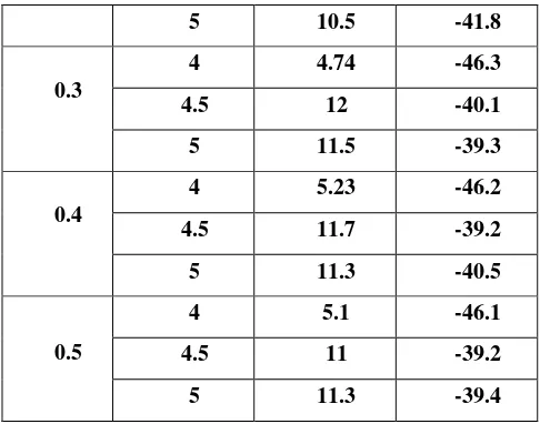
Table 4.5 SEMTEX material size 3×3cm Distance
(m)
Resonant frequency
(GHz)
E-field (dBV/m)
H-field (dBA/m)
0.1
4 5.5 -44.8
4.5 12.3 -38.3
5 7.28 -43.5
0.2
4 5.35 -45.2
5 10.5 -41.8
0.3
4 4.74 -46.3
4.5 12 -40.1
5 11.5 -39.3
0.4
4 5.23 -46.2
4.5 11.7 -39.2
5 11.3 -40.5
0.5
4 5.1 -46.1
4.5 11 -39.2
5 11.3 -39.4
Table 4.5 shows the E-field radiated by the antenna in presence of SEMTEX material with size 3cm. The E-field value gets reduced when the SEMTEX material is present due to the destruction of radiation.
Table 4.6 SEMTEX material size 2×2cm Distance
(m)
Resonant frequency
(GHz)
E-field (dBV/m)
H-field (dBA/m)
0.1
4 5.53 -43.2
4.5 12 -38.1
5 7.16 -43.2
0.2
4 5.27 -45.4
4.5 11.5 -38.2
5 9.41 -40.2
0.3
4 4.39 -45.2
4.5 11 -38.4
5 11.3 -39.2
0.4
4 5.19 -45.2
4.5 11.2 -39.1
5 11.1 -41.3
0.5
4 4.82 -46
4.5 11 -38.7
5 11.1 -38.2
Table 4.6 shows the E-field radiated by the antenna in presence of SEMTEX material with size 2cm. The E-field value gets reduced when the SEMTEX material is present due to the destruction of radiation.
5. CONCLUSION
Different Rectangular printed antennas using FR4 material were designed and performance of those antennas were analyzed with various parameters such as gain, directivity, VSWR and return loss. Various structures like RMPA without slots, vertical slot, double horizontal slot and centre slot were proposed. From the performance analysis, Double horizontal slot provides maximum gain (8.61dB), maximum directivity (5.82dBi), minimum VSWR (1.0451) and minimum return loss (-33.918dB). Thus the double horizontal slot antenna produce the better result than the other antennas. Based on the E-field of RMPA the SEMTEX explosive material is detected. When the absence SEMTEX material E-field value is 18.2 dBV/m which is reduced in presence of SEMTEX material. In future work, the proposed antenna will be further developed for the same explosive detection application. ACKNOWLEDGEMENTS
At first, I thank Lord Almighty to give knowledge to complete the survey. I would like to thank my colleagues, family and friends who encouraged and helped us in preparing this paper.
REFERENCES
[1]Aditi Sharma, Vivek K. Dwivedi, and G. Singh (2008),
“THz Rectangular Patch Microstrip Antenna Design Using Photonic Crystal as Substrate” Progress In Electromagnetics Research Symposium, vol. no.23, P.No 161-165.
[2]Alka, Devan Bhalla, Krishan Bansal(2009),
“Rectangular microstrip patch antenna in X-band for wireless applications” MIT International journal of Electronics and Communication Engineering Volume 1, No.1.
[3]S.Anscy(2013), “Slot Microstrip antenna for 2.4GHz RFID reader application”, International Journal of Advanced Research in Electronics and Communication Engineering (IJARECE) Volume 2, Issue 5.
[4]Bhavani Danana, Balamati Choudhury, R M Jha(2014),
“Design of High Gain Microstrip Antenna for THz Wireless Communication” International Journal of Advanced Research in Electrical, Electronics and Instrumentation Engineering Vol. 3, Special Issue 5.
[5]Bikash Ranjan Behera and Priyadarshi Suraj(2016),“Effect of Substrates on Metamaterial Based Antenna Design and Analysis of Antenna using Different Substrates”IEEE WiSPNET conference, 978-1-4673-9338 IEEE P.No 665-669.
Journal of Mechanical & Mechatronics Engineering IJMME-IJENS Vol:14 No:05, P.No 31-36.
[7]Devan Bhalla, Krishan Bansal(2013),“Design of a Rectangular Microstrip Patch Antenna Using Inset Feed Technique” IOSR Journal of Electronics and Communication Engineering (IOSR-JECE) Volume 7 Issue 4,P.No 08-13.
[8]Indrasen Singh and Dr. V.S. Tripathi(2011), “Micro strip Patch Antenna and its Applications: a Survey” International Journal Computer Technoloy Application, Vol 2 (5),P.No1595-1599.
[9]Kiran Jain and Keshav Gupta(2014), “Different Substrates Use in Microstrip Patch Antenna-A Survey” International Journal of Science and Research (IJSR) Volume 3 Issue 5,P.No 1802-1803.
[10]Menaka, Dr. V.S. Tripathi (2015), ” S-Shaped Microstrip Patch Antenna for Broadband Application Using Slotting Technique” International Journal Computer Technology Application Volume 55– No.18.
[11]Melzer, M., Karnaushenko, D., Lin, G., Baunack, S., Makarov, D. & Schmidt (2015), O. G.” Direct transfer of magnetic sensor devices to elastomeric supports for stretchable electronics” Adv. Mater. 27, ISSN:1333– 1338
[12]Payal Kalra, Prince and Ekambir Sidhu(2017),
“Terahertz Microstrip Patch Antenna Design for detection of Plastic Explosive SEMTEX”International Research Journal of Engineering and Technology (IRJET) Volume: 04 Issue: 0, P.No 1214-1217.
[13]Payal Kalra and Ekambir Sidhu(2017), “Microstrip patch antenna using FR4 as substrate for detection of riboflavin” International Research Journal of Engineering and Technology (IRJET)
[14]D.Pavithra , K.R.Dharani (2013) , “A Design of H-Shape Microstrip Patch Antenna for WLAN Applications”, International Journal of Engineering Science Invention, Volume 2, Issue 6.
[15] Prince, Payal Kalra,Ekambir Sidhu(2017), “Novel Terahertz Microstrip Patch Antenna for detection of L-ascorbic acid and Thiamine hydrochloride” International Journal of Engineering Trends and Technology (IJETT) – Volume 45 Number 5, P.No 215-218.
[16] RamaDevi. K, Mallikarjuna Prasad.A and Jhansi Rani(2012). A, “Design of A Pentagon Microstrip Antenna for Radar Altimeter Application International Journal of Web & Semantic Technology (IJWesT) Vol.3, No.4.
[17]Renu Kumari, Jharkhand Rai(2016), “To Study The Bandwidth Of Microstrip Antenna Using Artificial Neural Network” International Journal of Advanced Technology in Engineering and Science, Volume-4, Issues 6, pp 255-261.
[18]S.Sai Bharathwaj, K.Prakash, “Circular Polarisation Dual Feed Microstrip PatchAntenna with 3dB Hybrid Coupler for WLAN ”, International Journal of Engineering Science Invention ISSN (Online): 2319-6734, ISSN (2012).
[19]Simarjit Singh Saini, Tejinder Kaur Gill, Parth Kuchroo and Ekambir Sidhu(2016), “TeraHertz textile microstrip patch antenna design employing denim
substrate for detection of TNT
explosives”International Conference on Control, Computing, Communication and Materials (ICCCCM)
[20]Swagata B Sarkar(2017),”Design and Analysis of Annular Ring Triangular Microstrip Patch Antenna” Second International Conference On Computing and Communications Technologies(ICCCT’17) 978-1-5090-6221-8/17/ IEEE, P.No 21-26.
[21] J.Vanitha, N.Augustia(2016), “Design of Broadband Microstrip Patch Antenna Using Stack and Notch Techniques”, International Journal of Advanced Research in Computer Science and Software Engineering, Volume 6, Issue 2.