Experimental Study Of Slip In Haunched Gusset
Plate For Cold Formed Steel Connections
KM Aminuddin, Anis Saggaff, Mahmood Md Tahir, Shek Poi Ngian, Arizu Sulaiman, Muhammad Firdaus, Hanafiah, and Saloma
Abstract: Gusset plates for beam-to-column joints are the most common bolted connection solution. CFS beam column connections such as gusset plates can be developed in CFS double back-to-back channel sections with relatively high moment resistance. In this paper will investigated the failure mode of the slip-in connection CFS using haunched gusset plate that has 10 mm of thickness that occurs as a result of testing isolated joint tests and to compare the results of stiffness and strength between previous researchers with another type of gusset plate. The value of moment resistance (Mj) of the beam section C20024, C25024 and C30024 were 35.5 kNm, 41.65 kNm and 46.3 kNm respectively. The value of rotational stiffness (Sj,exp) of the beam section C20024, C25024 and C30024 were 520 kNm/rad, 590 kNm/rad and 610 kNm/rad respectively. The increase and decrease in moment capacity values and initial stiffness for the gusset plate connection are influenced by the thickness or shape of the gusset plate and the beam size. Index Terms: Connection, gusset plate, cold formed steel, moment resistance, stiffness
—————————— ——————————
1.
INTRODUCTION
Cold-formed steel sections are productive building materials in construction and are widely used as secondary structural components [1] such as roof purlines, medium-sized floor joints, wall panel studs, factory storage racking and construction site hoarding structures. [2]. The main advantages of CFS systems are light weight, simple installation on sites and prefabrication potential, resulting in low cost [3]. Thin-walled behavior limits the structural performance of CFS sections by premature buckling and instability [4]. One solution for avoiding premature local failures and ensuring ductility in connected CFS connections is to mobilize bolt slip and bearing behavior while beams and columns remain elastic. The cold-formed steel structures have a wide variety of welded and bolted connections Due to simpler assembly, connected connections are commonly used on construction sites [3, 5]. Gusset plates for beam-to-column joints are the most common bolted connection solution. CFS beam column connections such as gusset plates can be formed in CFS double back-to-back channel sections with relatively high moment resistance [6]. The previous research of the bolted gusset plate connections for CFS has been done by Bučmys [3, 5], Tan [7, 8] and Aminuddin [9, 10]. The study of Bučmys was carried out using mathematical models with Ansys 14.0 software with two different forms of gusset plates (i.e. type A and type B). The thicknesses of the gusset plate were 6 mm and 12 mm. the numerical result said that changing the type of gusset plate from type A to type B was decrease the rotation. Tan’s experiment [7, 8] using two cold-formed lipped channel sections were placed back-to-back and slip-in connection 6 mm of thickness hot-rolled steel gusset plate. It is observed from the experimental results that the joint moment resistance ratio to the beam moment resistance increases in the range of 0.46 to 0.70. The joint rotational
capacity exceeds 30 mRad. The rotational stiffness is 511 kNm / rad to 1671 kNm / rad. Aminuddin [9, 10] also conducted research on the CFS connection with a 6 mm thick rectangular gusset plate. The study used a beam size of C20019 and column C30024 with the isolated joint test method. The results of the study were obtained that the moment of experimentation and stiffness were 15.68 kNm and 327 kNm / rad, respectively. Previous studies have not yet implemented the type of slip in gusset plate connection with haunched shapes with different beam sizes. In this paper will investigated the failure mode of the slip-in connection CFS using haunched gusset plate that has 10 mm of thickness that occurs as a result of testing isolated joint tests and to compare the results of stiffness and strength between previous researchers with another type of gusset plate.
2 EXPERIMENTAL PROCEDURES
2.1 Preparation of specimens
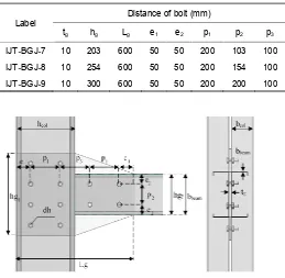
The material properties in this paper used a double-lipped channel C-section that connected back-to-back to prevent local distortion. [11]. The column used only one C300 profile with a height of 3 m and a beam length of 1 m. The beam profiles (see Table 1) were used with grade 350 N / mm2 C200, C250 and C300 based on [12]. The detail of bolts configuration see Fig. 1 that based on range validity according to the Eurocode 3. The bolts using M12 Grade 8.8 with 12 mm of bolt holes diameter with yield strength (fy = 640 MPa) and tensile ultimate strength (fu = 800 MPa) refer to Firdaus [13]. The connector of beam and column using slip in haunched gusset plate grade S275 with 10 mm thickness and will be located on 1.5 m from column base. The specimens will be named IJT-BGJ-7 for C20024 beam section, IJT-BGJ-8 for C25024 beam section, and IJT-BGJ-9 for C30024 beam section that can be shown in Table 2 and Table 3. The detail of dimension haunched gusset plate was presented in Fig. 2 and Table 4.
————————————————
KM Aminuddin is PhD. student of Civil Engineering, Faculty of Engineering, Sriwijaya University, Indonesia. Corresponding Email:
km_aminuddin@student.pps.unsri.ac.id
Anis Saggaff, Hanafiah, and Saloma Civil Engineering Department, Faculty of Engineering, Sriwijaya University, Indonesia.
Mahmood Md Tahir, Shek Poi Ngian and Arizu Sulaiman, Construction Research Centre (CRC), Faculty of Engineering, Universiti Teknologi Malaysia, 81310 Skudai, Johor Bahru, Malaysia
4954 TABLE1
CROSS SECTION DIMENSION
Profile Dimension (mm)
Web Flange Lip Thickness Radius
C20024 203 76 15.5 2.4 5
C25024 254 76 20.5 2.4 5
C30024 300 96 27.5 2.4 5
TABLE2
CONFIGURATION DETAIL OF SPECIMEN
Label Beam Column Number of Bolt
IJT-BGJ-7 C20024
C30024 12
IJT-BGJ-8 C25024 12
IJT-BGJ-9 C30024 12
TABLE3
CONFIGURATION DETAIL OF HAUNCHED GUSSET PLATE CONNECTION
Label
Distance of bolt (mm)
tg hg Lg e1 e2 p1 p2 p3 IJT-BGJ-7 10 203 600 50 50 200 103 100 IJT-BGJ-8 10 254 600 50 50 200 154 100 IJT-BGJ-9 10 300 600 50 50 200 200 100
Fig. 1. Configuration of haunched gusset plate (HG) connection
TABLE4
THE DIIMENSION OF SLIP IN HAUNCHED GUSSET PLATE
IJT-BGJ-7 IJT-BGJ-8 IJT-BGJ-9
Lg = 600 mm Lgc = 300 mm Lgb = 300 mm hgc = 409 mm hgb= 203 mm hgb1= 103 mm
Lg = 600 mm Lgc = 300 mm Lgb = 300 mm hgc = 550 mm hgb= 254 mm hgb1= 148 mm
Lg = 600 mm Lgc = 300 mm Lgb = 300 mm hgc = 550 mm hgb= 300 mm hgb1= 125 mm
.
Fig. 2. Detail of haunched gusset plate
2.2 Method of research
The samples were tested using full-scale isolated joint test (IJT) at the Constructions Research Center (CRC) Universiti Teknologi Malaysia (UTM). The testing is installed in Magnus frame with several testing tools i.e. linear variable displacement transducer (LVDT) and inclinometers (Inc) (Fig 3).
Fig. 3. The layout for isolated joint testing
There are several testing tools that must be installed (Fig. 3): a) The load cell and hydraulic jack were located at the end
of the beam. Each specimen is loaded around 0.2 – 0.5kN gradually.
b) Lateral restraint useful to avoiding excessive torsion of the beam
c) Inclinometer provided the beam rotation, approximately 100 mm from the column of the flange5 unit LVDT (Variable Linear Differential Transformer) that located in: LVDT 1 (under load cell); LVDT 2 (500 mm from flange column); LVDT 3 (100 mm from flange column) and LVDT 4-5 (web column). LVDT will be recorded via data logger.
All specimens have been tested until the mode of failure is indicated such as:
1. The mode of failure or yield at the column of the flange. 2. Buckling behavior in the column of the flange.
3 RESULTS AND DISCUSSION
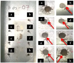
3.1 Failure modes of specimens
The failure mode to be explained is only the C20024 beam section and the other specimen will be listed in the table. The failure mode of the connection happened when 35.5 kN load was applied see Fig 4. The local bending was take place at the column in compression zone where the rotation due to stress concentration at the center of flange. Fig 5a presented the local bending at the column flange and Fig 5b showed that bottom of the beam flange was deformation at the bolt hole that located in column web. This deformation occurs because of the tangential force that exceed 35.5 kN, thus the resistance of column cannot exceed by 35.5 kN (Fig 6).
Fig. 4. The deformation of specimens
Fig. 5. Column (a) and beam (b) failure mode in the compression area.
TABLE5
THE FAILURE MODE OF ALL SPECIMEN
Specimen Failure mode identification IJT-BGJ-7,
IJT-BGJ-8, IJT-BGJ-9
1) Bolt bearing in beam column and haunched gusset plate
2) The column flange has bending in compression zone
3) The beam flange has bending in compression zone
Fig. 6. The bolt hole failure mode at column
3.2 Moment versus rotation curve
Fig. 7 until Fig. 9 was presented the momen rotation curve using haunched gusset plate at specimen BGJ-7, IJT-BGJ-8 and IJT-BGJ-9. Fig. 8 showed the value of momen capacity (Mj,exp) for IJT-BGJ-7 was 35.5 kNm, the value of initial stiffness (Sj,exp) was 520 kNm/rad and the rotational maximum was 0.059 rad.
Fig. 7. Moment-rotation curve (M -∅) IJT-BGJ-7 for C20024 beam section
Fig. 8 showed that the value of capacity moment (Mj,exp) for IJT-BGJ-8 was 41.65 kNm with 590 kNm/rad initial stiffness and 0.058 rad of rotation. Fig. 9 for IJT-BGJ-9 has 46.3 kNm of the moment capacity (Mj,exp) and 650 kNm/rad of the initial stiffness (Sj,exp).
Fig. 8. Moment-rotation curve (M -∅) IJT-BGJ-8 for C25024 beam section
Mj,u,exp = 35,5
ø
j,u
,e
xp
=
0
,0
5
9
ø
j,0
,0
3
,e
xp
=
0
,0
3
Mj,0,03,exp = 22,5
Sj,Exp = 520
0 5 10 15 20 25 30 35 40
0 0.02 0.04 0.06
M
j (
kN
m
)
∅j (rad)
Mj,u,exp = 41.65
ø
j,u
,e
xp
=
0
,0
5
8
ø
j,0
,0
3
,e
xp
=
0
,0
3
Mj,0,03,exp = 26,277
Sj,Exp = 590
0 5 10 15 20 25 30 35 40 45
0 0.02 0.04 0.06
M
j (
kN
m)
4956 Fig. 9. Moment-rotation curve (M -∅) IJT-BGJ-9 for C30024
beam section
TABLE6
THE COMPARISON BETWEEN SPECIMENS
Specimens Mj,exp (kNm) Ratio of Mj,exp
Sj,exp (kNm/ra d)
Ratio of Sj,exp
Rotation (rad) IJT-BGJ-7
Beam :
C20024 35.5 1.00 520 1.00 0.059
IJT-BGJ-8 Beam : C25024
41.65 1.17 590 1.13 0.058
IJT-BGJ-9 Beam : C30024
46.3 1.30 650 1.25 0.053
Table 6 shows the comparison of the moment experiment and stiffness against beam size. The ratio of moment experiment was increase 1.00 - 1.30 while the ratio of stiffness was increase 1.00 - 1.25. This is shows that the influence of the beam size on the moment joint capacity and also the stiffness of the connection. The high beam size greatly influences the inertia of the beam so that it can resist the very large moment. The specimen IJT-BGJ-7 until IJT-BGJ-9 have more than 0.03 rad of rotation, therefore categorized into ductile connections.
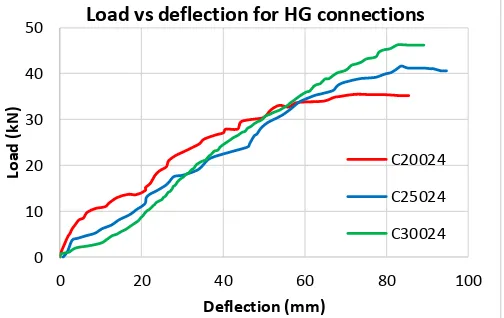
3.4 Load versus deflection
The load was applied in steps of 0.2kN using a hydraulic jack until the specimen reached a condition of failure. When the graph load vs deflection reaches its limit, the maximum load is reached until it decreases. The deflection maximum was located in the 1, so the deflection value was used LVDT-1 for load vs deflection curve.
Fig. 10. Load vs deflection curve for haunched gusset plate connection
Fig. 11. Load vs deflection phase curve for haunched gusset plate connection
Fig. 10 show load vs deflection curve of haunched gusset plate (HG) for BGJ-7 to BGJ-9 specimens. The IJT-BGJ-7 has the maximum deflection 72.89 mm when the load achieved 35.5 kN. The IJT-BGJ-8 has the maximum deflection 83.7 mm when the load achieved 41.65 kN. The IJT-BGJ-9 has the maximum deflection 83.33 mm when the load achieved 46,3 kN. From the graph, it can be seen that the influence of the beam size on the load and deflection. the size of the beam also affects the dimensions of the haunched gusset plate so as to increase the resistance to the load. Graph load vs deflection (Fig.11) has several phase changes according to the graph slope ie:
1. The phase 1 shows the condition of the beam deforms that given by load. This is indicated by the increase slope of the curve.
2. The phase 2 shows the connection element has reacted where the haunched gusset plate has slipped and the bolt has bearing resistance of the bolt hole. This condition is indicated by a decreasing slope of curve.
3. The phase 3 shows that the failure mode has occurred because it has reached the moment resistance of joint.
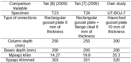
3.3 Discussion
From the experiment result of moment capacity and initial stiffness can be seen in the Table 7 and Table 8. The comparison results in Table 7 show that for haunched gusset
Mj,u,exp = 46,3
ø
j,u
,e
xp
=
0
,0
5
3
ø
j,0
,0
3
,e
xp
=
0
,0
3
Mj,0,03,exp = 34,885
Sj,Exp = 650
0 5 10 15 20 25 30 35 40 45 50
0 0.02 0.04 0.06
M
j (
kN
m)
∅j (rad)
0 10 20 30 40 50
0 20 40 60 80 100
Lo
ad
(k
N
)
Deflection (mm)
Load vs deflection for HG connections
C20024
C25024
plate connection types have the greatest moment capacity (Mj,exp) value and initial stiffness (Sj,exp) compared to other connection type models. The value of the moment capacity of the haunched gusset plate connection increased by 147.37% (from 14.27 kNm to 35.3 kNm) to the value of the moment capacity of the rectangular gusset plate while the initial stiffness value was 71.62% (from 303 kNm / rad to 520 kNm / rad). The moment capacity relation between the rectangular gusset plate and the flange cleat connection increased by 78.28% (from 19.8 kNm to 35.5 kNm) while the initial stiffness value increased by 48.15% (from 351 kNm / rad to 520 kNm / rad).
TABLE7
THE RESULT COMPARISON MOMENT-ROTATION OF C20024 BEAM SECTION
Comparison Variable
Tan [8] (2009) Tan [7] (2009) Own study
Specimen T23 T24 IJT-BGJ-7
Type of onnections Rectangular gusset plate 6
mm of thickness
Rectangular gusset plate +
flange cleat 6 mm of thickness
Haunched gusset plate
10 mm of thickness Column depth
(mm) 250 250 300
Beam depth (mm) 200 200 200
Mj(exp) kNm 14.27 19.8 35.3
Sj(exp) kNm/rad 303 351 520
Table 8 presented that the comparison of haunched gusset plate connection type with rectangular gusset plate connection type has increased moment capacity value of 83.18% (from 22.74 kNm to 41,65 kNm) while the initial stiffness value increases 6.7% (from 553 kNm / rad to 590 kNm / rad). When compared with the connection type of the combination of rectangular gusset plate and flange cleat there was an increase of 34.45% (from 30.98 kNm to 41,655 kNm) moment capacity value and the initial stiffness value decreased by 21.3% (from 750 kNm / rad to 590 kNm / rad).
TABLE8
COMPARISON MOMENT-ROTATION OF C25024 BEAM SECTION
Comparison Variable
Tan [8] (2009) Tan [7] (2009) Own study
Specimen T25 T26 INT-BGJ-8
Type of onnections Rectangular gusset plate 6
mm of thickness
Rectangular gusset plate +
flange cleat 6 mm of thickness
Haunched gusset plate
10 mm of thickness Column depth
(mm)
250 250 300
Beam depth (mm) 250 250 250
Mj(exp) kNm 22.74 30.98 41.65
Sj(exp) kNm/rad 553 750 590
4 CONCLUSION
The experiment result produced a moment-rotation curve that was compared by previous researcher. This paper allows us to draw the following conclusions:
1) Some of the specimen had the same failure mode : a. Bolt bearing in beam, column and haunched gusset
plate
b. The column flange has bending in compression zone
c. The beam flange has bending in compression zone 2) The moment of joint (Mj) of the beam section C20024,
C25024 and C30024 were 35.5 kNm, 41.65 kNm and 46.3 kNm respectively.
3) The rotational stiffness (Sj,exp) of the beam section C20024, C25024 and C30024 were 520 kNm/rad, 590 kNm/rad and 610 kNm/rad respectively.
4) The increase and decrease in moment capacity values and initial stiffness for the gusset plate connection are influenced by the thickness or shape of the gusset plate and the beam size.
ACKNOWLEDGMENTS
This research was funded by Sriwijaya University and Research Center for Construction, Universiti Teknologi Malaysia (UTM-CRC). The author would like to thank its supervisors Professor Anis Saggaff and Professor Mahmood MD Tahir for their support and support in this work.
REFERENCES
[1] H. Ho and K. Chung, "Practical design of cold-formed steel Z sections with lapped connections," in Advances in Steel Structures (ICASS'02), ed: Elsevier, 2002, pp. 445-452.
[2] M. Wong and K. Chung, "Structural behaviour of bolted moment connections in cold-formed steel beam-column sub-frames," Journal of Constructional Steel Research, vol. 58, pp. 253-274, 2002.
[3] Ž. Bučmys and G. Šaučiuvėnas, "The behavior of cold formed steel structure connections," Engineering Structures and Technologies, vol. 5, pp. 113-122, 2013. [4] Y. H. Lee, C. S. Tan, S. Mohammad, M. M. Tahir, and P.
N. Shek, "Review on cold-formed steel connections," ScientificWorldJournal, vol. 2014, p. 951216, 2014. [5] Ž. Bučmys and A. Daniūnas, "Analytical and experimental
investigation of cold-formed steel beam-to-column bolted gusset-plate joints," Journal of Civil Engineering and Management, vol. 21, pp. 1061-1069, 2015.
[6] A. Bagheri Sabbagh, M. Petkovski, K. Pilakoutas, and R. Mirghaderi, "Experimental work on cold-formed steel elements for earthquake resilient moment frame buildings," Engineering Structures, vol. 42, pp. 371-386, 2012.
[7] T. C. Siang, "Behaviour of pin and partial strength beam-to-column connections with double channel cold-formed steel sections," ed: Universiti Teknologi Malaysia, 2009. [8] C. S. Tan, M. M. Tahir, P. N. Shek, and A. B. H. Kueh,
"Experimental Investigation on Slip-In Connection for Cold-Formed Steel Double Channel Sections," Advanced Materials Research, vol. 250-253, pp. 1038-1041, 2011. [9] K. Aminuddin, A. Saggaff, and M. M. Tahir, "Experimental
behaviour of beam-column connection using cold-formed steel sections with rectangular gusset-plate," in AIP Conference Proceedings, 2017, p. 020006.
[10] K. Aminuddin, A. Saggaff, and M. M. Tahir, "Structural Behaviour Of Slip-In Gusset Plate Connection For Double Lipped Channel Cold Formed Steel Using Partial Strength Connection."
4958
[12] B. Standard, "BS EN 1993-1-3:2006 - Eurocode 3 : Design of steel structures : Part 1-3: General rules : Supplementary rules for cold-formed members and sheeting," ed, 2006.