IJEDR1702226
International Journal of Engineering Development and Research (www.ijedr.org)1444
Implementation of drive kinematics for a self-driving
car
Deriving and implementing equations for steering and electronic differential in Robot
Operating System
1
Sudhanva S,
2Dr K R Prakash,
3Balaji Sunil Kumar
1Student, 2Professor, 3Senior Architect 1Mechanical Engineering Department,
1The National Institute of Engineering, Mysore, India
________________________________________________________________________________________________________ Abstract—The paper spells out the derivation and implementation of mathematical models which provide steering angle required and differential speed calculation for each wheel in a car-like mobile robot which gratify for both Ackermann Steering and Four-Wheel steering. The models are simulated and is validated and verified by simulation of different maneuvers for different vehicle speeds in Gazebo before testing on a real vehicle which is later found to match the precision.
Index Terms— ROS, Robot Operating System, steering angle, electronic differential, self-driving car, autonomous robots,
car like mobile robot, Instantaneous Centre of Rotation, ICR.
________________________________________________________________________________________________________
I.INTRODUCTION
The most conventional steering arrangement is to turn the front wheels using a hand–operated steering wheel which is positioned in front of the driver, via a steering column, which may contain universal joints (which may also be part of the collapsible steering column design), to allow it to deviate somewhat from a straight line. Other arrangements are sometimes found on different types of vehicles, for example, a tiller or rear–wheel steering. Tracked vehicles such as bulldozers and tanks usually employ differential steering — that is, the tracks are made to move at different speeds or even in opposite directions, using clutches and brakes, to bring about a change of course or direction.
The basic aim of steering is to ensure that the wheels are pointing in the desired directions. This is typically achieved by a series of linkages, rods, pivots and gears. The steering linkages connecting the steering box and the wheels usually conform to a variation of Ackermann steering geometry, to account for the fact that in a turn, the inner wheel is actually travelling a path of smaller radius than the outer wheel, so that the degree of toe suitable for driving in a straight path is not suitable for turns. The angle the wheels make with the vertical plane also influences steering dynamics as do the tires.
Four-wheel steering is a system employed by some vehicles to improve steering response, increase vehicle stability while maneuvering at high speed and to decrease turning radius at low speed.
In automotive engineering, the electronic differential is a form of differential, which provides the required torque for each driving wheel and allows different wheel speeds It is used in place of the mechanical differential in multi-drive systems. When cornering the inner and outer wheels rotate at different speeds, because the inner wheels describe a smaller turning radius. This happens because of the separation between the wheels called as wheelbase and track width. In other words, when a car is moved in a circular path, the car draws four circles in case of two-wheel steering and two circles in case of four-wheel steering. In order to stabilize the vehicle and avoid unnecessary wear and tear of the tires, the rotational speeds of the wheels are to be varied slightly with respect to each other. The electronic differential uses the steering wheel command signal and the motor speed signals to control the power to each wheel so that all wheels are supplied with the torque they need.
The navigation module considers the vehicle as an object ignoring its dynamics. The dynamics are then considered while taking action at the lower levels. With above facts said, the navigation module portrays only the linear and angular velocities at which the vehicle has to move. With these two data being delivered, steering angle is computed along with the differential speed.
II.LITERATURE REVIEW
IJEDR1702226
International Journal of Engineering Development and Research (www.ijedr.org)1445
PowertrainAccording to Shigeyuki Yoshihara et al, generally, in most electric vehicle (EV) propulsion applications, an AC motor is connected mechanically to the wheels by reduction gears and a mechanical differential, as shown in Figure 1. [1]
Fig 1: The above figure depicts motor connected to mechanical differential.
According to Bekheira Tabbache
et al, a
lso in some vehicle drive arrangements, high-speed, low-torque wheel motors necessitating gear reduction are employed, and in these cases, either a gear motor assembly is mounted inside the wheel, or a chassis mounted motor is connected to the wheel through gear reduction. Further simplification of the vehicle drive arrangement results in the purging of the gear being interposed between motor and wheel by employing in-wheel motors. The Figure 2 depicts in-wheel motors. The above then calls for the use of an electric differential.[2]Fig 2: In-wheel motor
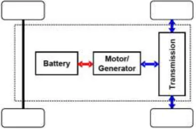
Certain Electric vehicles with independent all-wheel drive powertrain will be equipped with Variable Frequency Drives (VFD) which run on AC supply. The torque and speed of these VFDs are varied by varying the frequency in supplying the electric supply. This is on the fact that at low frequency, torque will be high and speed will be low and vice versa. In case of manually operated vehicle, devices like potmeters are used to vary the frequency, which in turn varies proportionally the torque and speed. While in case of self-driven vehicles, the frequency is varied with the help of a AC Speed Controller. In order to employ AC motors, the vehicle’s DC supply is converted to AC and pipelined to the drives as shown in Figure 3. [1]
Fig 3: The above figure depicts the process flow of controlling the wheel rotation using VFD.
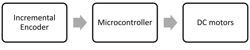
According to Yafei Wang et al, electric vehicles can be implemented with four in-wheel independent motors. [3] Vehicles with independent all-wheel drive powertrain, some will be equipped with DC motors which run on DC supply. The torque and
IJEDR1702226
International Journal of Engineering Development and Research (www.ijedr.org)1446
speed on these DC motors are varied by means of a H-bridge or a motor controller. The motor controller increases the current when torque is required. The decision of increasing current is made with the help of incremental encoder. Incremental encoder outputs the wheel rotation, based on its output, if the wheel is not rotating, the motor controller increases current to increase torque. To get a precise wheel rotation, PWM will be supplied from a microcontroller to motor controller. The sequence diagram is as shown in Figure 4.Fig 4: The above figure depicts the process flow of controlling the wheel rotation using DC motors.
According to
Bekheira Tabbache et al
, ED-based EVs have advantages over classical EVs with a central motor. Indeed, mounting the motors directly to the wheels simplifies the mechanical layout. The ED system will reduce the drive line components, thus improving the overall reliability and efficiency. This option will also reduce the drive line weight since mechanical differential and gear reduction are not used. However, one of the main issues in the design of these EVs (without mechanical differential) is to ensure vehicle stability in particular while cornering or under slippery road conditions. This calls for a specific traction control system. [4]Steering
According to Xiaodong Wu et al, in traditional EVs, a steering mechanism is obligatory for the turn motion. Nonetheless, by using the merit of individual wheel traction motors on the electric drive vehicles, it opens up the possibility of using a differential speed steering systems. A simple scheme is shown in Figure 5. Since gearbox, retarder, transmission and steering mechanism are called off from the four in-wheel motors independent drive vehicle or chassis mounted motors independent drive vehicle. Using four motors independently to drive vehicle, the steering of the vehicle is achieved by the differential speed controls on four wheels. The minimum turning radius of differential speed steering can be zero when a when on axis rotation is performed, which is impossible by traditional steering method.
Differential speed steering is extensively employed in the navigation of mobile robot. Due to undistinguishable steering mechanisms, wheeled and tracked skid-steered vehicles share many properties. Many of the difficulties associated with modelling and operating in these kinds of skid-steered vehicles arise from the complex contact between wheel and terrain. For Ackerman-steered vehicles as shown in Figure 5, the wheel motions may often be accurately modelled by pure rolling, while for differential-steered vehicles, in general, are modelled by curvilinear motion, the wheels roll and slide at the same time. This makes it difficult to develop kinematic and dynamic models, which accurately designate the motion characteristic. Vehicle can be steered through differential braking which is to get a speed difference in similar thought. [4]
Incremental
IJEDR1702226
International Journal of Engineering Development and Research (www.ijedr.org)1447
Fig 5: Two kinds of steering methods. Left depicts Ackermann steering. Right depicts differential steering.
Ackermann steering is the steering mechanism implemented in all the cars running on road. With this mechanism, the inner wheel turns more than the outer wheel towards the Instantaneous Centre of Rotation (ICR) as inner wheel covers less distance compared to the outer wheel. ICR is an imaginary point about which the car takes a turn as shown in Figure 6.
Fig 6: Figure depicts the Ackermann steering mechanism.
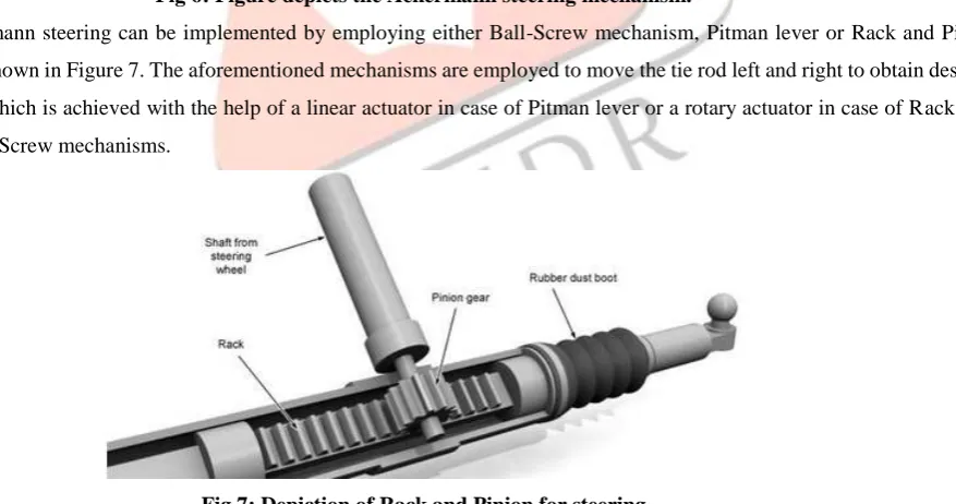
Ackermann steering can be implemented by employing either Ball-Screw mechanism, Pitman lever or Rack and Pinon mechanism as shown in Figure 7. The aforementioned mechanisms are employed to move the tie rod left and right to obtain desired steering angle which is achieved with the help of a linear actuator in case of Pitman lever or a rotary actuator in case of Rack and Pinion and Ball-Screw mechanisms.
Fig 7: Depiction of Rack and Pinion for steering
The steering mechanisms are generally implemented for front wheels only. Nevertheless, to take a sharper and shorter turn during cornering and high speed maneuvers, the same can be replicated to rear wheels to obtain four-wheel steering.
Outcome of Literature review
IJEDR1702226
International Journal of Engineering Development and Research (www.ijedr.org)1448
of the base platform, chassis mounted motors with gear reduction mechanism is employed. Since the chosen motor is a DC motor, it is driven by open source motor controllers controlled by a Arduino Mega.According to the present theories and practices, there are numerous ways of implementing steering mechanisms. While considering the weight of the vehicle, differential steering will not suffice. Also, due to the curvilinear motion, the odometry feedback calculation will vary. Hence, by employing Pitman lever mechanism, steering is actuated for both front as well as rear wheels. A linear actuator is employed to actuate the Pitman arm and a rotary encoder to have a feedback from steering.
III.DERIVATION
The equations below are derived as per the following assumptions,
The value of Linear Velocity is known at a given instant.
The value of Agular Velocity is known at a given instant.
The value of Wheelbase is known which is a constant. Since, the length of the car cannot change.
The value of Trackwidth is known which is a constant. Since, the width of the car cannot change.
The value of vehicle’s wheel diameter is known which is a constant.
As per Robotics Right Hand Rule, Turning Radius is Negative for Right Turn and Positive for Left Turn. Hence, θ value is negative for Right Turn and Positive for Left Turn.
Deriving equations for Electronic Differential in Ackermann Steering
Fig 8: Parameters and variables used in derivation for Ackermann Steering.
The below equations are derived with reference to Figure 8 First, turning radius is computed from Linear and Angular velocity
𝑇𝑢𝑟𝑛𝑖𝑛𝑔 𝑅𝑎𝑑𝑖𝑢𝑠 = 𝐿𝑖𝑛𝑒𝑎𝑟 𝑉𝑒𝑙𝑜𝑐𝑖𝑡𝑦
𝐴𝑛𝑔𝑢𝑙𝑎𝑟 𝑉𝑒𝑙𝑜𝑐𝑖𝑡𝑦
(1) Where Linear Velocity and Angular Velocity are obtained from navigation stack the displacement of rear wheel joints along the arc drawn about ICR as the center is calculated using the below equation,
𝐷𝑖𝑠𝑝𝑙𝑎𝑐𝑒𝑚𝑒𝑛𝑡 = (𝑇𝑢𝑟𝑛𝑖𝑛𝑔 𝑅𝑎𝑑𝑖𝑢𝑠 ± 𝑡𝑟𝑎𝑐𝑘𝑤𝑖𝑑𝑡ℎ/2) × 𝐴𝑛𝑔𝑢𝑙𝑎𝑟 𝑉𝑒𝑙𝑜𝑐𝑖𝑡𝑦 (2)
Where, Turning Radius is obtained from (1) in Meters Angular Velocity is obtained from navigation stack in Radians per Second The sign in equation (2) changes based on the position of the wheel.
From Figure 8,
(𝑇𝑢𝑟𝑛𝑖𝑛𝑔 𝑅𝑎𝑑𝑖𝑢𝑠 + 𝑡𝑟𝑎𝑐𝑘𝑤𝑖𝑑𝑡ℎ/2) is used for outer wheel.
(𝑇𝑢𝑟𝑛𝑖𝑛𝑔 𝑅𝑎𝑑𝑖𝑢𝑠 − 𝑡𝑟𝑎𝑐𝑘𝑤𝑖𝑑𝑡ℎ/2) is used for inner wheel. The rotations required to cover the distance is calculated using the equation below,
𝑊ℎ𝑒𝑒𝑙 𝑅𝑜𝑡𝑎𝑡𝑖𝑜𝑛𝑠 =𝐷𝑖𝑠𝑝𝑙𝑎𝑐𝑒𝑚𝑒𝑛𝑡
𝑊ℎ𝑒𝑒𝑙 𝑅𝑎𝑑𝑖𝑢𝑠
(3)
IJEDR1702226
International Journal of Engineering Development and Research (www.ijedr.org)1449
Wheel Radius is the radius of the wheel in meters Wheel Rotations are commanding angles for each instant in Radians The distance between ICR and the inner wheel’s joint is calculated using Pythagorean theorem as mentioned below𝐼𝐶𝑅𝐼 = √𝑤ℎ𝑒𝑒𝑙𝑏𝑎𝑠𝑒2+ (𝑡𝑢𝑟𝑛𝑖𝑛𝑔 𝑟𝑎𝑑𝑖𝑢𝑠 −𝑇𝑟𝑎𝑐𝑘−𝑤𝑖𝑑𝑡ℎ
2 )
2
(4)
To calculate the displacement of front inner wheel joint along the arc drawn about ICR as the center is calculated using the below equation,
𝐷𝑖𝑠𝑝𝑙𝑎𝑐𝑒𝑚𝑒𝑛𝑡 = 𝐼𝐶𝑅𝐼 × 𝐴𝑛𝑔𝑢𝑙𝑎𝑟 𝑉𝑒𝑙𝑜𝑐𝑖𝑡𝑦 (5)
Where, Turning Radius is obtained from equation (4) in Meters Angular Velocity is obtained from navigation stack in Radians per Second The rotations required to cover the distance is calculated using the equation below,
𝑊ℎ𝑒𝑒𝑙 𝑅𝑜𝑡𝑎𝑡𝑖𝑜𝑛𝑠 =𝐷𝑖𝑠𝑝𝑙𝑎𝑐𝑒𝑚𝑒𝑛𝑡
𝑊ℎ𝑒𝑒𝑙 𝑅𝑎𝑑𝑖𝑢𝑠 (6) Where, Displacement calculated from the equation (5) in meters Wheel Radius is the radius of the wheel in meters Wheel Rotations are commanding angles for each instant in Radians The distance between ICR and the inner wheel’s joint is calculated using Pythagorean theorem as mentioned below
𝐼𝐶𝑅𝑂 = √𝑤ℎ𝑒𝑒𝑙𝑏𝑎𝑠𝑒2+ (𝑡𝑢𝑟𝑛𝑖𝑛𝑔 𝑟𝑎𝑑𝑖𝑢𝑠 +𝑇𝑟𝑎𝑐𝑘−𝑤𝑖𝑑𝑡ℎ
2 )
2 (7) To calculate the displacement of front inner wheel joint along the arc drawn about ICR as the center is calculated using the below equation,
𝐷𝑖𝑠𝑝𝑙𝑎𝑐𝑒𝑚𝑒𝑛𝑡 = 𝐼𝐶𝑅𝑂 × 𝐴𝑛𝑔𝑢𝑙𝑎𝑟 𝑉𝑒𝑙𝑜𝑐𝑖𝑡𝑦 (8)
Where, ICRO is obtained from (7) in Meters Angular Velocity is obtained from navigation stack in Radians per Second The rotations required to cover the distance is calculated using the equation below,
𝑊ℎ𝑒𝑒𝑙 𝑅𝑜𝑡𝑎𝑡𝑖𝑜𝑛𝑠 =𝐷𝑖𝑠𝑝𝑙𝑎𝑐𝑒𝑚𝑒𝑛𝑡
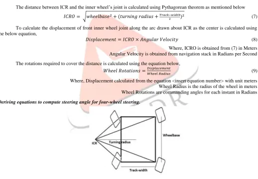
𝑊ℎ𝑒𝑒𝑙 𝑅𝑎𝑑𝑖𝑢𝑠 (9) Where, Displacement calculated from the equation <insert equation number> with unit meters Wheel Radius is the radius of the wheel in meters Wheel Rotations are commanding angles for each instant in Radians Deriving equations to compute steering angle for four-wheel steering.
Fig 9: Parameters and variables used in derivation for four-wheel Steering.
Turing Radius is first calculated using the equation (1) Let θ be the steering angle which is to be computed.
Assuming symmetry horizontally along the center of the vehicle, the steering angle for both front and rear steering angles remain same.
Therefore,
tan 𝜃 =
𝑤ℎ𝑒𝑒𝑙𝑏𝑎𝑠𝑒 2
IJEDR1702226
International Journal of Engineering Development and Research (www.ijedr.org)1450
tan 𝜃 = 𝑤ℎ𝑒𝑒𝑙𝑏𝑎𝑠𝑒
2×𝑡𝑢𝑟𝑛𝑖𝑛𝑔 𝑟𝑎𝑑𝑖𝑢𝑠 (11) Steering Angle θ is obtained by,
𝜃 = tan−1 𝑤ℎ𝑒𝑒𝑙𝑏𝑎𝑠𝑒
2×𝑡𝑢𝑟𝑛𝑖𝑛𝑔 𝑟𝑎𝑑𝑖𝑢𝑠 (12) Hence steering angle for front and rear wheels is given by,
𝑓𝑟𝑜𝑛𝑡 𝑤ℎ𝑒𝑒𝑙 𝑠𝑡𝑒𝑒𝑟𝑖𝑛𝑔 𝑎𝑛𝑔𝑙𝑒 = 𝑟𝑒𝑎𝑟 𝑤ℎ𝑒𝑒𝑙 𝑠𝑡𝑒𝑒𝑟𝑖𝑛𝑔 𝑎𝑛𝑔𝑙𝑒 = tan−1 𝑤ℎ𝑒𝑒𝑙𝑏𝑎𝑠𝑒
2×𝑡𝑢𝑟𝑛𝑖𝑛𝑔 𝑟𝑎𝑑𝑖𝑢𝑠 (13)
Deriving equations for electronic differential for four-wheel steering.
First the displacement of wheel joints along the arc drawn about ICR as the center is calculated using the below equation, 𝐷𝑖𝑠𝑝𝑙𝑎𝑐𝑒𝑚𝑒𝑛𝑡 = (𝑇𝑢𝑟𝑛𝑖𝑛𝑔 𝑅𝑎𝑑𝑖𝑢𝑠 ± 𝑇𝑟𝑎𝑐𝑘𝑤𝑖𝑑𝑡ℎ/2) × 𝐴𝑛𝑔𝑢𝑙𝑎𝑟 𝑉𝑒𝑙𝑜𝑐𝑖𝑡𝑦 (14)
Where, Turning Radius is obtained from equation (1) in Meters Angular Velocity is obtained from navigation stack in Radians per Second The sign in equation (14) changes based on the position of the wheel.
From Figure 9,
(𝑇𝑢𝑟𝑛𝑖𝑛𝑔 𝑅𝑎𝑑𝑖𝑢𝑠 + 𝑡𝑟𝑎𝑐𝑘𝑤𝑖𝑑𝑡ℎ/2) is used for outer wheel.
(𝑇𝑢𝑟𝑛𝑖𝑛𝑔 𝑅𝑎𝑑𝑖𝑢𝑠 − 𝑡𝑟𝑎𝑐𝑘𝑤𝑖𝑑𝑡ℎ/2) is used for inner wheel The rotations required to cover the distance is calculated using the equation below,
𝑊ℎ𝑒𝑒𝑙 𝑅𝑜𝑡𝑎𝑡𝑖𝑜𝑛𝑠 =𝐷𝑖𝑠𝑝𝑙𝑎𝑐𝑒𝑚𝑒𝑛𝑡
𝑊ℎ𝑒𝑒𝑙 𝑅𝑎𝑑𝑖𝑢𝑠 (15) Where, Displacement calculated from the equation (14) in meters Wheel Radius is the radius of the wheel in meters Wheel Rotations are commanding angles for each instant in Radians
IV.IMPLEMENTATION
Mechanically, the motors are housed on the chassis with gear reduction mechanism connected mechanically to the wheels. The steering mechanism is implemented using Pitman arm which is actuated using a linear actuator and assembled with a rotary encoder for feedback from steering.
IJEDR1702226
International Journal of Engineering Development and Research (www.ijedr.org)1451
Fig 10: High level design
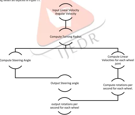
The module first takes in Linear and Angular velocities from Navigation module and computes Turning Radius using the equation (1). Steering Angle required is computed having known the value of Turning Radius and Wheelbase which is a constant using the equation (16) for Ackermann Steering mode and equation (12) for four-wheel steering mode. Following the computation, Steering Angle is given out as one of the outputs. On the other hand, Linear velocities for each wheel is computed. Having the Linear velocities for each wheel known, number of rotations required per second is calculated and given out as outputs. The detailed design for both the steering modes are depicted in Figure 11.
Fig 11: Detailed design of steering & differential module
Navigation
•Linear Velocity •Angular velocity
Steering & Differential
•Steering Angle •Turning Radius
•Wheel Rotations per second
Motor Driver
•PWM
•Steering Actuator
Steering Selection
•Ackermann Steering •Four-Wheel Steering
Input Linear Velocity
Angular Velocity
Compute Turning Radius
Compute Steering Angle
Output Steering angle
Compute Linear
Velocities for each wheel
joint
Compute rotations per
second for each wheel.
IJEDR1702226
International Journal of Engineering Development and Research (www.ijedr.org)1452
The objective of computing steering angle for a car-like mobile robot adhering to mobile robot kinematics with two-wheel steering is as mentioned below which is already derived and put to use in many of the car-like mobile robots,𝑠𝑡𝑒𝑒𝑟𝑖𝑛𝑔 𝑎𝑛𝑔𝑙𝑒 = tan−1 𝑤ℎ𝑒𝑒𝑙𝑏𝑎𝑠𝑒
𝑡𝑢𝑟𝑛𝑖𝑛𝑔 𝑟𝑎𝑑𝑖𝑢𝑠 (16) Equations (1) to (16) are implemented in Robot Operating System with C++ 11.
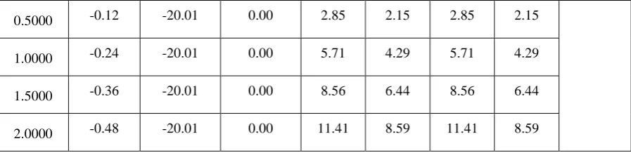
The observed data values for Ackermann steering are tabulated as follows in Table 1 and Table 2. The data from the Table 1 portrays that during Left Turn, the front right wheel covers maximum distance which is why it has higher rotations per second while rear left wheel has lowest rotations per second as it covers minimum distance. While Table 2 portrays that during Right Turn, the front left wheel covers maximum distance which is why it has higher rotations per second while rear right wheel has lowest rotations per second as it covers minimum distance.
Table 1: Data readings for Left Turn taken during the test run for Ackermann Steering. Command Velocity Steering Wheel Rotations
Turn [Linear Velocity] [Angular Velocity] Front wheels’ Steering Angle Rear wheels’ Steering Angle Front Left Wheel Speed Front Right Wheel Speed Rear Left Wheel Speed Rear Right Wheel Speed
mps radps Degrees Degrees rps rps rps rps
0.5000 0.00 0.00 0.00 2.50 2.50 2.50 2.50
Straight line motion
1.0000 0.00 0.00 0.00 5.00 5.00 5.00 5.00
1.5000 0.00 0.00 0.00 7.50 7.50 7.50 7.50
2.0000 0.00 0.00 0.00 10.00 10.00 10.00 10.00
0.5000 0.03 5.00 0.00 2.42 2.59 2.42 2.58
Left Turn
1.0000 0.06 5.00 0.00 4.85 5.19 4.83 5.17
1.5000 0.09 5.00 0.00 7.28 7.78 7.25 7.75
2.0000 0.12 5.00 0.00 9.70 10.38 9.66 10.34
0.5000 0.06 10.01 0.00 2.37 2.71 2.33 2.67
1.0000 0.12 10.01 0.00 5.31 7.73 3.42 6.58
1.5000 0.17 10.01 0.00 7.11 8.12 6.99 8.01
2.0000 0.23 10.01 0.00 9.48 10.83 9.32 10.68
0.5000 0.09 15.01 0.00 2.34 2.84 2.24 2.76
1.0000 0.18 15.01 0.00 4.68 5.68 4.48 5.52
1.5000 0.26 15.01 0.00 7.01 8.52 6.72 8.28
2.0000 0.35 15.01 0.00 9.35 11.36 8.96 11.04
IJEDR1702226
International Journal of Engineering Development and Research (www.ijedr.org)1453
1.0000 0.24 20.01 0.00 4.66 5.99 4.29 5.71
1.5000 0.36 20.01 0.00 7.00 8.98 6.44 8.56
2.0000 0.48 20.01 0.00 9.33 11.98 8.59 11.41
Table 2: Data readings for Right Turn taken during the test run for Ackermann Steering.
Command Velocity Steering Wheel Rotations
Turn [Linear
Velocity]
[Angular Velocity]
Front wheels’
Steering Angle
Rear wheels’
Steering Angle
Front Left Wheel
Speed
Front Right Wheel Speed
Rear Left Wheel Speed
Rear Right Wheel Speed
mps radps Degrees Degrees rps rps rps rps
0.5000 0.00 0.00 0.00 2.50 2.50 2.50 2.50
Straight line motion
1.0000 0.00 0.00 0.00 5.00 5.00 5.00 5.00
1.5000 0.00 0.00 0.00 7.50 7.50 7.50 7.50
2.0000 0.00 0.00 0.00 10.00 10.00 10.00 10.00
0.5000 -0.03 -5.00 0.00 2.42 2.59 2.42 2.58
Right Turn
1.0000 -0.06 -5.00 0.00 5.19 4.85 5.17 4.83
1.5000 -0.09 -5.00 0.00 7.78 7.28 7.75 7.25
2.0000 -0.12 -5.00 0.00 10.38 9.70 10.34 9.66
0.5000 -0.06 -10.01 0.00 2.71 2.37 2.67 2.33
1.0000 -0.12 -10.01 0.00 5.41 4.74 5.34 4.66
1.5000 -0.17 -10.01 0.00 8.12 7.11 8.01 6.99
2.0000 -0.23 -10.01 0.00 10.83 9.48 10.68 9.32
0.5000 -0.09 -15.01 0.00 2.84 2.34 2.76 2.24
1.0000 -0.18 -15.01 0.00 5.68 4.68 5.52 4.48
1.5000 -0.26 -15.01 0.00 8.52 7.01 8.28 6.72
2.0000 -0.35 -15.01 0.00 11.36 9.35 11.04 8.96
0.5000 -0.12 -20.01 0.00 2.99 2.33 2.85 2.15
IJEDR1702226
International Journal of Engineering Development and Research (www.ijedr.org)1454
1.5000 -0.36 -20.01 0.00 8.98 7.00 8.56 6.44
2.0000 -0.48 -20.01 0.00 11.98 9.33 11.41 8.59
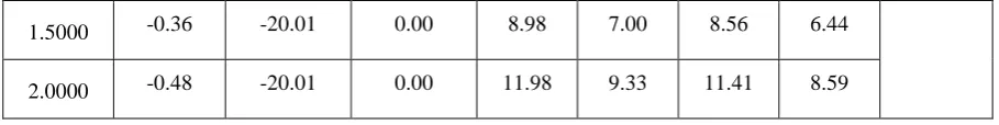
The observed data values for four-wheel steering are tabulated as follows in Table 3 and Table 4. The data from the Table 3 portrays that during Right Turn, the front left wheel and rear left wheel covers more distance which is why it has higher rotations per second while rear left wheel and front left wheel has lower rotations per second as it covers lesser distance comparatively. On the other hand, Table 4 portrays that during Left Turn, the front right wheel and rear right wheel covers more distance which is why it has higher rotations per second while rear left wheel and front left wheel has lower rotations per second as it covers lesser distance comparatively.
Table 3: Data readings for Right Turn taken during the test run for four-wheel Steering. Command Velocity Steering Wheel Rotations
Turn [Linear Velocity] [Angular Velocity] Front wheels’ Steering Angle Rear wheels’ Steering Angle Front Left Wheel Speed Front Right Wheel Speed Rear Left Wheel Speed Rear Right Wheel Speed
mps radps Degrees Degrees rps rps rps rps
0.5000 0.00 0.00 0.00 2.50 2.50 2.50 2.50
Straight line motion
1.0000 0.00 0.00 0.00 5.00 5.00 5.00 5.00
1.5000 0.00 0.00 0.00 7.50 7.50 7.50 7.50
2.0000 0.00 0.00 0.00 10.00 10.00 10.00 10.00
0.5000 -0.03 -5.00 0.00 2.42 2.58 2.42 2.58
Right Turn
1.0000 -0.06 -5.00 0.00 5.17 4.83 5.17 4.83
1.5000 -0.09 -5.00 0.00 7.75 7.25 7.75 7.25
2.0000 -0.12 -5.00 0.00 10.34 9.66 10.34 9.66
0.5000 -0.06 -10.01 0.00 2.67 2.33 2.67 2.33
1.0000 -0.12 -10.01 0.00 5.34 4.66 5.34 4.66
1.5000 -0.17 -10.01 0.00 8.01 6.99 8.01 6.99
2.0000 -0.23 -10.01 0.00 10.68 9.32 10.68 9.32
0.5000 -0.09 -15.01 0.00 2.76 2.24 2.76 2.24
1.0000 -0.18 -15.01 0.00 5.52 4.48 5.52 4.48
1.5000 -0.26 -15.01 0.00 8.28 6.72 8.28 6.72
IJEDR1702226
International Journal of Engineering Development and Research (www.ijedr.org)1455
0.5000 -0.12 -20.01 0.00 2.85 2.15 2.85 2.15
1.0000 -0.24 -20.01 0.00 5.71 4.29 5.71 4.29
1.5000 -0.36 -20.01 0.00 8.56 6.44 8.56 6.44
2.0000 -0.48 -20.01 0.00 11.41 8.59 11.41 8.59
Table 4: Data readings for Left Turn taken during the test run for four-wheel Steering.
Command Velocity
Combined steering
angle
Front Wheel Steering
Angle
Rear Wheel Steering
Angle
Wheel Speeds
Turn [Linear
Velocity]
[Angular Velocity]
Front Left Wheel
Front Right Wheel
Rear Left Wheel
Rear Right Wheel
mps radps Degrees Degrees Degrees radps radps radps radps
0.50 0.00 0.00 0.00 0.00 2.50 2.50 2.50 2.50
Straight Line Motion
1.00 0.00 0.00 0.00 0.00 5.00 5.00 5.00 5.00
1.50 0.00 0.00 0.00 0.00 7.50 7.50 7.50 7.50
2.00 0.00 0.00 0.00 0.00 10.00 10.00 10.00 10.00
0.50 0.03 5.00 2.50 2.50 2.42 2.59 2.42 2.59
Left Turn
1.00 0.06 5.00 2.50 2.50 4.84 5.17 4.84 5.17
1.50 0.09 5.00 2.50 2.50 7.25 7.76 7.25 7.76
2.00 0.12 5.00 2.50 2.50 9.67 10.35 9.67 10.35
0.50 0.06 10.01 5.00 5.00 2.34 2.68 2.34 2.68
1.00 0.12 10.01 5.00 5.00 3.90 6.86 3.90 6.86
1.50 0.17 10.01 5.00 5.00 7.02 8.04 7.02 8.04
2.00 0.23 10.01 5.00 5.00 9.36 10.72 9.36 10.72
0.50 0.09 15.01 7.50 7.50 2.26 2.78 2.26 2.78
1.00 0.18 15.01 7.50 7.50 4.53 5.56 4.53 5.56
1.50 0.26 15.01 7.50 7.50 6.79 8.34 6.79 8.34
2.00 0.35 15.01 7.50 7.50 9.06 11.12 9.06 11.12
0.50 0.12 20.01 10.01 10.01 2.19 2.89 2.19 2.89
IJEDR1702226
International Journal of Engineering Development and Research (www.ijedr.org)1456
1.50 0.36 20.01 10.01 10.01 6.58 8.67 6.58 8.67
2.00 0.48 20.01 10.01 10.01 8.77 11.55 8.77 11.55
V.CONCLUSION
This paper aspires to provide a baseline for developing a self-driving car with independent motors for each wheel eliminating the mechanical implementational overhead of differential gear mechanism. The derived mathematical models were implemented and tested in simulation and thus validated. Post validation, the same was implemented on a real vehicle and verified. Upon setting the goal, the vehicle steered towards the goal and reached without overshooting and undershooting. Also, it was observed from the feedback logs that the electronic differential is completely functional with values matching the calculated values. Hence the mathematical models are proved.
REFERENCES
[1] Shigeyuki Yoshihara Hiroshi Hamano Hiroyuki Yamada Kenichiro Nakajima “Development of Technology for Electrically Driven Powertrains in Hybrid Electric Vehicles”
[2] Bekheira Tabbache, Abdelaziz Kheloui, and Mohamed El Hachemi Benbouzid “An Adaptive Electric Differential for Electric Vehicles Motion Stabilization” IEEE transactions on vehicular technology, vol. 60, no. 1, January 2011
[3] Yafei Wang, Member, IEEE, Hiroshi Fujimoto, Senior Member, IEEE and Shinji Hara, Fellow Member, IEEE “Driving Force Distribution and Control for Electric Vehicles with Four In-Wheel-Motors: A Case Study of Acceleration on Split-Friction Surfaces”
[4] Xiaodong Wu, Member, IACSIT, Min Xu, and Lei Wang “Differential Speed Steering Control for Four-Wheel Independent