IJEDR1802039
International Journal of Engineering Development and Research (
www.ijedr.org
)
221
A New Technique of Performance Improvement of
STATCOM with Supercapacitor
1Pranjali R. Nirvikar, 2Pratik Ghutke, 3Hari Kumar Naidu 1M.Tech scholar, 2Assistant Professor, 3HoD Electrical Engineering
TGPCET Mohgaon, Nagpur
_____________________________________________________________________________________________________
Abstract: Recent advancement in Electric Energy Storage technologies provides an opportunity of using energy storage systems to address the issues of Grid-integrated wind energy conversion systems. This paper proposes a novel configuration of a Static Synchronous Compensator (STATCOM) with a supercapacitor-based short-term energy storage system for managing wind power intermittency during grid faults. Power quality problem causes a mis-operation or failure of end user equipments. Distribution network, sensitive industrial loads and critical commercial operations suffer from outages and service interruptions which can cost financial losses to both utility and consumers. In India the use of electronic loads is increasing very fast, the gap between demand and the supply have made the reliability and power quality a critical issue. There is continuous thrust on optimal utilization of the Non-conventional energy sources along with the central power station. In this paper a critical review have been presented chronologically various work to improve quality of power with the help of energy storage device i.e. Supercapacitors energy storage systems for ASD, elevators, UPS, and power distribution system, ride through capability, reactive power injection and real power injection for stabilization of the system.
Keywords: STATCOM, Supercapacitors Energy Storage System, reactive power, DC-DC converter, voltage stability. _____________________________________________________________________________________________________
I. INTRODUCTION
Nowadays the power system is in a process of undergoing from regulated market to deregulated, centralized to more localized system that are situated to near the load; the reason behind the increased concern for environment, to utilize renewable energy technologies, flexibility , lower initial investment costs, lower time of project completion, electricity market liberalization, developments in DG technology, constraints on the construction of new transmission lines, increased customer demand for highly reliable electricity. Further with the fast increase in electronic loads has made the quality of power supply a critical issue .Since the power distribution system must be able to supply the power reliably while maintaining the power quality throughout the year; so there is strong need of energy storage capability with the central power utility and also the non conventional energy resource .
The penetration of wind energy into power grids is also increasing significantly. The wind farms constructed with induction generators have poor fault ride-through capability; get tripped out during severe grid faults. The tripping of wind farms during a fault will exacerbate the situation and lead to system in stability. It becomes necessary to require wind turbine generators (WTGs) to stay connected to the grid for reliable power system operation. An important issue to be addressed during fault is the intermittent power in the wind farm terminals, because it causes severe impact on wind power generation and power system balance. Several studies were carried out using the Static synchronous compensator (STATCOM) for fault ride-through of wind farms, but no proper investigation was done to handle the energy that the grid cannot absorb during severe fault. The only solution is to absorb the power using energy storage devices, but the storage device increases the expense of the compensation device greatly. In various economical energy storage techniques were investigated for handling intermittent power but their round-trip efficiency is very poor. Compared to other storage equipment, the supercapacitor bank is found to be a suitable energy storage system (ESS).
IJEDR1802039
International Journal of Engineering Development and Research (
www.ijedr.org
)
222
which can give a constant dc voltage to the VSI terminal of the STATCOM. The unique ability of the STATCOM to absorb the reactive power and the real power when needed with the fast response makes it a special device.2. DC/DC Converter model
The DC/DC converter presented in Figure 1d has two operation modes: Buck and Boost. By triggering insulated-gate bipolar transistors (IGBT) S1, the converter works in Buck mode and energy is transferred from the EPT low voltage side capacitor to the energy storage system. By triggering IGBT S2, the converter works in Boost mode and energy is transferred from the energy storage system to the EPT low voltage side capacitor. The dynamic model of the converter is presented as follows:
Where, Ldc is the inductance of the inductor, Csc is the capacitance of the super-capacitor stack, Idc is the current of the inductor, usc is the voltage of the super-capacitor stack, upwm is the voltage of IGBT S2.
3. Super Capacitor Energy Storage (SCES)
Supercapacitor is a double layer capacitor; the energy is stored by charge transfer at the boundary between electrode and electrolyte. The amount of stored energy is function of the available electrode and electrolyte surface, the size of the ions, and the level of the electrolyte decomposition voltage. Supercapacitors are constituted of two electrodes, a separator and an electrolyte. The two electrodes, made of activated carbon provide a high surface area part, defining so energy density of the component. On the electrodes, current collectors with a high conducting part assure the interface between the electrodes and the connections of the supercapacitor. The two electrodes are separated by a membrane, which allows the mobility of charged ions and forbids no electronic contact. The electrolyte supplies and conducts the ions from one electrode to the other. Usually supercapacitors are divided into two types: double-layer capacitors and electrochemical capacitors. The former depends on the mechanism of double layers, which is result of the separation of charges at interface between the electrode surface of active carbon or carbon fiber and electrolytic solution. Its capacitance is proportional to the specific surface areas of electrode material. The later depends on fast faraday redox reaction.
The electrochemical capacitors include metal oxide supercapacitors and conductive polymer supercapacitors. They all make use of the high reversible redox reaction occurring on electrodes surface or inside them to produce the capacitance concerning with electrode potential. Capacitance of them depends mainly on the utilization of active material of electrode. The working voltage of Electrochemical Capacitor is usually lower than 3 V. Based on high working voltage of electrolytic capacitor, the hybrid super-capacitor combines the anode of electrolytic capacitor with the cathode of electrochemical capacitor, so it has the best features with the high specific capacitance and high energy density of Electrochemical capacitor.
IJEDR1802039
International Journal of Engineering Development and Research (
www.ijedr.org
)
223
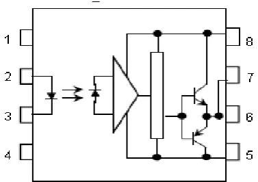
Figure 1: Pin diagram of the High side driver circuit TLP2501: N.C, 2: Anode, 3: Cathode, 4: N.C, 5: GND, 6: V0 (output), 7: V0 and 8: VCC.
As mentioned earlier, the main function of the gate driver circuit is to adapt the original low-power PWM signal to be an adequate signal that can turn on and off the IGBTs. Furthermore, by using Optocoupler as shown in the arrangement of the circuit in Figure1 the gate driver is not only capable of driving the switching devices, but also provides the electrical isolation between the control and the high power circuit. This equivalent voltage signal is reinforced by the Schmitt trigger and open collector logic gate. The Schmitt trigger is also used to provide noise rejection and improve the immunity of the circuit. The open-collector gate provides the buffer to allow enough power to turn on the Optocoupler. The HCPL-3120 Optocoupler provides isolation to separate the digital ground of the logic circuit from the floating ground reference of the high power circuit. The output voltage from the Optocoupler is directly fed to the two transistors to provide the gating voltage of +15V and -15V between the gate and the emitter of the IGBTs in order to provide turn on and turn off respectively. Special care must be taken when considering the gate resistance, Rg; its value determines the speed of the turn on and off which depends on the characteristic of the IGBT module.
5. FULL H Bridge Inverter and Driver Circuits
Figure 2: The Full H-bridge single phase inverter
IJEDR1802039
International Journal of Engineering Development and Research (
www.ijedr.org
)
224
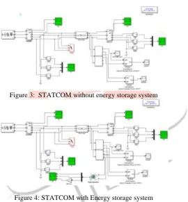
and reliability of the whole system. The idea to minimize the instability has been proposed by applying the instantaneous real power support produced by the STATCOM with energy storage to help the generator to handle the suddenly imbalanced conditions. The minimum amount of the stored energy (rating of the energy storage device) required to stabilize the system frequency has been derived.IV. SIMULATION RESULTS Modeled system
Figure 3: STATCOM without energy storage system
Figure 4: STATCOM with Energy storage system
IJEDR1802039
International Journal of Engineering Development and Research (
www.ijedr.org
)
225
'Figure5.Simulation of STATCOM without Supercapacitor
At the time when the main load is switched on, the STATCOM quickly reacts to the sudden voltage drop by supplying the reactive power current (negative Iq ) to the ac grid. According to this reactive power current, the magnitude of Vpcc increases rapidly. Consequently, as Vpcc is controlled by the STATCOM, the amount of the reactive power injection is therefore reduced proportional to the increase of the magnitude of Vpcc. During this period, due to the STATCOM supplying current to the ac grid, a small drop in the DC-link voltage is seen, as some energy in the DC-link capacitor is needed to supply losses in the system. According to the SIAICOM's DC-link voltage control reacting to this drop in order to maintain the DC-link constant, a small amount of the active power current (LI) is seen.
Figure6.Simulation of STATCOM with Supercapacitor
At time t=0s, the main load is switched on to the Vpcc bus, resulting in a sudden change of the load current. The load change causes a large voltage drop at Vpcc. At this moment, the sudden load change and the voltage drop cause the STATCOM unit to operate in full function in order to support both real and reactive power. As a result, from time t=0s onward, the STATCOM unit quickly reacts to the load change, and supplies the load demand seen as the support current trace. Initially, in order to supply the load demand, the STATCOM takes energy from the DC-link capacitor and delivers it to the ac side. During this period, the SCESS is not operating, resulting in a drop in the DC-link voltage until the SCESS starts operating at time. This DC-link voltage is controlled by the SCESS. When it reacts in this boost mode operation, the SCESS takes the stored energy in the supercapacitor modules to the DC-link capacitor, resulting in the rise in the DC-link capacitor. With the control, this rise in the DC-link voltage settles at rated value. As a consequence, an oscillation in DC-link voltage. For the whole process i.e. the boost mode, the stored energy in the supercapacitor is utilized and transferred to the ac power system, with a rate that is proportional to the demand from the ac side. The supercapacitor terminal voltage reduces according to the amount of the energy transferred. At the same time, the STATCOM control reacts quickly to the voltage drop at Vpcc and supplies reactive power to the Vpcc bus in order to maintain the magnitude of Vpcc constant. The demand of this reactive power is extracted from the error in Vpcc. Both the active and reactive power currents are controlled.
IV. CONCLUSION
IJEDR1802039
International Journal of Engineering Development and Research (
www.ijedr.org
)
226
[2] Atputharajah A, Ekanayake J, Jenkins N “Application study of a STATCOM with energy storage”, IEE Proceedings Generation Transmission and Distribution, Vol.150, No 3 May 2003 pp 368-373
[3] A. Jain, K. Joshi, A. Behal, and N. Mohan, "Voltage regulation with STATCOMs: modeling, control and results," IEEE Transactions on Power Delivery, vol. 21, no. 2, pp. 726-735, Apr 2006.
[4] H. Chong, A. Q. Huang, M. E. Baren, S. Bhattacharya, W. Litzenberger, L. Anderson, A. L. Johnson, and A. A. Edris, "STATCOM Impact Study on the Integration of a Large Wind Fann into a Weak Loop Power System," IEEE Transactions on Energy Conversion, vol. 23, no. 1, pp. 226-233, Mar 2008.