A High-Level Control Algorithm Based on sEMG
Signalling for an Elbow Joint SMA Exoskeleton
Dorin Copaci *,†,‡ ID, David Serrano‡, Luis Moreno‡and Dolores Blanco‡
Carlos III University of Madrid, Department of Systems Engineering and Automation, 28911, Leganés, Madrid, Spain; [email protected]; [email protected]; [email protected]
* Correspondence: [email protected]
† Current address: Carlos III University of Madrid, Department of Systems Engineering and Automation, 28911, Leganés, Madrid, Spain
‡ These authors contributed equally to this work.
Abstract:A high-level control algorithm capable of generating position and torque references from surface electromyography signals (sEMG) has been designed. It is applied to a shape memory alloy (SMA) actuated exoskeleton used in active rehabilitation therapies for elbow joints. The sEMG signals are filtered and normalized according data collected online during the first seconds of therapy sessions. The control algorithm uses the sEMG signals to promote active participation of patients during the therapy session. In order to generate the position reference pattern with good precision, the sEMG normalized signal is compared with a pressure sensor signal to detect the intention of each movement. The algorithm has been tested in simulations and with healthy people for control of an elbow exoskeleton in flexion–extension movements. The results indicate that sEMG signals from elbow muscles in combination with pressure sensors that measure arm–exoskeleton interaction can be used as inputs for the control algorithm, which adapts the reference for exoskeleton movements according a patient’s intention.
Keywords:exoskeleton; Electromyographic (EMG); control systems
1. Introduction
The development of advanced robotic assistive technologies has gained special attention in the scientific community over the last decades. Millions of people worldwide rely on assistive devices to improve their quality of life. For this reason, there is a need to further push the development of assistive devices by pooling the efforts of engineers and clinicians together with the feedback and experiences of users, to develop improved technologies.
Ageing of populations, mainly in developed countries, and the incidence of diseases such as stroke, spinal cord injuries, and various musculoskeletal injuries have increased the need for health resources, especially those dedicated to the rehabilitation process. Rehabilitation therapy is the process that assists a person in recovering from serious disorders after an injury, illness, or surgery that causes motor impairments. One of the most common rehabilitation methods consists of musculoskeletal rehabilitation to improve motor functions and the autonomy of patients in typical daily activities. In standard rehabilitation methods, every patient needs one or more therapists, because the therapist must directly manipulate the affected limb. This implies a huge consumption of healthcare and financial resources. The use of robotic devices as rehabilitation tools is proposed as a complement to the traditional rehabilitation sessions effectuated by therapists and can reduce the need for human resources. The main advantage offered by the use of robotic systems in rehabilitation is the capacity to support the work of physiotherapists in simple therapies with repetitive movements, reducing the need for the presence of the therapist. In this way, the costs associated with rehabilitation therapies can be reduced, allowing the same therapies to be carried out for longer, if the patient requires it, and
for a larger number of patients to be treated simultaneously. Robotic systems have proven to be as effective as conventional therapy [1,2].
Among the most promising assistive robotic technologies is exoskeletons. An exoskeleton robot is a wearable robot designed to assist the limb motions. The ease of use and the intuitive control of the robotic exoskeleton are crucial aspects for acceptance by patients. A step towards a more effective and intuitive control of upper-limb exoskeletons is the use of a myoelectric signal to detect the user’s motion intention. Myoelectric signals (MES) contain information from which data about user movement intention in terms of muscular contractions can be extracted. Control based on MES provides a more natural interaction with the exoskeleton.
A wearable shape memory alloy (SMA) exoskeleton with two degrees of freedom (DOF) (for flexion–extension and pronation–supination), actuated with SMAs was presented in [3]. In that work, the control algorithm gave the possibility to control the exoskeleton tracking a reference for passive rehabilitation therapy, in flexion [4], only actuating in flexion and recuperating (during the extension movement) with the aid of gravity, and actuating with two SMA-based actuators in flexion and extension [5]. The reference pattern in both cases represents a repetitive movement (for example a sinusoidal trajectory) defined by the therapist, which made the rehabilitation passive. In order to activate the exoskeleton according the user’s motion intention in a natural way, the control algorithm proposed in this work uses input signals to the controller based on a skin surface electromyogram (sEMG). A key aspect for the success of robotic rehabilitation therapies is to keep the patient involved in carrying out the therapy. This is the objective pursued with the proposed control algorithm. Our new control algorithm analyses the signal sEMG to detect that the patient is involved in the realization of the movement—that is, the patient intends to move their arm even if they lack sufficient muscular strength to carry out the movement. The exoskeleton will only receive a reference in position to move if the patient is generating an sEMG signal indicating their intention to move.
In order to generate the position reference pattern with good precision, the sEMG normalized signal is compared with a pressure sensor signal to detect the intention to move. The pressure sensor is used to estimate the motion of the user through the force between the user and the robot. The proposed approach has been tested in a single joint for the flexion–extension task.
1.1. Electromyogram Signals
The electromyography (EMG) signals of human muscles are biological signals that record the electrical potential generated by muscle cells to contract. It can be used to detect the user’s intention to move, since the amplitude directly correlates with the user’s muscle activity. Moreover, according to [6], the EMG signal starts about 20–80 ms before the muscle contraction, so it allows anticipation of the motion intention.
In the case of an elbow exoskeleton, it must taken into account that the human elbow motion is activated by two antagonist muscles—biceps and triceps. According to [8], the biceps brachii, brachioradialis, and brachialis muscles are involved in elbow flexion. Biceps muscles are easily accessible from the skin surface. For this reason, the sEMG electrode circuit used in this work was situated over the bicep muscles, to detect the intention of movement in the elbow joint.
1.2. Related Work
Since the 1960s, sEMG signals have been a common way of controlling prostheses [9,10]. More recently, EMG signals have been used for motion control of numerous robotic systems [11,12], prostheses [13] and robotics exoskeletons [14]. A broad review of the related literature can be found in [15].
Prosthesis and exoskeleton movements have frequently been controlled using EMG signals from muscles not involved in the movement. For example, Benjuya and Kenny [14] used the EMG signals from the wrist extensors of the forearm to open/close a pinch action. Also, in [7] the EMG signal from the ipsilateral biceps was used to develop an extremely reliable natural reaching and pinching algorithm. The EMG signals from residual biceps and triceps of a user with transhumeral amputation have been proposed to control a robotic elbow in a learning from demonstration approach [16].
In the last decades, several research groups have worked on different control algorithms based on EMG signals for use with prostheses and exoskeletons. Many of these works have focused on the use of neural networks and fuzzy algorithms to distinguish the user’s intention for movement from the EMG signals of various muscles. Hudgins [17] proved that artificial neural networks are practical for controlling prostheses by classifying different movements from EMG signals. In [18], the authors evaluate a time-delayed artificial neural network to predict shoulder and elbow motions using only EMG signals from six shoulder and elbow muscles as inputs. Results from both able-bodied subjects and subjects with tetraplegia indicate that the EMG signals contain a significant amount of information about arm movement that could be exploited in advanced control systems.
In [19] a hierarchical neuro-fuzzy controller based on the EMG signals was presented for real-time control of a shoulder and elbow motion exoskeleton. A wrist force sensor was used when the EMG activity levels were low. In [20,21] an EMG signal-based control method for a seven degrees of freedom (7DOF) upper-limb motion assistive exoskeleton robot (SUEFUL-7) is proposed. In their method, an impedance controller is applied to the muscle-model-oriented control method. Impedance parameters are adjusted in real-time as a function of the upper-limb posture and EMG activity levels. The work presented in [22] proposes a more advanced EMG-based impedance control method for an upper-limb exoskeleton. In that work, a neurofuzzy matrix modifier makes the controller adaptable to all upper-limb posture of any user. The neurofuzzy modifier is a neural network with fuzzy reasoning that is trained to adjust its output to each user before operation. The method was applied to the 7DOF exoskeleton for upper-limb joint motions, as presented in [20]. They use sixteen channels of EMG signals, with each electrode mainly corresponding to one muscle. Moreover, two force/torque sensors were used to estimate the forces between robot and user. The control algorithm is able to distinguish between different kinds of motion.
As can be seen from previously studies cited, the EMG-based fuzzy-neuro control method has proven its effectiveness to control exoskeleton robots. However, the rules of control are complicated by increasing the number of degrees of freedom of the exoskeleton.
in order to assist movement, an accurate estimate of the muscular torque may be unnecessary and a simpler control algorithm can be more efficient.
The control algorithm presented in this work is similar to the binary control algorithm used in [7,24]. In [7], DiCicco tested binary “on–off” control, variable, and natural control algorithms based on EMG signal. They validated that the EMG signal from the ipsilateral biceps could be used to develop an extremely reliable natural reaching and pinching algorithm. A specific EMG threshold value serves to determinate the output binary value: “on” if the EMG signal from the biceps muscle is above to the threshold and “off” when it is below.
In our case, the rehabilitation exoskeleton has been designed with the objective of assisting in therapies consisting of performing repetitive movements. This type of therapies are typical of the first phases of rehabilitation, where the patient must repeat define movements of a certain joint in order to recover muscular strength and increase the range of motion lost. In this context, it is not necessary to discriminate the type of movement that the patient wants to make. The proposed algorithm tries to determine the intention of the patient to initiate a certain movement and its ability to maintain it, even if they lack sufficient muscular strength to carry it out. Consequently, the sEMG signals are detected and analyzed only from muscles directly related to the movement being assisted. In this case, the biceps muscles were targeted, to detect voluntary flexion of the elbow joint.
Our proposed approach fuses sensors data with EMG signals. Force sensors were used to check the interaction between the exoskeleton and the user. In this way, only when the patient actively tries to execute the movement does the control algorithm initiate the movement of the exoskeleton. A similar approach was implemented in [20]. This approach reduces errors caused by low EMG levels or external unexpected forces affecting to the patient’s arm.
This paper presents an algorithm capable of generating the reference pattern in position and torque based on surface electromyography (sEMG) signals and pressures sensors for high-level control of the SMA exoskeleton. The first part of the paper presents an introduction to the problem. In the second section, materials and methods are explained, including the a description of the elbow exoskeleton, the firstly assembly of SMA-based actuators is presented, and the elbow exoskeleton design is shown. The electronic hardware is also presented in the second section. The final part of the second section is devoted to explaining the high-level control algorithm in detail. In third section, the results are presented, first of all the high-level control algorithm is tested in simulation; and finally, in order to evaluate the performance of the proposed control method, some experiments with healthy subjects were carried out with the SMA elbow exoskeleton. The final part presents brief conclusions of the paper.
2. Materials and Methods
This section presents a brief description of the hardware architecture on which the tests will be run: the structure of the exoskeleton, the actuators, and the sensors which are involved in the algorithm, as well as the high-level control algorithm capable of generating the reference patterns for position and torque that provide high-level control and are based on sEMG signals and pressures sensors.
2.1. Elbow SMA Exoskeleton
2.1.1. Actuator Design
The simple SMA-based actuator (with only one SMA wire) used in this work, was presented in [25]. The SMA wire is made of a metallic alloy—the most common between Nickel and Titanium, and called Nitinol [26]. It has the property of recovering its original shape (memorized shape) between two thermic transformation phases: the martensite phase (at low temperature) and an austenite phase (at high temperature). The principle on which it works is based on the heating effect (Joule effect), where electrical energy is transformed into thermal energy and after that the thermal energy is transformed into mechanical energy. During this transformation, the SMA wire undergoes a variation of total length between 3% and 5%. As a function of the diameter and alloy type, the actuator can exert different forces. A 0.51 mm diameter wire of FlexinolR [26] can exert a force of about 35.6 N (with a
lifetime of tens of millions of cycles under this force conditions). The SmartFlexR [27] wire with the
same diameter can exert a maximum force of 118 N (with a lifetime of hundreds or a few thousand cycles). The activation temperature of the SMA wire depends on the alloy and in this case it is 90◦C. In this work, the actuator was composed of multiple SMA wires, a Polytetrafluoroethylene (PTFE) tube, a Bowden tube and the terminal parts (Figure1).
Figure 1.Actuator design. Flexible shape memory alloy (SMA) based actuator.
• The Bowden cable is a mechanical flexible cable which consists of a flexible inner cable that forms a metal spiral and a flexible outer nylon sheath. This type of wire can guide the SMA actuators and transmit the force. In addition, the metal has the property of dissipating the heat, which is an advantage during the recuperation of the initial position phase.
• The PTFE tube can support high temperatures, more than 250◦C; it is an electrical insulator and does not cause friction.
• The terminal units are used at one end to connect the actuator to the actuated system and at the other to fix the SMA wires to the Bowden cable. They also serve as connectors for the power supply (using the control signal). These units are formed of two pieces that can be screwed to each other to set the tension of the SMA wires. The total SMA wire tension range adjustment is 0.01 m.
There is a relation between the SMA wire diameter, the force, and the cooling time (Table1). In Table1, the first column represents the diameter of the wire, the second column is the actuation force which guarantees a lifetime of tens millions of cycles, and the last two columns represent the cooling time for the two types of wires, with activation at 70◦C and 90◦C, respectively. According to the data shown in the table and the objectives of the exoskeleton, it was decided to work with 0.51 mm wires activated at 90◦C because the maximum force was obtained with this diameter and the cooling time is lower than when the wire activated at 70◦C.
Table 1.SMA wires characteristics [26].
Diameter Size [mm] Force [N] Cooling Time 70◦C [s] Cooling Time 90◦C [s]
0.025 0.0089 0.18 0.15
0.038 0.02 0.24 0.2
0.050 0.36 0.4 0.3
0.076 0.80 0.8 0.7
0.100 1.43 1.1 0.9
0.130 2.23 1.6 1.4
0.150 3.21 2.0 1.7
0.200 5.70 3.2 2.7
0.250 8.91 5.4 4.5
0.310 12.80 8.1 6.8
0.380 22.50 10.5 8.8
0.510 35.60 16.8 14.0
Regarding applying the necessary torque to execute defined movements (the necessary torque of each movement was found from a biomechanical simulation [3]), a summary of the system configuration of the actuators can be seen in the Table2.
Table 2.Exoskeleton actuators.
Movement SMA Wires Maximum Actuator Force [N] Length [m] Weight [kg]
Flexion 3 354 1.5 0.16
Extension 2 236 1.5 0.15
Pronation 1 118 2 0.1
Supination 1 118 2 0.1
2.1.2. Exoskeleton Design
(a) (b)
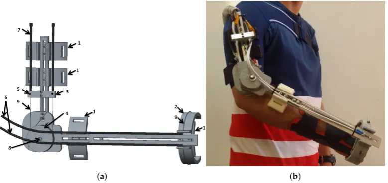
Figure 2. SMA exoskeleton design. (a) CAD structure: 1—attachment points with the hand and FSR sensors, 2—fixed structure for supination-pronation, 3—actuator termination for Bowden tube, 4—pulley for linear to rotational transformation. 5—temperature sensors 6—supination–pronation actuators 7—flexion–extension actuators 8—absolute encoder 9—SMA wires. (b) SMA elbow joint exoskeleton on a human body.
2.1.3. Electronic Hardware
The electronic hardware is composed of power electronics, a controller, and sensors placed in the device. The power electronics are capable of supplying the necessary power for four distinct actuators: flexion, extension, supination and pronation. The system is based on a MOSFET transistor (STMicroelectronics STP310N10F7, STMicroelectronics group, China), which works as a switch circuit and amplifies the control signal (PWM) generated by the controller. The device was connected to the terminal units of the SMA-based actuator.
The controller is a 32 bits microcontroller STM32F4 from STMicroelectronicsR, China, which
can be fully programmed with Matlab/SimulinkR [28]. It was programmed with four different PWM
output ports, which generate the necessary duty cycle for managing the four actuators (each one with one or more SMA wires).
The structure of the rehabilitation device includes sensors for position, temperature, force, and sEMG. An absolute angle position sensor with Hall effect (AS5045 made by AMS (Austrian Micro Systems), Premstaetten, Austria) is placed in the shaft of the exoskeleton (pulley for flexion–extension). This sensor has a resolution of 0.0879 degrees and measures the flexion–extension movement. The second position sensor, a membrane potentiometer made by Spectrasymbol with has a length of 0.1 m and is placed on the supination–pronation piece (on the outside) to measure the absolute displacement of this movement. In the same piece, in the inside part which makes the connection between the human forearm and hand, and the exoskeleton, three FSR force sensors were placed with 60 degrees angular distance bewteen each other. These sensors measured the force variation of the elbow during flexion–extension movements—forces that are involved in the high-level control algorithm. Another main sensor involved in this algorithm is the sEMG sensor. The circuit used three disposable disc electrodes, F-TC1 made by SKINTACT—a low-cost, multi-purpose ECG. It consists of Ag/AgCl electrodes, a conductive gel (Aqua-Tac), an adhesive area with a dimension of 35×41 mm and a snap connection. The gel permits a better connection between the skin and the electrode. This electrode is in the category of non-invasive and wet electrodes.
the last electrode positioned over the shoulder-blade. The EMG circuit is composed of various stages, including connectors. There is the differential active feedback stage, the digital stage (where the signal is amplified and filtered), and the stage for the power supply and communication connectors. The communication between the EMG and the microcontroller used a Serial Peripheral Interface (SPI) bus. For the signal-processing module, we used the same microcontroller STM32F4.
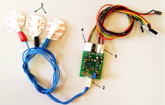
Figure 3.Surface electromyography (sEMG) circuit with two channels and the electrodes: 1—electrodes, 2—electrode connector, 3—connectors for power supply (5 V and GND ), 4—connector for Serial Peripheral Interface (SPI) communication.
The temperature sensors are placed in the terminal of the actuator to measure the temperature of the SMA wires, parameter that is required in the control loop. All the electronicS used in this project were based on low-cost components.
2.2. The High-Level Control Algorithm
Previous publications [3,5] presented a low-level control algorithm based on a BPID (Bilinear Proportional Integral Derivative) controller, which governs the SMA-based exoskeleton in position. Their algorithm, involving the position and temperature sensors, is capable to do data acquisition from the sensors or control the exoskeleton in flexion, extension, or in flexion–extension using an antagonistic controller (two BPID controllers in a parallel configuration [5]). With the data acquisition configuration, the SMA-based exoskeleton only offers the possibility to diagnostic and evaluate the patient. In the passive mode, the actuators offer all the necessary force to reach and follow the reference position without taking into account the patient force. Through the introduction of sensors for pressure/force and sEMG, the SMA-based exoskeleton offers the possibility of rehabilitation therapies in active mode, where the reference position is generated by the patient’s movement intention. In this way, passive position reference (habitually sinusoidal movements) is changed to active reference in the case where the patients present activity in the motor function (the motor function has been partially affected). Active reference involves the patient undergoing rehabilitation therapy, leading to a faster recovery. The high-level control algorithm, that generates the active rehabilitation therapy (active reference position), uses the sEMG sensors and force sensing resistor (FSR) sensors, together with position sensors. This is currently available (due to the SMA-based exoskeleton configuration—in fact, the sensors) only for the elbow flexion movement.
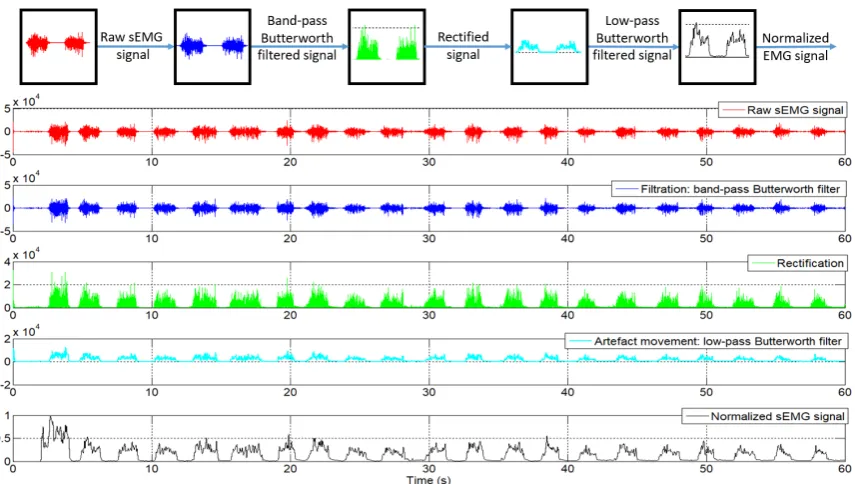
calculated, and this value was provided to second filter. This was a low-pass Butterworth filter, order 10, with a cut-off frequency of 20 Hz. The both filters were configured at a frequency of 1 kHz. After the filtering process, the EMG signal proceeds to the normalization stage. This consists of an online calibration where the first two seconds were ignored (in this first two seconds the circuit experiences some perturbation) and the next 18 s used to detect the maximum and minimum signals for the normalization process. In this time, the patient is required to flex the forearm as much as possible at least once, followed by an extension movement to return to the original position. During these 18 s, maximum and minimum values were stored to be used in the normalization process, where the normalized signal,Enorm, was calculated by the Equation (1):
Enorm= Eact−Emin
Emax−Emin
; (1)
whereEactis the actual EMG signal, andEminandEmaxare the minimum and maximum value of the EMG signal during the 18 s used for normalization.
The entire process of filtering and normalizing of the sEMG signals can be seen in Figure4.
Figure 4.sEMG signals after each processed step.
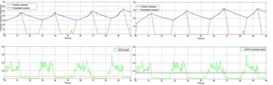
Figure 5. Left: the orange line shows data using a 0.05 threshold. Right: the black line shows data using a 0.15 threshold.
The proposed control algorithm generates the position reference as an increment of the current joint angle. That is, if movement intention is detected in the sEMG signal, the control algorithm provides a reference to increase the elbow angle of flexion. If no movement intention is detected, the position reference will be null and the actuator is disabled.
According to the actual elbow position and the final movement intention, the system works between two types of increments: one for fast position reference generation and another used to generate a slow position reference. The first increment is used when the actual position of the elbow joint is different to the position of the actuator reference. This case occurs when motion intention is detected, that is, the signal sEMG exceeds the established threshold after a period of deactivation of the actuators caused by the non-detection of intention to move. The exoskeleton used in the flexion movement leaves the joint free to move, as long as the actuator is not activated because of the loss of patient motivation and engagement that results in loss of the EMG signal. At that moment, the position reference is zero but the actual joint position is not null. This situation is shown in the descending part of the sawtooth-shaped graph in Figure5. The loss of intention of movement produces a null reference that causes deactivation of the actuator and the recovery of the intention causes a rapid increase of the position reference. If the algorithm is activated and detects an intention to move, the generated reference uses a fast increment until it reaches the elbow position, after that it uses a slow increment to generate the reference that will be followed by the exoskeleton, as long as there exists an intention of movement. When no more intention of movement is detected, the high increment is used to decrease the position reference; the actuators are no longer activated and the extension movement is carried out by actuator recuperation (dissipation of the heat).
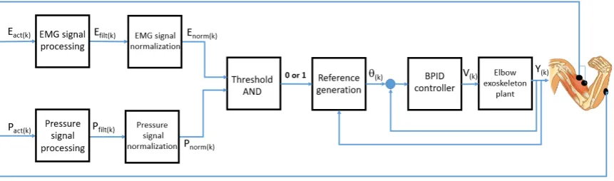
The scheme of high-level control algorithm that is capable of generating the position reference pattern can be seen in Figure6, whereEact(k)andPact(k)are the actual EMG and pressure or force signals in the discrete domain, Ef ilt(k) and Pf ilt(k)are filtered EMG and pressure or force signals,
Enorm(k)andPnorm(k)are normalized EMG and pressure or force signals,θ(k)is the generated angle
reference,V(k)is the control signal andY(k)is the angular position of the SMA-based exoskeleton.
Figure 6.High-level control algorithm based on EMG and pressure signals for position reference generation.
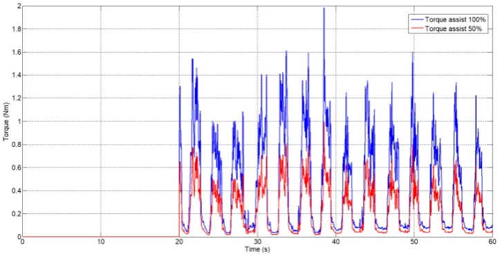
In parallel to the algorithm that generates the position reference, the normalized EMG signal is used to generate a torque assistive reference for rehabilitation therapy. According to the total height and weight of the patient, the weight of the forearm and hand was approximately calculated as well as the length from the joints to the centre of gravity of each one. As a function of these parameters and the actual angle, torque on the elbow joint has been estimated. Using this torque and the sEMG signal, a percentage of assistance in torque reference can be generated. This percentage can be set by the user. Torque assistive reference is directly proportional to the sEMG signal. A similar idea is presented in [30] but there, they do not take the biomechanical structure of the human body into account.
3. Results
In order to highlight the algorithm performance, feasibility and adaptability to various hardware configurations, a series of tests have been done. Firstly, simulation with EMG signals from different circuits together with an actuator model to simulate the behaviour of the actuator in the exoskeleton, and secondly with the real hardware over the exoskeleton with healthy subjects.
3.1. Results of Simulation
In [31], the model of the SMA-based actuator with a variable charge was presented. This permits the simulation of the actuator with different SMA diameters (0.51 mm and 0.1 mm), in this case the 0.51 mm diameter was used. According to the simulation results presented in [31], which were compared with the real behaviour of a SMA actuator, it can be concluded that the behaviour of the model has a good similarity with a real actuator. To use this model in the simulation with a high-level control algorithm based on sEMG, a number of settings of the SMA-based actuator were used. Firstly, the charge of the actuator was set according to the forearm and hand weight, and the linear position was converted to an angular position as a function of the exoskeleton characteristics, such as the pulley radius. It is worth noting that the SMA-based actuator model include the same low-level control algorithm ([3,5]) as well as the exoskeleton.
two types of sEMG circuits, firstly with the circuit realized in UC3M presented in Section2.1.3and secondly with a commercial circuit at a sampling frequency of 1 kHz.
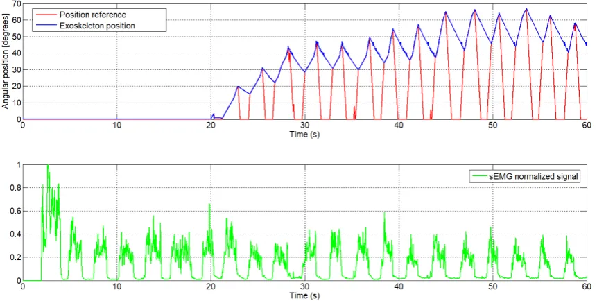
In Figure7it can be seen the normalized sEMG signal acquired from the UC3M circuit, the generated reference in function of this and the angular position of the exoskeleton. This first test was realized offline in simulation, setting the signal of FSR sensor to 1 (this means that the signal of the FSR sensor is ignored) and the increment was set empirically to 0.1 for fast increment and 0.01 for slowly increment.
Figure 7.The generated angular position reference from the sEMG signal with the UC3M circuit, first subject (male, 24 years old, 1.73 m height and 70kg weight).
As can be seen, att=20 s the position reference is 0 degrees, since this signal from the sEMG was used for calibration, whereas the first 2 s were ignored for perturbation and nextt=18 s were used to detect the maximum and minimum sEMG signal. After this process of calibration, starting at t=20 s once muscle activity has been detected in the biceps muscle, the algorithm starts to generate the reference.
We take as example the sEMG signal att=29 s (Figure8). From this moment, the normalized sEMG signal changes the amplitude, which means that the circuit detects muscular activity in the bicep muscles, and the algorithm begins to increment the position reference. Because the actual angular position of the exoskeleton is different to the actual reference, by approximately 30 degrees, the algorithm increases the angular position reference with a high increment. Once the angular position reference coincides with the exoskeleton position, the algorithm increases the angular position reference with a slow increment and the exoskeleton begins to follow the voluntary movement intention. In t=32.5 s, the amplitude of the normalized sEMG signal decreases, the high-level control algorithm interprets that there is no intention to move by the user and, therefore, the algorithm decreases the angular position reference. In this case, though the reference decreases very fast, the angular position of the actuator is limited by the actuator behaviour (shows a slow recovery due to heat accumulation). The sEMG threshold can easily be set from the user interface and in this case was set to 0.05.
going to 0 degrees. The exoskeleton behaviour can be seen when the extension actuator is not active: it represents a slow extension movement.
Figure 8.The angular position reference generated by the sEMG signal, first subject (enlarged area).
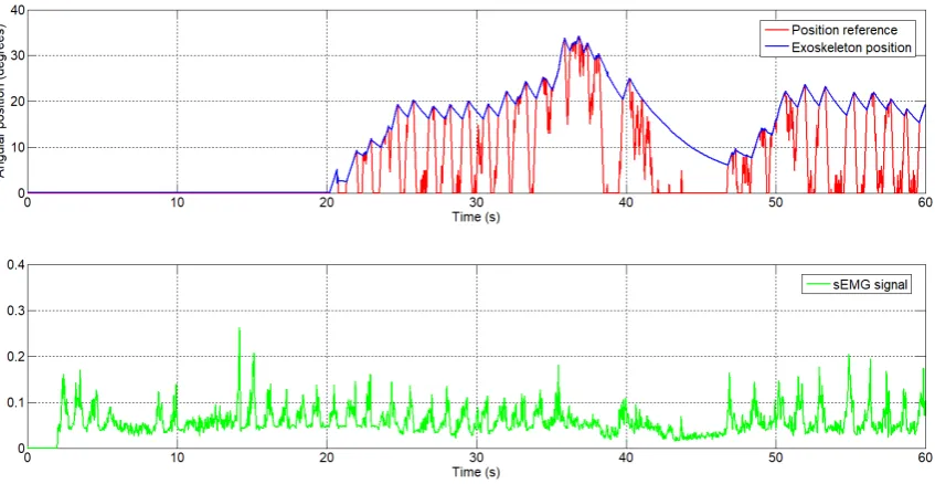
Figure 9.The generated angular position reference by the sEMG signal, second subject.
Figure 10.The generated torque reference from the sEmg signal.
3.2. Results with the Real SMA Exoskeleton
The sEMG based control algorithm was tested in the real exoskeleton presented in Section2. This was tested with healthy people from RoboticsLab laboratory, Carlos III University of Madrid. The characteristics of the subject were: male, 1.73 m height and 70 kg weight. Firstly, sEMG electrodes were fixed over the biceps (over the belly of the biceps, a good positioning is essential) and the shoulder (reference electrode), and then the exoskeleton was fitted over the body. The exoskeleton was configured on the subject’s body so that the elbow axis was aligned with the exoskeleton rotation axis and the FSR sensors were in contact with the hand and forearm. The results of this test can be seen in Figure11, showing the reference position signal (the blue signal) generated by the sEMG signal (purple) and the FSR signal (green), and the real position exoskeleton (red).
According to the high-level control algorithm, in the first 20 s, the exoskeleton user calibrates the algorithm through movements of flexion–extension of the elbow joint. In Figure11, two movements of flexion–extension can be observed during the first 20 s. In these first seconds the output reference is 0 degrees. In the second graphic, the sEMG signals can be seen, where the amplitude is changing during the flexion–extension movement. In the third graphic is the FSR sensor signal variation corresponding to the flexion–extension movement. After the process of calibration, when the algorithm detects the movement intention (from the sEMG signal and FSR sensor), it starts to generate the reference position and the exoskeleton begins to move following the reference. We take as a reference example the intervalt= 23 to 40 s. Att = 23 s, the FSR sensor presents a signal with a high amplitude which exceeds the value of the threshold, and the sEMG signal also begins to increase in amplitude. Starting from this point, the algorithm begins to generate the angular reference incrementing slowly, as the angular reference is near to the exoskeleton elbow position. Untilt=30 s, the amplitude of the sEMG signal remains high, with the angular reference reaching the maximum 120 degrees. Due to the elbow movement, the FSR sensor signal amplitude may have reduced and for this reason the weight of this signal (during this period) on the algorithm is lower. After timet=30 tot=40 s, the sEMG signal has decreased its amplitude and the algorithm starts to decrease the angular reference, finally to 0 degrees.
0 10 20 30 40 50 60 70 80 90 100 0 50 100 Time (s) A n gu la r p os iti on ( de g re e s) Exoskeleton position Position reference
0 10 20 30 40 50 60 70 80 90 100
0 0.5 1
Time (s)
sEMG normalized signal
0 10 20 30 40 50 60 70 80 90 100
0.7 0.8 0.9 1
Time (s)
FSR normalized signal
Figure 11.Position reference and response generated by the sEMG signal.
4. Conclusions
In this work a new high-level control algorithm based on sEMG signals and pressure/force signals capable of generating the angular and torque reference for an active rehabilitation was presented. An algorithm capable of generating the angular and torque reference was successfully tested in simulations (with the EMG signals provided by the circuit made by the research group and a commercial circuit) and in real applications over the SMA elbow exoskeleton with healthy people. In the later case, in a real device, the sEMG signal was used together with the force/pressure signals for a FSR sensor.
The SMA-based exoskeleton for an elbow joint presented in this work, together with the low and high-level control algorithm and sensors, is based on low-cost components and offers three modes of operation:
• Data acquisition mode: to evaluate and diagnose the patient. Also, in this mode of operation the angular limits of elbow movement are saved to set the angular reference limits for the control algorithm.
• Passive rehabilitation mode: The exoskeleton follows a defined angular reference, the most common being a sinusoidal type. In this case, the patient executes repetitive movements, not taking into account the movement intention of the patient. The exoskeleton can support all the movement in flexion, extension or flexion–extension.
The main advantage provided by the proposed high-level controller is that it forces the patient to be involved in the therapy task on a constant basis. If the patient loses attention, the exoskeleton is deactivated. In this way, the controller promotes the active rehabilitation.
Author Contributions: L.M. was in charge of project administration and funding acquisition. D.C. and L.M. designed the exoskeleton. D.C. developed the control method and carried out the experiments. D.S. collaborated in experiments. D.B. supervised the research. D.C. and D.B. wrote the manuscript.
Funding:The research was funded by RoboHealth (DPI2013-47944-C4-3-R) and the EDAM (DPI2016-75346-R) Spanish research projects.
Acknowledgments:The authors are grateful for the collaboration of the LAMBECOM research group, of Rey Juan Carlos University of Madrid, Spain, in defining the design requirements of the rehabilitation device and their participation in the evaluation of preliminary designs.
Conflicts of Interest:The authors declare no conflict of interest.
Abbreviations
The following abbreviations are used in this manuscript:
SMA Shape Memory Alloy
UC3M Carlos III University of Madrid FSR Force Sensing Resistor
PWM Pulse-Width Modulation) sEMG Surface electromyography PTFE Polytetrafluoroethylene DOF Degrees of freedom SPI Serial Peripheral Interface MES Myoelectric signals
References
1. Harwin, W.S.; Murgia, A.; Stokes, E.K. Assessing the effectiveness of robot facilitates neurorehabilitation for relearning motor skills.Med. Biol. Eng. Comput.2011,49, 1093–1102.
2. Pons, J.L. (Ed.)Wearable Robots; John Wiley & Sons, Ltd.: Chichester, UK, 2008.
3. Copaci, D.; Flores, A.; Rueda, F.; Alguacil, I.; Blanco, D.; Moreno, L. Wearable Elbow Exoskeleton Actuated with Shape Memory Alloy. InConverging Clinical and Engineering Research on Neurorehabilitation II, Proceedings of the 3rd International Conference on NeuroRehabilitation (ICNR2016), Segovia, Spain, 18–21 October 2016; Springer, Cham, pp. 477–481.
4. Copaci, D. Non-Linear Actuators and Simulation Tools for Rehabilitation Devices. Ph.D. Thesis, Carlos III University, Getafe, Spain, 2017.
5. Copaci, D.; Blanco, D.; Moreno, L. Wearable elbow exoskeleton actuated with Shape Memory Alloy in antagonist movement. In Proceedings of the Joint Workshop on Wearable Robotics and Assistive Devices, International Conference on Intelligent Robots and Systems (IROS 2016), Daejeon, Korea, 9–14 October 2016. 6. Norman, R.W.; Komi, P.V. Electromechanical delay in skeletal muscle under normal movement conditions.
Acta Physiol. Scand.1979,106, 241–248.
7. DiCicco, M.; Lucas, L.; Matsuoka, Y. Comparison of Two Control Strategies for a Muscle Controlled Orthotic Exoskeleton for the Hand. In Proceedings of the IEEE International Conference on Robotics and Automation, New Orleans, LA, USA, 26 April–1 May 2004; pp. 1622–1627.
8. Martini, F.H.; Timmons, M.J.; Tallitsch, R.B.Human Anatomy; Pearson Education Inc.: Old Tappan, NJ, USA, 1997; ISBN 0-13-049178-0.
9. Battye, C.K.; Nightingale, A.; Whillis, J. The use of myo-electric currents in the operation of prostheses. J. Bone Jt. Surg.1955,37, 506–510.
10. Bottomley, A.H. Myo-electric control of powered prostheses.J. Bone Jt. Surg.1965,47, 411–415.
12. Fukuda, O.; Tsuji, T.; Ohtsuka, A.; Kaneko, M. EMG-based Human-Robot Interface for Rehabilitation Aid. In Proceedings of the IEEE International Conference on Robotics and Automation, Leuven, Belgium, 16–20 May 1998; pp. 3942–3947.
13. Kuribayashi, K.; Shimizu, S.; Okimura, K.; Taniguchi, T. A discrimination system using neural netwok for EMG-control prostheses-Integral type of emg signal processing. In Proceedings of the 1993 IEEERSJ International Conference on Intelligent Robots and Systems, Yokohama, Japan, 26–30 July 1993; pp. 1750–1755.
14. Benjnya, N.; Kenney, S.B. Myoelectric Hand Orthosis.J. Prosthet. Orthot.1990,2, 149–154.
15. Singh, R.M.; Chatterji, S. Trends and Callenges in EMG Based Control Scheme of Exoskeleton Robots—A Review.Int. J. Sci. Eng. Res.2012,3, 506–510.
16. Vasan, G.; Pilarski, P. Learning from Demonstration: Teaching a Myoelectric Prosthesis with an Intact Limb via Reinforcement Learning. In Proceedings of the 15th International Conference on Rehabilitation Robotics (ICORR2017), London, UK, 17–20 July 2017.
17. Hudgins, B.; Parker, P.; Scott, R. A new strategy for multifunction myoelectric control. IEEE Trans. Biomed. Eng.1993,40, 82–94.
18. Au, A.T.C.; Kirsch, R.F. EMG-based prediction of shoulder and elbow kinematics in able-bodied and spinal cord injured individuals.IEEE Trans. Rehabil. Eng.2000,8, 471–480.
19. Kiguchi, K.; Tanaka, T.; Fukuda, T. Neuro-Fuzzy Control of a Robotic Exoskeleton with EMG Signals. IEEE Trans. Fuzzy Syst.2004,12, 481–490.
20. Gopura, R.; Kiguchi, K. An Exoskeleton Robot for Human Forearm and Wrist Motion Assist- Hardware Design and EMG-Based Controller.Int. J. Adv. Mech. Des. Syst. Manuf.2008,2, 1067–1083.
21. Gopura, R.; Kiguchi, K. Application of Surface Electromyographic Signals to Control Exoskeleton Robots. InApplications of EMG in Clinical and Sports Medicine Catriona Steele; IntechOpen, Rijeka, Croatia, 2012. 22. Kiguchi, K.; Hayashi, Y. An EMG-Based Control for an Upper-Limb Power-Assist Exoskeleton Robot.
IEEE Trans. Syst. Man Cybern. Part B (Cybern.)2012,42, 1064–1071.
23. Lenzi, T.; de Rossi, S.M.M.; Vitiello, N.; Carroza, M.C. Intention-Based EMG Control of Powered Exoskeletons. IEEE Trans. Biomed. Eng.2012,58, 2180–2190.
24. Lucas, L.; DiCicco, M.; Matsuoka, Y. An EMG-Controlled Hand Exoskeleton for Natural Pinching.J. Robot. Mechatron.2004,16, 482–488.
25. Villoslada, A.; Flores, A.; Copaci, D.; Blanco, D.; Moreno, L. High displacement flexible shape memory alloy actuator for soft wearable robots.Robot. Auton. Syst.2015,73, 91–101.
26. Technical Characteristics of Flexinol, Dynalloy, Inc. Makers of Dynamic Alloys. Available online: http://www.dynalloy.com/(accessed on 18/06/2018).
27. Saes Group. Available online:https://www.saesgetters.com/(accessed on 18/06/2018).
28. Flores, A.; Copaci, D.; Villoslada, A.; Blanco, D.; Moreno, L. Sistema Avanzado de Protipado Rápido para Control en la Educación en Ingeniería para grupos Multidisciplinares.Revista Iberoamericana de Automática e Informática Industrial RIAI2016,13, 350–362.
29. De Luca, C.J.; Gilmore, L.D.; Kuznetsov, M.; Roy, S.H. Filtering the surface EMG signal: Movement artifact and baseline noise contamination.J. Biomech.2010,43, 1573–1579. doi:10.1016/j.jbiomech.2010.01.027. 30. Song, R.; Tong, K.-Y.; Hu, X.; Li, L. Assistive Control System Using Continuous Myoelectric Signal in
Robot-Aided Arm Training for Patients after Stroke.IEEE Trans. Neural Syst. Rehabil. Eng.2008,16, 371–379. 31. Copaci, D.; Flores, A.; Villoslada, A.; Blanco, D. Modelado y Simulación de Actuadores SMA con Carga

![Table 1. SMA wires characteristics [26].](https://thumb-us.123doks.com/thumbv2/123dok_us/1078717.1608610/6.595.114.481.357.421/table-sma-wires-characteristics.webp)